EP1634548A2 - Modular system for replacement of radial head - Google Patents
Modular system for replacement of radial head Download PDFInfo
- Publication number
- EP1634548A2 EP1634548A2 EP05019493A EP05019493A EP1634548A2 EP 1634548 A2 EP1634548 A2 EP 1634548A2 EP 05019493 A EP05019493 A EP 05019493A EP 05019493 A EP05019493 A EP 05019493A EP 1634548 A2 EP1634548 A2 EP 1634548A2
- Authority
- EP
- European Patent Office
- Prior art keywords
- implant
- endoprosthetic
- cannulated body
- joint implant
- end cap
- Prior art date
- Legal status (The legal status is an assumption and is not a legal conclusion. Google has not performed a legal analysis and makes no representation as to the accuracy of the status listed.)
- Granted
Links
- 239000007943 implant Substances 0.000 claims abstract description 42
- 210000000988 bone and bone Anatomy 0.000 claims abstract description 10
- 230000000295 complement effect Effects 0.000 claims description 8
- 239000000017 hydrogel Substances 0.000 claims description 6
- 239000000919 ceramic Substances 0.000 claims description 3
- 239000002184 metal Substances 0.000 claims description 2
- 229910052751 metal Inorganic materials 0.000 claims description 2
- 239000004033 plastic Substances 0.000 claims description 2
- 229920003023 plastic Polymers 0.000 claims description 2
- 230000003993 interaction Effects 0.000 claims 1
- 239000000463 material Substances 0.000 abstract description 8
- 229910001069 Ti alloy Inorganic materials 0.000 description 3
- 210000003484 anatomy Anatomy 0.000 description 3
- 239000007769 metal material Substances 0.000 description 3
- 230000008439 repair process Effects 0.000 description 3
- 238000011282 treatment Methods 0.000 description 3
- 238000004873 anchoring Methods 0.000 description 2
- 239000011324 bead Substances 0.000 description 2
- 239000011248 coating agent Substances 0.000 description 2
- 238000000576 coating method Methods 0.000 description 2
- 230000009977 dual effect Effects 0.000 description 2
- 230000008407 joint function Effects 0.000 description 2
- 238000000034 method Methods 0.000 description 2
- 238000012986 modification Methods 0.000 description 2
- 230000004048 modification Effects 0.000 description 2
- 229920000642 polymer Polymers 0.000 description 2
- 239000004926 polymethyl methacrylate Substances 0.000 description 2
- 238000001356 surgical procedure Methods 0.000 description 2
- 210000001519 tissue Anatomy 0.000 description 2
- XLYOFNOQVPJJNP-UHFFFAOYSA-N water Substances O XLYOFNOQVPJJNP-UHFFFAOYSA-N 0.000 description 2
- 241001567848 Capitellum Species 0.000 description 1
- 229910000684 Cobalt-chrome Inorganic materials 0.000 description 1
- 241000282412 Homo Species 0.000 description 1
- 229920005479 Lucite® Polymers 0.000 description 1
- 239000004677 Nylon Substances 0.000 description 1
- 229920005372 Plexiglas® Polymers 0.000 description 1
- 239000004696 Poly ether ether ketone Substances 0.000 description 1
- 239000004952 Polyamide Substances 0.000 description 1
- RTAQQCXQSZGOHL-UHFFFAOYSA-N Titanium Chemical compound [Ti] RTAQQCXQSZGOHL-UHFFFAOYSA-N 0.000 description 1
- 208000027418 Wounds and injury Diseases 0.000 description 1
- JUPQTSLXMOCDHR-UHFFFAOYSA-N benzene-1,4-diol;bis(4-fluorophenyl)methanone Chemical compound OC1=CC=C(O)C=C1.C1=CC(F)=CC=C1C(=O)C1=CC=C(F)C=C1 JUPQTSLXMOCDHR-UHFFFAOYSA-N 0.000 description 1
- 239000000560 biocompatible material Substances 0.000 description 1
- 239000012620 biological material Substances 0.000 description 1
- 238000005422 blasting Methods 0.000 description 1
- 239000010952 cobalt-chrome Substances 0.000 description 1
- 230000001010 compromised effect Effects 0.000 description 1
- 230000006378 damage Effects 0.000 description 1
- 201000010099 disease Diseases 0.000 description 1
- 208000037265 diseases, disorders, signs and symptoms Diseases 0.000 description 1
- 239000002612 dispersion medium Substances 0.000 description 1
- 239000000499 gel Substances 0.000 description 1
- 210000002758 humerus Anatomy 0.000 description 1
- 229910052588 hydroxylapatite Inorganic materials 0.000 description 1
- 238000011065 in-situ storage Methods 0.000 description 1
- 208000014674 injury Diseases 0.000 description 1
- 238000003780 insertion Methods 0.000 description 1
- 230000037431 insertion Effects 0.000 description 1
- 229920001778 nylon Polymers 0.000 description 1
- 229920000620 organic polymer Polymers 0.000 description 1
- XYJRXVWERLGGKC-UHFFFAOYSA-D pentacalcium;hydroxide;triphosphate Chemical compound [OH-].[Ca+2].[Ca+2].[Ca+2].[Ca+2].[Ca+2].[O-]P([O-])([O-])=O.[O-]P([O-])([O-])=O.[O-]P([O-])([O-])=O XYJRXVWERLGGKC-UHFFFAOYSA-D 0.000 description 1
- 230000000704 physical effect Effects 0.000 description 1
- 229920002647 polyamide Polymers 0.000 description 1
- 229920000728 polyester Polymers 0.000 description 1
- 229920002530 polyetherether ketone Polymers 0.000 description 1
- 238000002360 preparation method Methods 0.000 description 1
- 238000002271 resection Methods 0.000 description 1
- 239000010936 titanium Substances 0.000 description 1
- 229910052719 titanium Inorganic materials 0.000 description 1
Images


Classifications
-
- A—HUMAN NECESSITIES
- A61—MEDICAL OR VETERINARY SCIENCE; HYGIENE
- A61F—FILTERS IMPLANTABLE INTO BLOOD VESSELS; PROSTHESES; DEVICES PROVIDING PATENCY TO, OR PREVENTING COLLAPSING OF, TUBULAR STRUCTURES OF THE BODY, e.g. STENTS; ORTHOPAEDIC, NURSING OR CONTRACEPTIVE DEVICES; FOMENTATION; TREATMENT OR PROTECTION OF EYES OR EARS; BANDAGES, DRESSINGS OR ABSORBENT PADS; FIRST-AID KITS
- A61F2/00—Filters implantable into blood vessels; Prostheses, i.e. artificial substitutes or replacements for parts of the body; Appliances for connecting them with the body; Devices providing patency to, or preventing collapsing of, tubular structures of the body, e.g. stents
- A61F2/02—Prostheses implantable into the body
- A61F2/30—Joints
- A61F2/38—Joints for elbows or knees
- A61F2/3804—Joints for elbows or knees for elbows
-
- A—HUMAN NECESSITIES
- A61—MEDICAL OR VETERINARY SCIENCE; HYGIENE
- A61F—FILTERS IMPLANTABLE INTO BLOOD VESSELS; PROSTHESES; DEVICES PROVIDING PATENCY TO, OR PREVENTING COLLAPSING OF, TUBULAR STRUCTURES OF THE BODY, e.g. STENTS; ORTHOPAEDIC, NURSING OR CONTRACEPTIVE DEVICES; FOMENTATION; TREATMENT OR PROTECTION OF EYES OR EARS; BANDAGES, DRESSINGS OR ABSORBENT PADS; FIRST-AID KITS
- A61F2/00—Filters implantable into blood vessels; Prostheses, i.e. artificial substitutes or replacements for parts of the body; Appliances for connecting them with the body; Devices providing patency to, or preventing collapsing of, tubular structures of the body, e.g. stents
- A61F2/02—Prostheses implantable into the body
- A61F2/30—Joints
- A61F2/30767—Special external or bone-contacting surface, e.g. coating for improving bone ingrowth
-
- A—HUMAN NECESSITIES
- A61—MEDICAL OR VETERINARY SCIENCE; HYGIENE
- A61F—FILTERS IMPLANTABLE INTO BLOOD VESSELS; PROSTHESES; DEVICES PROVIDING PATENCY TO, OR PREVENTING COLLAPSING OF, TUBULAR STRUCTURES OF THE BODY, e.g. STENTS; ORTHOPAEDIC, NURSING OR CONTRACEPTIVE DEVICES; FOMENTATION; TREATMENT OR PROTECTION OF EYES OR EARS; BANDAGES, DRESSINGS OR ABSORBENT PADS; FIRST-AID KITS
- A61F2/00—Filters implantable into blood vessels; Prostheses, i.e. artificial substitutes or replacements for parts of the body; Appliances for connecting them with the body; Devices providing patency to, or preventing collapsing of, tubular structures of the body, e.g. stents
- A61F2/02—Prostheses implantable into the body
- A61F2/30—Joints
- A61F2/42—Joints for wrists or ankles; for hands, e.g. fingers; for feet, e.g. toes
-
- A—HUMAN NECESSITIES
- A61—MEDICAL OR VETERINARY SCIENCE; HYGIENE
- A61F—FILTERS IMPLANTABLE INTO BLOOD VESSELS; PROSTHESES; DEVICES PROVIDING PATENCY TO, OR PREVENTING COLLAPSING OF, TUBULAR STRUCTURES OF THE BODY, e.g. STENTS; ORTHOPAEDIC, NURSING OR CONTRACEPTIVE DEVICES; FOMENTATION; TREATMENT OR PROTECTION OF EYES OR EARS; BANDAGES, DRESSINGS OR ABSORBENT PADS; FIRST-AID KITS
- A61F2/00—Filters implantable into blood vessels; Prostheses, i.e. artificial substitutes or replacements for parts of the body; Appliances for connecting them with the body; Devices providing patency to, or preventing collapsing of, tubular structures of the body, e.g. stents
- A61F2/02—Prostheses implantable into the body
- A61F2/30—Joints
- A61F2002/30001—Additional features of subject-matter classified in A61F2/28, A61F2/30 and subgroups thereof
- A61F2002/30316—The prosthesis having different structural features at different locations within the same prosthesis; Connections between prosthetic parts; Special structural features of bone or joint prostheses not otherwise provided for
- A61F2002/30535—Special structural features of bone or joint prostheses not otherwise provided for
- A61F2002/30604—Special structural features of bone or joint prostheses not otherwise provided for modular
-
- A—HUMAN NECESSITIES
- A61—MEDICAL OR VETERINARY SCIENCE; HYGIENE
- A61F—FILTERS IMPLANTABLE INTO BLOOD VESSELS; PROSTHESES; DEVICES PROVIDING PATENCY TO, OR PREVENTING COLLAPSING OF, TUBULAR STRUCTURES OF THE BODY, e.g. STENTS; ORTHOPAEDIC, NURSING OR CONTRACEPTIVE DEVICES; FOMENTATION; TREATMENT OR PROTECTION OF EYES OR EARS; BANDAGES, DRESSINGS OR ABSORBENT PADS; FIRST-AID KITS
- A61F2/00—Filters implantable into blood vessels; Prostheses, i.e. artificial substitutes or replacements for parts of the body; Appliances for connecting them with the body; Devices providing patency to, or preventing collapsing of, tubular structures of the body, e.g. stents
- A61F2/02—Prostheses implantable into the body
- A61F2/30—Joints
- A61F2/30767—Special external or bone-contacting surface, e.g. coating for improving bone ingrowth
- A61F2002/30769—Special external or bone-contacting surface, e.g. coating for improving bone ingrowth madreporic
-
- A—HUMAN NECESSITIES
- A61—MEDICAL OR VETERINARY SCIENCE; HYGIENE
- A61F—FILTERS IMPLANTABLE INTO BLOOD VESSELS; PROSTHESES; DEVICES PROVIDING PATENCY TO, OR PREVENTING COLLAPSING OF, TUBULAR STRUCTURES OF THE BODY, e.g. STENTS; ORTHOPAEDIC, NURSING OR CONTRACEPTIVE DEVICES; FOMENTATION; TREATMENT OR PROTECTION OF EYES OR EARS; BANDAGES, DRESSINGS OR ABSORBENT PADS; FIRST-AID KITS
- A61F2/00—Filters implantable into blood vessels; Prostheses, i.e. artificial substitutes or replacements for parts of the body; Appliances for connecting them with the body; Devices providing patency to, or preventing collapsing of, tubular structures of the body, e.g. stents
- A61F2/02—Prostheses implantable into the body
- A61F2/30—Joints
- A61F2/30767—Special external or bone-contacting surface, e.g. coating for improving bone ingrowth
- A61F2002/30906—Special external or bone-contacting surface, e.g. coating for improving bone ingrowth shot- sand- or grit-blasted
-
- A—HUMAN NECESSITIES
- A61—MEDICAL OR VETERINARY SCIENCE; HYGIENE
- A61F—FILTERS IMPLANTABLE INTO BLOOD VESSELS; PROSTHESES; DEVICES PROVIDING PATENCY TO, OR PREVENTING COLLAPSING OF, TUBULAR STRUCTURES OF THE BODY, e.g. STENTS; ORTHOPAEDIC, NURSING OR CONTRACEPTIVE DEVICES; FOMENTATION; TREATMENT OR PROTECTION OF EYES OR EARS; BANDAGES, DRESSINGS OR ABSORBENT PADS; FIRST-AID KITS
- A61F2/00—Filters implantable into blood vessels; Prostheses, i.e. artificial substitutes or replacements for parts of the body; Appliances for connecting them with the body; Devices providing patency to, or preventing collapsing of, tubular structures of the body, e.g. stents
- A61F2/02—Prostheses implantable into the body
- A61F2/30—Joints
- A61F2/30767—Special external or bone-contacting surface, e.g. coating for improving bone ingrowth
- A61F2002/30934—Special articulating surfaces
- A61F2002/30935—Concave articulating surface composed of a central conforming area surrounded by a peripheral annular non-conforming area
-
- A—HUMAN NECESSITIES
- A61—MEDICAL OR VETERINARY SCIENCE; HYGIENE
- A61F—FILTERS IMPLANTABLE INTO BLOOD VESSELS; PROSTHESES; DEVICES PROVIDING PATENCY TO, OR PREVENTING COLLAPSING OF, TUBULAR STRUCTURES OF THE BODY, e.g. STENTS; ORTHOPAEDIC, NURSING OR CONTRACEPTIVE DEVICES; FOMENTATION; TREATMENT OR PROTECTION OF EYES OR EARS; BANDAGES, DRESSINGS OR ABSORBENT PADS; FIRST-AID KITS
- A61F2250/00—Special features of prostheses classified in groups A61F2/00 - A61F2/26 or A61F2/82 or A61F9/00 or A61F11/00 or subgroups thereof
- A61F2250/0058—Additional features; Implant or prostheses properties not otherwise provided for
- A61F2250/006—Additional features; Implant or prostheses properties not otherwise provided for modular
-
- A—HUMAN NECESSITIES
- A61—MEDICAL OR VETERINARY SCIENCE; HYGIENE
- A61F—FILTERS IMPLANTABLE INTO BLOOD VESSELS; PROSTHESES; DEVICES PROVIDING PATENCY TO, OR PREVENTING COLLAPSING OF, TUBULAR STRUCTURES OF THE BODY, e.g. STENTS; ORTHOPAEDIC, NURSING OR CONTRACEPTIVE DEVICES; FOMENTATION; TREATMENT OR PROTECTION OF EYES OR EARS; BANDAGES, DRESSINGS OR ABSORBENT PADS; FIRST-AID KITS
- A61F2310/00—Prostheses classified in A61F2/28 or A61F2/30 - A61F2/44 being constructed from or coated with a particular material
- A61F2310/00005—The prosthesis being constructed from a particular material
- A61F2310/00011—Metals or alloys
- A61F2310/00023—Titanium or titanium-based alloys, e.g. Ti-Ni alloys
-
- A—HUMAN NECESSITIES
- A61—MEDICAL OR VETERINARY SCIENCE; HYGIENE
- A61F—FILTERS IMPLANTABLE INTO BLOOD VESSELS; PROSTHESES; DEVICES PROVIDING PATENCY TO, OR PREVENTING COLLAPSING OF, TUBULAR STRUCTURES OF THE BODY, e.g. STENTS; ORTHOPAEDIC, NURSING OR CONTRACEPTIVE DEVICES; FOMENTATION; TREATMENT OR PROTECTION OF EYES OR EARS; BANDAGES, DRESSINGS OR ABSORBENT PADS; FIRST-AID KITS
- A61F2310/00—Prostheses classified in A61F2/28 or A61F2/30 - A61F2/44 being constructed from or coated with a particular material
- A61F2310/00005—The prosthesis being constructed from a particular material
- A61F2310/00179—Ceramics or ceramic-like structures
-
- A—HUMAN NECESSITIES
- A61—MEDICAL OR VETERINARY SCIENCE; HYGIENE
- A61F—FILTERS IMPLANTABLE INTO BLOOD VESSELS; PROSTHESES; DEVICES PROVIDING PATENCY TO, OR PREVENTING COLLAPSING OF, TUBULAR STRUCTURES OF THE BODY, e.g. STENTS; ORTHOPAEDIC, NURSING OR CONTRACEPTIVE DEVICES; FOMENTATION; TREATMENT OR PROTECTION OF EYES OR EARS; BANDAGES, DRESSINGS OR ABSORBENT PADS; FIRST-AID KITS
- A61F2310/00—Prostheses classified in A61F2/28 or A61F2/30 - A61F2/44 being constructed from or coated with a particular material
- A61F2310/00389—The prosthesis being coated or covered with a particular material
- A61F2310/00592—Coating or prosthesis-covering structure made of ceramics or of ceramic-like compounds
- A61F2310/00796—Coating or prosthesis-covering structure made of a phosphorus-containing compound, e.g. hydroxy(l)apatite
Definitions
- the present invention relates to endoprosthetic articular joint implants, and more specifically to methods and apparatus for replacing a radial head using a modular implant.
- Joint function can be lost due to fracture or damaged joint surfaces, for example. Joints compromised in these ways typically have suffered injury or disease. Repair often entails endoprosthetic implants installed in place of resected bone-ends to replace the damaged joint and restore joint function.
- a radial head implant system is disclosed in U.S. Pat. No. 6,361,563 to Terrill-Grisoni et al.
- the modular system includes a head and a stem.
- a complex system is used to adapt the radius of the head.
- Joint-replacements are known that generally include an intramedullary stem anchoring a curved joint surface.
- U.S. Pat. No. 5,061,288 to Berggren et al. Berggren et al. discloses a joint implant that features a surface-replacing portion attached to the end of an axial support. Bristles extend radially from the axial support sufficient to be urged proximally upon insertion to the canal. The bristles consequently are biased against removal of the implant, thereby acting as barbs to anchor the surface-replacing portion of the implant on the end of resected bone.
- a joint-surface material features a dove-tail groove that engages a base with a corresponding pin attached to the axial support.
- French patent document no. 2,605,878 in the name of Condamine discloses a two part joint prosthesis. Referring to FIGS. 1-3 of Condamine, the implant features an articulating surface portion that is adhered to a ribbed intramedullary stem.
- Another French patent document, no. 1,122,634 in the name of van Steenbrugghe discloses implants with coated spherical ends.
- the coating can include a polymer, such as Plexiglas, Lucite, polyamides (e.g., nylon), polyesters, and fluorethylenes, for example.
- U.S. Patent No. 5,314,486 to Zang et al. discloses a phalangeal implant having an insertable bearing-surface.
- the implant lacks an ability to adjust alignment between respective joint components.
- the invention provides a modular endoprosthetic radial head replacement implant.
- the implant features an end cap that fits into a cannulated body connected to an anchoring screw.
- the screw has a spherical head and fits into the cannulated body to engage complementary internal geometry of the cannulated body.
- the end cap is manufactured from a material that provides an appropriate bearing surface.
- the invention is described herein mostly in connection with replacing the proximal end of a radius for articulating with the capitellum of a humerus.
- Other configurations are possible, however.
- the radial depression of the bearing surface can be radiused according to the type of joint being replaced, i.e., the depression can feature a single radius, a dual radius, an eccentric radius, etc.
- the bases of the end cap and the base can be configured with a slant, for example, to sit flush with a variety of bone surfaces.
- an appropriated combination of modular components is selected to match a patient's anatomy.
- the fractured radius is resected using instrumentation configured to accommodate the implant.
- the threaded end of the screw is passed into the body to nest with the internal geometry of the body.
- the screw, engaged with a driver is advanced with turning into the intermedullary canal of the radius.
- a spanner-type wrench may be used to rotate the body to improve fit or alignment.
- a jam nut is advanced along threads formed within the body and tightened onto the screw head. Once the screw is locked in place to maintain alignment with respect to the body, the end cap is assembled onto the body to complete the construct.
- FIG. 1 is a perspective illustration of a modular radial head prosthesis with a single-radius end cap surface according to the present invention
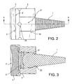
- FIG. 2 is a plan view of the modular implant of FIG. 1, with alternative configurations shown by broken lines;
- FIG. 3 is a cross-sectional view taken along the line A-A in FIG. 2;
- FIG. 4 is a view of the modular implant taken from the distal end of the screw to show the bone-engaging surface of the implant body;
- FIG. 5 is a view of the end cap proximal surface showing an alternative eccentric radius surface depression
- FIG. 6 is an enlarged view of the end cap proximal surface showing an alternative dual-radius surface depression
- FIG. 7 is a side view of an alternative ceramic end cap formed with a Morse taper.
- Implant 1 includes three component modules: an end cap 3, a body 5, and a screw 7.
- the components can be offered in a variety of interchangeable sizes and configurations, exemplary examples of which are described in further detail below.
- End cap 3 may be manufactured from hydrogel, polished titanium, polished CoCr, PEEK, plastics, polymers, and other biocompatible materials. Metal surfaces may be coated or treated to enhance bearing properties.
- Hydrogels are colloidal gels in which water is the dispersion medium.
- An exemplary hydrogel material contains water in similar proportions to human tissue, to which it has similar mechanical and physical properties.
- the hydrogel is an organic polymer-based biomaterial known to be highly biocompatible. Used in articular applications, the hydrogel material is soft and compliant like human tissue, and is exceptionally wear resistant and strong, making it an exemplary implant resource suitable for many medical applications.
- End cap 3 mates with the body 5. Joining of the two components may be accomplished by a "snap" fit in the case of non-metallic components.
- Metallic or ceramic end cap components 4 may be joined using a Morse type taper 6, as shown in FIG. 7, to a body 5 formed with complementary geometry.
- the interface between the end cap 3 and body 5 may or may not contain index notches to allow for precise incremental radial adjustment.
- the base 8 of the end cap 3 may be slanted to provide better anatomical matching of the device to the anatomy, as illustrated by broken line 9 in FIG. 2.
- the central portion 11 is substantially concave and has a single radius.
- alternate configurations can incorporate an end cap 13 having a single radius eccentric concavity 14, or an end cap 15 having a dual radius concavity 16 to replicate possible translational motion found anatomically.
- the cannulated body 5 can be manufactured from titanium alloy, or other biocompatible metallic or non-metallic materials.
- Body 5 assembles with the end cap 3 as described above to cover the proximal end of the body 5 cannulation. Once in place, the end cap 3 will enclose within body 5 a jam nut (not shown) and a screwhead 17, described in further detail below.
- Body 5 is substantially cylindrical, and may have a slanted distal end 19, shown by a broken line in FIG. 2, to provide better anatomical matching of base 5 to patient anatomy.
- the surface 21 of the distal end of base 5, shown in FIG. 4 may be modified by a single treatment or a combination of treatments to enhance fixation of the body 5, and hence the implant 1, to bone. These may include such improvements as bead blasting, porous coating, sintered metallic beads, hydroxyapatite, or other machined and/or biologic treatments not described.
- Body 5 is formed to provide a hole 23 through the bottom surface 21. Internal geometry of body 5 adjacent the hole 23 is spherical to accommodate the head 17 of the screw 7.
- the complementary geometry of both components, body 5 and screw 7, provides improved contact surface area for locking the implant construct, as described further below. Additionally, the complementary configuration allows for polyaxial motion of the body 5 to place surface 21 in apposition to the resected radial bone, regardless of the angle of resection. The polyaxial adjustment is infinite within the mechanical constraints of the device.
- the instrument may be used to rotate the body 5 about it's central axis to position the body 5 for maximum implant 1 performance.
- other features or forms located radially, such as flats 27, may be employed to facilitate in situ rotation of the body 5.
- Screw 7 may be manufactured from titanium alloy, or other metallic materials.
- the screw 7 preferably is manufactured from materials similar to those of the jam nut and body 5.
- the screw 7 may be tapered or straight in design.
- the spherical head 17 is located proximally.
- the shape of the head 17 is complementary to the spherical radius found within the body 5.
- the head 17 of the screw 7 is formed to accept a corresponding tool to drive the implant forward with turning into bone.
- the body 5 and screw 7 are locked into position. More specifically, the jam nut is assembled within the body 5.
- the externally-threaded jam nut is installed into complementary internally-threaded portion 31 of body 5.
- the jam nut is tightened onto spherical head 17 using a common tool.
- the adjusted polyaxial position can be unlocked as necessary by loosening the jam nut.
- the distal face of the jam nut is spherical to provide improved contact surface area with the spherical head 17 for locking the body 5/screw 7 construct.
- the jam nut may be manufactured from titanium alloy or other metallic materials.
- the jam nut preferably is manufactured from materials similar to those of the screw 7 and body 5.
- Preparation for an exemplary surgical technique relies upon radiographic film, surgical templates, and trial implants to determine and select the appropriate combination of modular devices end cap 3, body 5, screw 7 that make up implant 1 to meet the patient's anatomical requirements. The remaining fractured radius is resected using appropriate instrumentation designed specifically for the implant system.
- the distal end of the screw 7 is passed through the proximal opening of the body 5 until the screw 7 is nestled within the complementary internal sphericity of the body 5.
- the screw 7 is located and advanced down the intermedullary canal of the radius until the distal surface 21 of body 5 is in apposition with the resected bone.
- a spanner type wrench may be used to rotate body 5 radially for improved fit or alignment.
- the jam nut is advanced and tightened to lock the screw 7 into place.
- the end cap 3 is assembled onto the body 5 to complete the construct.
Abstract
Description
- The present invention relates to endoprosthetic articular joint implants, and more specifically to methods and apparatus for replacing a radial head using a modular implant.
- Prosthetic devices for joint repair and replacement in humans and other skeletal beings are known. Joint function can be lost due to fracture or damaged joint surfaces, for example. Joints compromised in these ways typically have suffered injury or disease. Repair often entails endoprosthetic implants installed in place of resected bone-ends to replace the damaged joint and restore joint function.
- A radial head implant system is disclosed in U.S. Pat. No. 6,361,563 to Terrill-Grisoni et al. The modular system includes a head and a stem. A complex system is used to adapt the radius of the head.
- Joint-replacements are known that generally include an intramedullary stem anchoring a curved joint surface. U.S. Pat. No. 5,061,288 to Berggren et al. Berggren et al. discloses a joint implant that features a surface-replacing portion attached to the end of an axial support. Bristles extend radially from the axial support sufficient to be urged proximally upon insertion to the canal. The bristles consequently are biased against removal of the implant, thereby acting as barbs to anchor the surface-replacing portion of the implant on the end of resected bone. A joint-surface material features a dove-tail groove that engages a base with a corresponding pin attached to the axial support.
- French patent document no. 2,605,878 in the name of Condamine discloses a two part joint prosthesis. Referring to FIGS. 1-3 of Condamine, the implant features an articulating surface portion that is adhered to a ribbed intramedullary stem. Another French patent document, no. 1,122,634 in the name of van Steenbrugghe discloses implants with coated spherical ends. The coating can include a polymer, such as Plexiglas, Lucite, polyamides (e.g., nylon), polyesters, and fluorethylenes, for example.
- U.S. Patent No. 5,314,486 to Zang et al. discloses a phalangeal implant having an insertable bearing-surface. The implant lacks an ability to adjust alignment between respective joint components.
- There is a need in the prior art for a simple but effective modular radial head prosthesis with fixation elements supporting articulating surfaces with improved properties and materials.
- The invention provides a modular endoprosthetic radial head replacement implant. The implant features an end cap that fits into a cannulated body connected to an anchoring screw. The screw has a spherical head and fits into the cannulated body to engage complementary internal geometry of the cannulated body. The end cap is manufactured from a material that provides an appropriate bearing surface.
- The invention is described herein mostly in connection with replacing the proximal end of a radius for articulating with the capitellum of a humerus. Other configurations are possible, however. The radial depression of the bearing surface can be radiused according to the type of joint being replaced, i.e., the depression can feature a single radius, a dual radius, an eccentric radius, etc. Also, the bases of the end cap and the base can be configured with a slant, for example, to sit flush with a variety of bone surfaces.
- In an exemplary surgical technique for radial repair, an appropriated combination of modular components is selected to match a patient's anatomy. The fractured radius is resected using instrumentation configured to accommodate the implant. The threaded end of the screw is passed into the body to nest with the internal geometry of the body. The screw, engaged with a driver, is advanced with turning into the intermedullary canal of the radius. A spanner-type wrench may be used to rotate the body to improve fit or alignment. A jam nut is advanced along threads formed within the body and tightened onto the screw head. Once the screw is locked in place to maintain alignment with respect to the body, the end cap is assembled onto the body to complete the construct.
- Other features and advantages of the present invention will become apparent from the following description of exemplary embodiments of the invention with reference to the accompanying drawings.
- FIG. 1 is a perspective illustration of a modular radial head prosthesis with a single-radius end cap surface according to the present invention;
- FIG. 2 is a plan view of the modular implant of FIG. 1, with alternative configurations shown by broken lines;
- FIG. 3 is a cross-sectional view taken along the line A-A in FIG. 2;
- FIG. 4 is a view of the modular implant taken from the distal end of the screw to show the bone-engaging surface of the implant body;
- FIG. 5 is a view of the end cap proximal surface showing an alternative eccentric radius surface depression;
- FIG. 6 is an enlarged view of the end cap proximal surface showing an alternative dual-radius surface depression; and
- FIG. 7 is a side view of an alternative ceramic end cap formed with a Morse taper.
- Referring to FIGS. 1-4, an endoprosthetic radial head
prosthesic implant 1 according to the present invention is shown.Implant 1 includes three component modules: anend cap 3, abody 5, and ascrew 7. The components can be offered in a variety of interchangeable sizes and configurations, exemplary examples of which are described in further detail below. -
End cap 3 may be manufactured from hydrogel, polished titanium, polished CoCr, PEEK, plastics, polymers, and other biocompatible materials. Metal surfaces may be coated or treated to enhance bearing properties. Hydrogels are colloidal gels in which water is the dispersion medium. An exemplary hydrogel material contains water in similar proportions to human tissue, to which it has similar mechanical and physical properties. The hydrogel is an organic polymer-based biomaterial known to be highly biocompatible. Used in articular applications, the hydrogel material is soft and compliant like human tissue, and is exceptionally wear resistant and strong, making it an exemplary implant resource suitable for many medical applications. - End
cap 3 mates with thebody 5. Joining of the two components may be accomplished by a "snap" fit in the case of non-metallic components. Metallic or ceramicend cap components 4 may be joined using aMorse type taper 6, as shown in FIG. 7, to abody 5 formed with complementary geometry. - The interface between the
end cap 3 andbody 5 may or may not contain index notches to allow for precise incremental radial adjustment. Thebase 8 of theend cap 3 may be slanted to provide better anatomical matching of the device to the anatomy, as illustrated bybroken line 9 in FIG. 2. - External edges of the
end cap 3 are substantially rounded. Thecentral portion 11 is substantially concave and has a single radius. Referring to FIGS. 5 and 6, alternate configurations can incorporate anend cap 13 having a single radiuseccentric concavity 14, or anend cap 15 having adual radius concavity 16 to replicate possible translational motion found anatomically. - The cannulated
body 5 can be manufactured from titanium alloy, or other biocompatible metallic or non-metallic materials.Body 5 assembles with theend cap 3 as described above to cover the proximal end of thebody 5 cannulation. Once in place, theend cap 3 will enclose within body 5 a jam nut (not shown) and ascrewhead 17, described in further detail below.Body 5 is substantially cylindrical, and may have a slanteddistal end 19, shown by a broken line in FIG. 2, to provide better anatomical matching ofbase 5 to patient anatomy. Thesurface 21 of the distal end ofbase 5, shown in FIG. 4, may be modified by a single treatment or a combination of treatments to enhance fixation of thebody 5, and hence theimplant 1, to bone. These may include such improvements as bead blasting, porous coating, sintered metallic beads, hydroxyapatite, or other machined and/or biologic treatments not described. -
Body 5 is formed to provide ahole 23 through thebottom surface 21. Internal geometry ofbody 5 adjacent thehole 23 is spherical to accommodate thehead 17 of thescrew 7. The complementary geometry of both components,body 5 andscrew 7, provides improved contact surface area for locking the implant construct, as described further below. Additionally, the complementary configuration allows for polyaxial motion of thebody 5 to placesurface 21 in apposition to the resected radial bone, regardless of the angle of resection. The polyaxial adjustment is infinite within the mechanical constraints of the device. - A plurality of
sockets 25 located radially about the central axis ofbody 5, on the major diameter, provides a method of attachment for a corresponding instrument. The instrument may be used to rotate thebody 5 about it's central axis to position thebody 5 formaximum implant 1 performance. Alternately, or in addition, other features or forms located radially, such asflats 27, may be employed to facilitate in situ rotation of thebody 5. -
Screw 7 may be manufactured from titanium alloy, or other metallic materials. Thescrew 7 preferably is manufactured from materials similar to those of the jam nut andbody 5. - The
screw 7 may be tapered or straight in design. Thespherical head 17 is located proximally. The shape of thehead 17 is complementary to the spherical radius found within thebody 5. Thehead 17 of thescrew 7 is formed to accept a corresponding tool to drive the implant forward with turning into bone. - Once polyaxial adjustment of the
body 5 with respect to screw 7 is completed, as described above, thebody 5 andscrew 7 are locked into position. More specifically, the jam nut is assembled within thebody 5. The externally-threaded jam nut is installed into complementary internally-threadedportion 31 ofbody 5. The jam nut is tightened ontospherical head 17 using a common tool. The adjusted polyaxial position can be unlocked as necessary by loosening the jam nut. The distal face of the jam nut is spherical to provide improved contact surface area with thespherical head 17 for locking thebody 5/screw 7 construct. - The jam nut may be manufactured from titanium alloy or other metallic materials. The jam nut preferably is manufactured from materials similar to those of the
screw 7 andbody 5. - Preparation for an exemplary surgical technique relies upon radiographic film, surgical templates, and trial implants to determine and select the appropriate combination of modular
devices end cap 3,body 5,screw 7 that make upimplant 1 to meet the patient's anatomical requirements. The remaining fractured radius is resected using appropriate instrumentation designed specifically for the implant system. - The distal end of the
screw 7 is passed through the proximal opening of thebody 5 until thescrew 7 is nestled within the complementary internal sphericity of thebody 5. Thescrew 7 is located and advanced down the intermedullary canal of the radius until thedistal surface 21 ofbody 5 is in apposition with the resected bone. A spanner type wrench may be used to rotatebody 5 radially for improved fit or alignment. The jam nut is advanced and tightened to lock thescrew 7 into place. Theend cap 3 is assembled onto thebody 5 to complete the construct. - Although the present invention has been described in connection with preferred embodiments, many modifications and variations will become apparent to those skilled in the art. It is not intended that the invention be strictly limited to the above-described and illustrated embodiments. Any modifications, including those presently unforeseeable, of the invention that come within the spirit and scope of the following claims should be considered part of the invention.
Claims (12)
- A modular endoprosthetic joint implant comprising:a fixation module having a distal portion and a proximal portion;a cannulated body secured to the proximal portion of the fixation module; andan articular surface element disposed on the body.
- An endoprosthetic joint implant as in claim 1, wherein the articular surface element is contoured to engage a complementary articular surface.
- An endoprosthetic joint implant as in claim 2, wherein the articular surface element has a concave contour with one of a single radius, a double radius, and an eccentric radius.
- An endoprosthetic joint implant as in claim 1, wherein the articular element consists of hydrogel.
- An endoprosthetic joint implant as in claim 1, wherein the articular element comprise at least one of a metal, a ceramic, and a plastic.
- An endoprosthetic joint implant as in claim 1, wherein the distal portion of the fixation element includes a threaded screw.
- An endoprosthetic joint implant as in claim 1, wherein the proximal portion of the fixation element includes a spherical head.
- An endoprosthetic joint implant as in claim 1, wherein the fixation element fits distally through a hole formed in the cannulated body for polyaxial adjustment such that the distal portion extends through the hole and the proximal portion remains within the cannulated body.
- An endoprosthetic joint implant as in claim 8, further comprising a locking mechanism for locking a relative position between the cannulated body and the fixation element.
- An endoprosthetic joint implant as in claim 1, wherein a distal surface of the cannulated body is configured to engage bone.
- An endoprosthetic implant as in claim 10, wherein the distal surface is slanted.
- An endoprosthetic implant as in claim 10, wherein the bottom surface is at least one of mechanically and biologically treated to enhance interactions between the implant and bone.
An endoprosthetic implant as in claim 1, wherein the cannulated body includes external features for engagement by a tool.
Applications Claiming Priority (1)
| Application Number | Priority Date | Filing Date | Title |
|---|---|---|---|
| US60778304P | 2004-09-08 | 2004-09-08 |
Publications (3)
| Publication Number | Publication Date |
|---|---|
| EP1634548A2 true EP1634548A2 (en) | 2006-03-15 |
| EP1634548A3 EP1634548A3 (en) | 2006-10-18 |
| EP1634548B1 EP1634548B1 (en) | 2009-06-03 |
Family
ID=35502689
Family Applications (1)
| Application Number | Title | Priority Date | Filing Date |
|---|---|---|---|
| EP05019493A Active EP1634548B1 (en) | 2004-09-08 | 2005-09-07 | Modular endoprosthetic joint implant |
Country Status (4)
| Country | Link |
|---|---|
| US (1) | US7641695B2 (en) |
| EP (1) | EP1634548B1 (en) |
| AT (1) | ATE432676T1 (en) |
| DE (1) | DE602005014716D1 (en) |
Cited By (6)
| Publication number | Priority date | Publication date | Assignee | Title |
|---|---|---|---|---|
| US8906022B2 (en) | 2010-03-08 | 2014-12-09 | Conventus Orthopaedics, Inc. | Apparatus and methods for securing a bone implant |
| US8961518B2 (en) | 2010-01-20 | 2015-02-24 | Conventus Orthopaedics, Inc. | Apparatus and methods for bone access and cavity preparation |
| US9730739B2 (en) | 2010-01-15 | 2017-08-15 | Conventus Orthopaedics, Inc. | Rotary-rigid orthopaedic rod |
| US9788870B2 (en) | 2008-01-14 | 2017-10-17 | Conventus Orthopaedics, Inc. | Apparatus and methods for fracture repair |
| US10022132B2 (en) | 2013-12-12 | 2018-07-17 | Conventus Orthopaedics, Inc. | Tissue displacement tools and methods |
| US10918426B2 (en) | 2017-07-04 | 2021-02-16 | Conventus Orthopaedics, Inc. | Apparatus and methods for treatment of a bone |
Families Citing this family (30)
| Publication number | Priority date | Publication date | Assignee | Title |
|---|---|---|---|---|
| US20030008396A1 (en) * | 1999-03-17 | 2003-01-09 | Ku David N. | Poly(vinyl alcohol) hydrogel |
| US9155626B2 (en) | 2012-09-10 | 2015-10-13 | Acumed Llc | Radial head prosthesis with floating articular member |
| US7910124B2 (en) | 2004-02-06 | 2011-03-22 | Georgia Tech Research Corporation | Load bearing biocompatible device |
| WO2005077013A2 (en) * | 2004-02-06 | 2005-08-25 | Georgia Tech Research Corporation | Surface directed cellular attachment |
| US20050278025A1 (en) * | 2004-06-10 | 2005-12-15 | Salumedica Llc | Meniscus prosthesis |
| US7160331B2 (en) | 2004-12-01 | 2007-01-09 | Mayo Foundation For Medical Research And Education | Sigmoid notch implant |
| US7160329B2 (en) * | 2004-12-01 | 2007-01-09 | Mayo Foundation For Medical Research And Education | Radial-capitellar implant |
| EP2114311A2 (en) * | 2007-02-10 | 2009-11-11 | Small Bone Innovations, Inc. | Radial head implant and related instrument |
| USD685474S1 (en) | 2010-07-06 | 2013-07-02 | Tornier, Inc. | Prosthesis anchor |
| EP2757964B1 (en) | 2011-05-26 | 2016-05-04 | Cartiva, Inc. | Tapered joint implant and related tools |
| US9901452B2 (en) | 2013-03-14 | 2018-02-27 | Imds Corporation | Radial head implant |
| US9351836B2 (en) | 2013-03-15 | 2016-05-31 | Biomet Manufacturing, Llc | Long bone resurfacing bone lock |
| WO2014160924A1 (en) | 2013-03-28 | 2014-10-02 | Mayo Foundation For Medical Education And Research | Radial head trials |
| US10456264B2 (en) | 2014-01-24 | 2019-10-29 | Tornier, Inc. | Humeral implant anchor system |
| CA2981061A1 (en) | 2015-03-31 | 2016-10-06 | Cartiva, Inc. | Hydrogel implants with porous materials and methods |
| EP3892241A1 (en) | 2015-03-31 | 2021-10-13 | Cartiva, Inc. | Drill bit for carpometacarpal implant |
| CA2981074C (en) | 2015-04-14 | 2023-03-28 | Cartiva, Inc. | Tooling for creating tapered opening in tissue and related methods |
| US9763792B2 (en) | 2015-10-01 | 2017-09-19 | Acumed Llc | Radial head prosthesis with rotate-to-lock interface |
| US10463499B2 (en) | 2016-03-25 | 2019-11-05 | Tornier, Inc. | Stemless shoulder implant with fixation components |
| EP3260087B1 (en) | 2016-06-24 | 2019-08-07 | Tornier | Set for a glenoid implant |
| WO2018022227A1 (en) | 2016-07-28 | 2018-02-01 | Tornier, Inc. | Stemless prosthesis anchor component |
| JP7220669B2 (en) * | 2017-04-04 | 2023-02-10 | ハウメディカ・オスティオニクス・コーポレーション | elbow joint prosthesis |
| DE102017126618A1 (en) * | 2017-11-13 | 2019-05-16 | Ot Medizintechnik Gmbh | Radial head implant |
| CN110709034A (en) * | 2017-06-02 | 2020-01-17 | Ot医疗技术股份有限公司 | Radius head implant |
| US11399948B2 (en) | 2017-12-11 | 2022-08-02 | Howmedica Osteonics Corp. | Stemless prosthesis anchor components and kits |
| US11020234B2 (en) | 2018-02-20 | 2021-06-01 | Synthes Gmbh | Radial head orthopedic implant apparatus and method of using same |
| JP7197842B2 (en) | 2018-10-02 | 2022-12-28 | ハウメディカ オステオニクス コーポレイション | Components and assemblies of shoulder prostheses |
| AU2019354606B2 (en) | 2018-10-03 | 2021-08-19 | Howmedica Osteonics Corp. | Elbow joint prostheses |
| EP4037617A1 (en) | 2019-10-01 | 2022-08-10 | Howmedica Osteonics Corporation | Shoulder prosthesis components and assemblies |
| USD951449S1 (en) | 2019-10-01 | 2022-05-10 | Howmedica Osteonics Corp. | Humeral implant |
Citations (4)
| Publication number | Priority date | Publication date | Assignee | Title |
|---|---|---|---|---|
| GB2007980A (en) * | 1977-10-21 | 1979-05-31 | Indong O H | Joint replacement prostheses |
| EP0132284A1 (en) * | 1983-06-24 | 1985-01-30 | Queen's University At Kingston | Apparatus for locating an elbow prothesis |
| DE4412721A1 (en) * | 1993-04-15 | 1994-10-20 | Tornier Une S A Francaise Ets | Carpometacarpal prosthesis |
| FR2787013A1 (en) * | 1998-12-14 | 2000-06-16 | Depuy France | TOTAL METATARSO-PHALANGIAN CUT PROSTHESIS |
Family Cites Families (12)
| Publication number | Priority date | Publication date | Assignee | Title |
|---|---|---|---|---|
| US2696817A (en) * | 1952-04-30 | 1954-12-14 | Samuel B Prevo | Prosthetic elbow joint |
| FR1122634A (en) | 1955-02-25 | 1956-09-11 | Improvements to joint prostheses | |
| FR2605878A1 (en) | 1986-10-30 | 1988-05-06 | Landos Applic Orthopediques Fs | Prosthesis for small joints, in particular metacarpophalangial and interphalangial joints |
| SE466237B (en) * | 1988-01-28 | 1992-01-20 | Unilink Ab | CUTTING DEVICE CREATES TO A BONE PIPE CUTTING ANOTHER BONE PIPE OR PROTEST |
| DE69222004D1 (en) * | 1991-06-25 | 1997-10-09 | Microaire Surgical Instr Inc | PROSTHESIS FOR A METATARSAL-PHALANGEAL JOINT |
| FR2758455B1 (en) * | 1997-01-23 | 1999-08-06 | Tornier Sa | TOTAL ELBOW PROSTHESIS |
| US6217616B1 (en) * | 1998-09-09 | 2001-04-17 | Ascension Orthopedics, Inc. | Elbow prosthesis |
| US6306171B1 (en) * | 1998-12-09 | 2001-10-23 | Iowa State University Research Foundation, Inc. | Total elbow arthroplasty system |
| US6270529B1 (en) * | 1999-09-01 | 2001-08-07 | Wright Medical Technology, Inc. | Modular implant for replacing end of radius and having drainage passage for trapped fluid |
| US6656225B2 (en) * | 2000-04-10 | 2003-12-02 | Biomet Manufacturing Corp. | Modular radial head prostheses |
| WO2003059182A1 (en) * | 2001-12-31 | 2003-07-24 | Synthes Ag Chur | Device for a ball-and-socket-type connection of two parts |
| US20050049710A1 (en) * | 2003-08-28 | 2005-03-03 | O'driscoll Shawn W. | Prosthesis for partial replacement of an articulating surface on bone |
-
2005
- 2005-09-07 EP EP05019493A patent/EP1634548B1/en active Active
- 2005-09-07 DE DE602005014716T patent/DE602005014716D1/en active Active
- 2005-09-07 US US11/219,744 patent/US7641695B2/en active Active
- 2005-09-07 AT AT05019493T patent/ATE432676T1/en active
Patent Citations (4)
| Publication number | Priority date | Publication date | Assignee | Title |
|---|---|---|---|---|
| GB2007980A (en) * | 1977-10-21 | 1979-05-31 | Indong O H | Joint replacement prostheses |
| EP0132284A1 (en) * | 1983-06-24 | 1985-01-30 | Queen's University At Kingston | Apparatus for locating an elbow prothesis |
| DE4412721A1 (en) * | 1993-04-15 | 1994-10-20 | Tornier Une S A Francaise Ets | Carpometacarpal prosthesis |
| FR2787013A1 (en) * | 1998-12-14 | 2000-06-16 | Depuy France | TOTAL METATARSO-PHALANGIAN CUT PROSTHESIS |
Cited By (11)
| Publication number | Priority date | Publication date | Assignee | Title |
|---|---|---|---|---|
| US9788870B2 (en) | 2008-01-14 | 2017-10-17 | Conventus Orthopaedics, Inc. | Apparatus and methods for fracture repair |
| US10603087B2 (en) | 2008-01-14 | 2020-03-31 | Conventus Orthopaedics, Inc. | Apparatus and methods for fracture repair |
| US11399878B2 (en) | 2008-01-14 | 2022-08-02 | Conventus Orthopaedics, Inc. | Apparatus and methods for fracture repair |
| US9730739B2 (en) | 2010-01-15 | 2017-08-15 | Conventus Orthopaedics, Inc. | Rotary-rigid orthopaedic rod |
| US8961518B2 (en) | 2010-01-20 | 2015-02-24 | Conventus Orthopaedics, Inc. | Apparatus and methods for bone access and cavity preparation |
| US9848889B2 (en) | 2010-01-20 | 2017-12-26 | Conventus Orthopaedics, Inc. | Apparatus and methods for bone access and cavity preparation |
| US8906022B2 (en) | 2010-03-08 | 2014-12-09 | Conventus Orthopaedics, Inc. | Apparatus and methods for securing a bone implant |
| US9993277B2 (en) | 2010-03-08 | 2018-06-12 | Conventus Orthopaedics, Inc. | Apparatus and methods for securing a bone implant |
| US10022132B2 (en) | 2013-12-12 | 2018-07-17 | Conventus Orthopaedics, Inc. | Tissue displacement tools and methods |
| US10076342B2 (en) | 2013-12-12 | 2018-09-18 | Conventus Orthopaedics, Inc. | Tissue displacement tools and methods |
| US10918426B2 (en) | 2017-07-04 | 2021-02-16 | Conventus Orthopaedics, Inc. | Apparatus and methods for treatment of a bone |
Also Published As
| Publication number | Publication date |
|---|---|
| EP1634548A3 (en) | 2006-10-18 |
| ATE432676T1 (en) | 2009-06-15 |
| US20060064173A1 (en) | 2006-03-23 |
| EP1634548B1 (en) | 2009-06-03 |
| US7641695B2 (en) | 2010-01-05 |
| DE602005014716D1 (en) | 2009-07-16 |
Similar Documents
| Publication | Publication Date | Title |
|---|---|---|
| US7641695B2 (en) | Modular system for replacement of radial head | |
| US6475242B1 (en) | Arthroplasty joint assembly | |
| US7922769B2 (en) | Modular glenoid prosthesis and associated method | |
| US7993373B2 (en) | Polyaxial orthopedic fastening apparatus | |
| US8372154B2 (en) | Method and apparatus for wrist arthroplasty | |
| AU2010201667B2 (en) | Cervical disc replacement | |
| EP1715820B1 (en) | Spinal facet joint implant | |
| JP3130533B2 (en) | Joint prosthesis | |
| US8753376B2 (en) | Posterior spinal reconstruction system | |
| US8105389B2 (en) | Method and apparatus for wrist arthroplasty | |
| EP1800625A1 (en) | Orthopaedic joint assemby with locked fastener | |
| US20080027543A1 (en) | Prosthesis and method for replacing degenerative vertebral portions | |
| US20070233256A1 (en) | Facet and disc arthroplasty system and method | |
| US20070055381A1 (en) | Method and apparatus for wrist arthroplasty | |
| AU2004275830A1 (en) | Facet joint replacement | |
| NZ540268A (en) | Intervertebral implant | |
| JP2009523578A (en) | Shoulder arthroplasty system | |
| US10959851B2 (en) | Joint surface replacement system |
Legal Events
| Date | Code | Title | Description |
|---|---|---|---|
| PUAI | Public reference made under article 153(3) epc to a published international application that has entered the european phase |
Free format text: ORIGINAL CODE: 0009012 |
|
| AK | Designated contracting states |
Kind code of ref document: A2 Designated state(s): AT BE BG CH CY CZ DE DK EE ES FI FR GB GR HU IE IS IT LI LT LU LV MC NL PL PT RO SE SI SK TR |
|
| AX | Request for extension of the european patent |
Extension state: AL BA HR MK YU |
|
| PUAL | Search report despatched |
Free format text: ORIGINAL CODE: 0009013 |
|
| AK | Designated contracting states |
Kind code of ref document: A3 Designated state(s): AT BE BG CH CY CZ DE DK EE ES FI FR GB GR HU IE IS IT LI LT LU LV MC NL PL PT RO SE SI SK TR |
|
| AX | Request for extension of the european patent |
Extension state: AL BA HR MK YU |
|
| 17P | Request for examination filed |
Effective date: 20070306 |
|
| 17Q | First examination report despatched |
Effective date: 20070405 |
|
| AKX | Designation fees paid |
Designated state(s): AT BE BG CH CY CZ DE DK EE ES FI FR GB GR HU IE IS IT LI LT LU LV MC NL PL PT RO SE SI SK TR |
|
| RTI1 | Title (correction) |
Free format text: MODULAR ENDOPROSTHETIC JOINT IMPLANT |
|
| GRAP | Despatch of communication of intention to grant a patent |
Free format text: ORIGINAL CODE: EPIDOSNIGR1 |
|
| GRAS | Grant fee paid |
Free format text: ORIGINAL CODE: EPIDOSNIGR3 |
|
| GRAA | (expected) grant |
Free format text: ORIGINAL CODE: 0009210 |
|
| AK | Designated contracting states |
Kind code of ref document: B1 Designated state(s): AT BE BG CH CY CZ DE DK EE ES FI FR GB GR HU IE IS IT LI LT LU LV MC NL PL PT RO SE SI SK TR |
|
| REG | Reference to a national code |
Ref country code: GB Ref legal event code: FG4D |
|
| REG | Reference to a national code |
Ref country code: CH Ref legal event code: EP |
|
| REG | Reference to a national code |
Ref country code: IE Ref legal event code: FG4D |
|
| REF | Corresponds to: |
Ref document number: 602005014716 Country of ref document: DE Date of ref document: 20090716 Kind code of ref document: P |
|
| PG25 | Lapsed in a contracting state [announced via postgrant information from national office to epo] |
Ref country code: FI Free format text: LAPSE BECAUSE OF FAILURE TO SUBMIT A TRANSLATION OF THE DESCRIPTION OR TO PAY THE FEE WITHIN THE PRESCRIBED TIME-LIMIT Effective date: 20090603 Ref country code: LT Free format text: LAPSE BECAUSE OF FAILURE TO SUBMIT A TRANSLATION OF THE DESCRIPTION OR TO PAY THE FEE WITHIN THE PRESCRIBED TIME-LIMIT Effective date: 20090603 |
|
| NLV1 | Nl: lapsed or annulled due to failure to fulfill the requirements of art. 29p and 29m of the patents act | ||
| PG25 | Lapsed in a contracting state [announced via postgrant information from national office to epo] |
Ref country code: SI Free format text: LAPSE BECAUSE OF FAILURE TO SUBMIT A TRANSLATION OF THE DESCRIPTION OR TO PAY THE FEE WITHIN THE PRESCRIBED TIME-LIMIT Effective date: 20090603 Ref country code: SE Free format text: LAPSE BECAUSE OF FAILURE TO SUBMIT A TRANSLATION OF THE DESCRIPTION OR TO PAY THE FEE WITHIN THE PRESCRIBED TIME-LIMIT Effective date: 20090903 Ref country code: LV Free format text: LAPSE BECAUSE OF FAILURE TO SUBMIT A TRANSLATION OF THE DESCRIPTION OR TO PAY THE FEE WITHIN THE PRESCRIBED TIME-LIMIT Effective date: 20090603 Ref country code: PL Free format text: LAPSE BECAUSE OF FAILURE TO SUBMIT A TRANSLATION OF THE DESCRIPTION OR TO PAY THE FEE WITHIN THE PRESCRIBED TIME-LIMIT Effective date: 20090603 Ref country code: NL Free format text: LAPSE BECAUSE OF FAILURE TO SUBMIT A TRANSLATION OF THE DESCRIPTION OR TO PAY THE FEE WITHIN THE PRESCRIBED TIME-LIMIT Effective date: 20090603 |
|
| PG25 | Lapsed in a contracting state [announced via postgrant information from national office to epo] |
Ref country code: IS Free format text: LAPSE BECAUSE OF FAILURE TO SUBMIT A TRANSLATION OF THE DESCRIPTION OR TO PAY THE FEE WITHIN THE PRESCRIBED TIME-LIMIT Effective date: 20091003 Ref country code: CZ Free format text: LAPSE BECAUSE OF FAILURE TO SUBMIT A TRANSLATION OF THE DESCRIPTION OR TO PAY THE FEE WITHIN THE PRESCRIBED TIME-LIMIT Effective date: 20090603 Ref country code: ES Free format text: LAPSE BECAUSE OF FAILURE TO SUBMIT A TRANSLATION OF THE DESCRIPTION OR TO PAY THE FEE WITHIN THE PRESCRIBED TIME-LIMIT Effective date: 20090914 Ref country code: RO Free format text: LAPSE BECAUSE OF FAILURE TO SUBMIT A TRANSLATION OF THE DESCRIPTION OR TO PAY THE FEE WITHIN THE PRESCRIBED TIME-LIMIT Effective date: 20090603 Ref country code: EE Free format text: LAPSE BECAUSE OF FAILURE TO SUBMIT A TRANSLATION OF THE DESCRIPTION OR TO PAY THE FEE WITHIN THE PRESCRIBED TIME-LIMIT Effective date: 20090603 |
|
| PG25 | Lapsed in a contracting state [announced via postgrant information from national office to epo] |
Ref country code: BE Free format text: LAPSE BECAUSE OF FAILURE TO SUBMIT A TRANSLATION OF THE DESCRIPTION OR TO PAY THE FEE WITHIN THE PRESCRIBED TIME-LIMIT Effective date: 20090603 Ref country code: SK Free format text: LAPSE BECAUSE OF FAILURE TO SUBMIT A TRANSLATION OF THE DESCRIPTION OR TO PAY THE FEE WITHIN THE PRESCRIBED TIME-LIMIT Effective date: 20090603 |
|
| PG25 | Lapsed in a contracting state [announced via postgrant information from national office to epo] |
Ref country code: PT Free format text: LAPSE BECAUSE OF FAILURE TO SUBMIT A TRANSLATION OF THE DESCRIPTION OR TO PAY THE FEE WITHIN THE PRESCRIBED TIME-LIMIT Effective date: 20091003 Ref country code: BG Free format text: LAPSE BECAUSE OF FAILURE TO SUBMIT A TRANSLATION OF THE DESCRIPTION OR TO PAY THE FEE WITHIN THE PRESCRIBED TIME-LIMIT Effective date: 20090903 |
|
| PLBE | No opposition filed within time limit |
Free format text: ORIGINAL CODE: 0009261 |
|
| STAA | Information on the status of an ep patent application or granted ep patent |
Free format text: STATUS: NO OPPOSITION FILED WITHIN TIME LIMIT |
|
| PG25 | Lapsed in a contracting state [announced via postgrant information from national office to epo] |
Ref country code: DK Free format text: LAPSE BECAUSE OF FAILURE TO SUBMIT A TRANSLATION OF THE DESCRIPTION OR TO PAY THE FEE WITHIN THE PRESCRIBED TIME-LIMIT Effective date: 20090603 Ref country code: MC Free format text: LAPSE BECAUSE OF NON-PAYMENT OF DUE FEES Effective date: 20090930 |
|
| REG | Reference to a national code |
Ref country code: CH Ref legal event code: PL |
|
| 26N | No opposition filed |
Effective date: 20100304 |
|
| PG25 | Lapsed in a contracting state [announced via postgrant information from national office to epo] |
Ref country code: IE Free format text: LAPSE BECAUSE OF NON-PAYMENT OF DUE FEES Effective date: 20090907 |
|
| PG25 | Lapsed in a contracting state [announced via postgrant information from national office to epo] |
Ref country code: GR Free format text: LAPSE BECAUSE OF FAILURE TO SUBMIT A TRANSLATION OF THE DESCRIPTION OR TO PAY THE FEE WITHIN THE PRESCRIBED TIME-LIMIT Effective date: 20090904 Ref country code: CH Free format text: LAPSE BECAUSE OF NON-PAYMENT OF DUE FEES Effective date: 20090930 Ref country code: LI Free format text: LAPSE BECAUSE OF NON-PAYMENT OF DUE FEES Effective date: 20090930 |
|
| PG25 | Lapsed in a contracting state [announced via postgrant information from national office to epo] |
Ref country code: LU Free format text: LAPSE BECAUSE OF NON-PAYMENT OF DUE FEES Effective date: 20090907 |
|
| PG25 | Lapsed in a contracting state [announced via postgrant information from national office to epo] |
Ref country code: HU Free format text: LAPSE BECAUSE OF FAILURE TO SUBMIT A TRANSLATION OF THE DESCRIPTION OR TO PAY THE FEE WITHIN THE PRESCRIBED TIME-LIMIT Effective date: 20091204 |
|
| PG25 | Lapsed in a contracting state [announced via postgrant information from national office to epo] |
Ref country code: TR Free format text: LAPSE BECAUSE OF FAILURE TO SUBMIT A TRANSLATION OF THE DESCRIPTION OR TO PAY THE FEE WITHIN THE PRESCRIBED TIME-LIMIT Effective date: 20090603 |
|
| PG25 | Lapsed in a contracting state [announced via postgrant information from national office to epo] |
Ref country code: CY Free format text: LAPSE BECAUSE OF FAILURE TO SUBMIT A TRANSLATION OF THE DESCRIPTION OR TO PAY THE FEE WITHIN THE PRESCRIBED TIME-LIMIT Effective date: 20090603 |
|
| REG | Reference to a national code |
Ref country code: FR Ref legal event code: PLFP Year of fee payment: 12 |
|
| REG | Reference to a national code |
Ref country code: FR Ref legal event code: PLFP Year of fee payment: 13 |
|
| REG | Reference to a national code |
Ref country code: FR Ref legal event code: PLFP Year of fee payment: 14 |
|
| PGFP | Annual fee paid to national office [announced via postgrant information from national office to epo] |
Ref country code: IT Payment date: 20230810 Year of fee payment: 19 Ref country code: GB Payment date: 20230720 Year of fee payment: 19 Ref country code: AT Payment date: 20230825 Year of fee payment: 19 |
|
| PGFP | Annual fee paid to national office [announced via postgrant information from national office to epo] |
Ref country code: FR Payment date: 20230703 Year of fee payment: 19 Ref country code: DE Payment date: 20230712 Year of fee payment: 19 |