EP1589884B1 - Ensembles de buse pour instruments chirurgicaux a jet liquide et instruments chirurgicaux utilisant les ensembles de buses - Google Patents
Ensembles de buse pour instruments chirurgicaux a jet liquide et instruments chirurgicaux utilisant les ensembles de buses Download PDFInfo
- Publication number
- EP1589884B1 EP1589884B1 EP04707378A EP04707378A EP1589884B1 EP 1589884 B1 EP1589884 B1 EP 1589884B1 EP 04707378 A EP04707378 A EP 04707378A EP 04707378 A EP04707378 A EP 04707378A EP 1589884 B1 EP1589884 B1 EP 1589884B1
- Authority
- EP
- European Patent Office
- Prior art keywords
- nozzle
- jet
- liquid
- providing component
- holder
- Prior art date
- Legal status (The legal status is an assumption and is not a legal conclusion. Google has not performed a legal analysis and makes no representation as to the accuracy of the status listed.)
- Expired - Lifetime
Links
- 239000007788 liquid Substances 0.000 title claims description 196
- 230000000712 assembly Effects 0.000 title description 37
- 238000000429 assembly Methods 0.000 title description 37
- 239000012530 fluid Substances 0.000 claims description 23
- 238000004891 communication Methods 0.000 claims description 11
- 238000011144 upstream manufacturing Methods 0.000 claims description 10
- 230000007423 decrease Effects 0.000 claims description 8
- 230000000717 retained effect Effects 0.000 claims description 3
- 238000000034 method Methods 0.000 description 42
- 238000004519 manufacturing process Methods 0.000 description 14
- 238000004070 electrodeposition Methods 0.000 description 12
- 239000000463 material Substances 0.000 description 10
- 238000005520 cutting process Methods 0.000 description 8
- 238000003780 insertion Methods 0.000 description 8
- 230000037431 insertion Effects 0.000 description 8
- 238000001356 surgical procedure Methods 0.000 description 8
- 238000013461 design Methods 0.000 description 5
- 230000000694 effects Effects 0.000 description 5
- 230000014759 maintenance of location Effects 0.000 description 5
- 239000002184 metal Substances 0.000 description 5
- 229910052751 metal Inorganic materials 0.000 description 5
- 239000000853 adhesive Substances 0.000 description 4
- 230000001070 adhesive effect Effects 0.000 description 4
- 230000008901 benefit Effects 0.000 description 4
- 230000003247 decreasing effect Effects 0.000 description 4
- 238000005553 drilling Methods 0.000 description 4
- 238000003754 machining Methods 0.000 description 4
- 230000002829 reductive effect Effects 0.000 description 4
- 239000000758 substrate Substances 0.000 description 4
- 235000012791 bagels Nutrition 0.000 description 3
- 230000015572 biosynthetic process Effects 0.000 description 3
- 238000005219 brazing Methods 0.000 description 3
- 238000002788 crimping Methods 0.000 description 3
- 238000007789 sealing Methods 0.000 description 3
- 238000003466 welding Methods 0.000 description 3
- 239000004020 conductor Substances 0.000 description 2
- 238000007796 conventional method Methods 0.000 description 2
- 238000001804 debridement Methods 0.000 description 2
- 239000007789 gas Substances 0.000 description 2
- 239000011521 glass Substances 0.000 description 2
- 230000013011 mating Effects 0.000 description 2
- 238000005459 micromachining Methods 0.000 description 2
- 238000000206 photolithography Methods 0.000 description 2
- 229920002120 photoresistant polymer Polymers 0.000 description 2
- 238000007747 plating Methods 0.000 description 2
- 238000009428 plumbing Methods 0.000 description 2
- 229910000679 solder Inorganic materials 0.000 description 2
- 229910000531 Co alloy Inorganic materials 0.000 description 1
- 208000027418 Wounds and injury Diseases 0.000 description 1
- QXZUUHYBWMWJHK-UHFFFAOYSA-N [Co].[Ni] Chemical compound [Co].[Ni] QXZUUHYBWMWJHK-UHFFFAOYSA-N 0.000 description 1
- 238000002679 ablation Methods 0.000 description 1
- 239000011324 bead Substances 0.000 description 1
- 238000005452 bending Methods 0.000 description 1
- 238000005266 casting Methods 0.000 description 1
- 230000006835 compression Effects 0.000 description 1
- 238000007906 compression Methods 0.000 description 1
- 230000001419 dependent effect Effects 0.000 description 1
- 230000004069 differentiation Effects 0.000 description 1
- 238000006073 displacement reaction Methods 0.000 description 1
- 229920001971 elastomer Polymers 0.000 description 1
- 239000000806 elastomer Substances 0.000 description 1
- 238000009713 electroplating Methods 0.000 description 1
- 239000002657 fibrous material Substances 0.000 description 1
- 238000001914 filtration Methods 0.000 description 1
- 238000000227 grinding Methods 0.000 description 1
- 230000003100 immobilizing effect Effects 0.000 description 1
- 230000006872 improvement Effects 0.000 description 1
- 238000007373 indentation Methods 0.000 description 1
- 208000014674 injury Diseases 0.000 description 1
- 238000007689 inspection Methods 0.000 description 1
- 230000003993 interaction Effects 0.000 description 1
- 150000002739 metals Chemical class 0.000 description 1
- 238000002324 minimally invasive surgery Methods 0.000 description 1
- 238000012978 minimally invasive surgical procedure Methods 0.000 description 1
- 238000002355 open surgical procedure Methods 0.000 description 1
- 238000011017 operating method Methods 0.000 description 1
- 238000004806 packaging method and process Methods 0.000 description 1
- 239000011148 porous material Substances 0.000 description 1
- 238000002360 preparation method Methods 0.000 description 1
- 238000003825 pressing Methods 0.000 description 1
- 238000003908 quality control method Methods 0.000 description 1
- 238000011084 recovery Methods 0.000 description 1
- 238000011160 research Methods 0.000 description 1
- 230000000452 restraining effect Effects 0.000 description 1
- 238000000926 separation method Methods 0.000 description 1
- 238000005476 soldering Methods 0.000 description 1
- 239000007787 solid Substances 0.000 description 1
- 230000001954 sterilising effect Effects 0.000 description 1
- 238000004659 sterilization and disinfection Methods 0.000 description 1
- 230000008733 trauma Effects 0.000 description 1
- XLYOFNOQVPJJNP-UHFFFAOYSA-N water Substances O XLYOFNOQVPJJNP-UHFFFAOYSA-N 0.000 description 1
Images
Classifications
-
- A—HUMAN NECESSITIES
- A61—MEDICAL OR VETERINARY SCIENCE; HYGIENE
- A61B—DIAGNOSIS; SURGERY; IDENTIFICATION
- A61B17/00—Surgical instruments, devices or methods, e.g. tourniquets
- A61B17/32—Surgical cutting instruments
- A61B17/320016—Endoscopic cutting instruments, e.g. arthroscopes, resectoscopes
- A61B17/32002—Endoscopic cutting instruments, e.g. arthroscopes, resectoscopes with continuously rotating, oscillating or reciprocating cutting instruments
-
- A—HUMAN NECESSITIES
- A61—MEDICAL OR VETERINARY SCIENCE; HYGIENE
- A61B—DIAGNOSIS; SURGERY; IDENTIFICATION
- A61B17/00—Surgical instruments, devices or methods, e.g. tourniquets
- A61B17/32—Surgical cutting instruments
- A61B17/3203—Fluid jet cutting instruments
-
- A—HUMAN NECESSITIES
- A61—MEDICAL OR VETERINARY SCIENCE; HYGIENE
- A61B—DIAGNOSIS; SURGERY; IDENTIFICATION
- A61B17/00—Surgical instruments, devices or methods, e.g. tourniquets
- A61B17/32—Surgical cutting instruments
- A61B17/3203—Fluid jet cutting instruments
- A61B17/32037—Fluid jet cutting instruments for removing obstructions from inner organs or blood vessels, e.g. for atherectomy
-
- A—HUMAN NECESSITIES
- A61—MEDICAL OR VETERINARY SCIENCE; HYGIENE
- A61M—DEVICES FOR INTRODUCING MEDIA INTO, OR ONTO, THE BODY; DEVICES FOR TRANSDUCING BODY MEDIA OR FOR TAKING MEDIA FROM THE BODY; DEVICES FOR PRODUCING OR ENDING SLEEP OR STUPOR
- A61M1/00—Suction or pumping devices for medical purposes; Devices for carrying-off, for treatment of, or for carrying-over, body-liquids; Drainage systems
- A61M1/84—Drainage tubes; Aspiration tips
- A61M1/85—Drainage tubes; Aspiration tips with gas or fluid supply means, e.g. for supplying rinsing fluids or anticoagulants
-
- A—HUMAN NECESSITIES
- A61—MEDICAL OR VETERINARY SCIENCE; HYGIENE
- A61M—DEVICES FOR INTRODUCING MEDIA INTO, OR ONTO, THE BODY; DEVICES FOR TRANSDUCING BODY MEDIA OR FOR TAKING MEDIA FROM THE BODY; DEVICES FOR PRODUCING OR ENDING SLEEP OR STUPOR
- A61M3/00—Medical syringes, e.g. enemata; Irrigators
- A61M3/02—Enemata; Irrigators
- A61M3/0279—Cannula; Nozzles; Tips; their connection means
- A61M3/0283—Cannula; Nozzles; Tips; their connection means with at least two inner passageways, a first one for irrigating and a second for evacuating
-
- A—HUMAN NECESSITIES
- A61—MEDICAL OR VETERINARY SCIENCE; HYGIENE
- A61B—DIAGNOSIS; SURGERY; IDENTIFICATION
- A61B17/00—Surgical instruments, devices or methods, e.g. tourniquets
- A61B17/32—Surgical cutting instruments
- A61B17/3205—Excision instruments
- A61B17/3207—Atherectomy devices working by cutting or abrading; Similar devices specially adapted for non-vascular obstructions
- A61B17/320708—Curettes, e.g. hollow scraping instruments
-
- A—HUMAN NECESSITIES
- A61—MEDICAL OR VETERINARY SCIENCE; HYGIENE
- A61B—DIAGNOSIS; SURGERY; IDENTIFICATION
- A61B17/00—Surgical instruments, devices or methods, e.g. tourniquets
- A61B17/32—Surgical cutting instruments
- A61B17/3205—Excision instruments
- A61B17/3207—Atherectomy devices working by cutting or abrading; Similar devices specially adapted for non-vascular obstructions
- A61B17/320783—Atherectomy devices working by cutting or abrading; Similar devices specially adapted for non-vascular obstructions through side-hole, e.g. sliding or rotating cutter inside catheter
-
- A—HUMAN NECESSITIES
- A61—MEDICAL OR VETERINARY SCIENCE; HYGIENE
- A61B—DIAGNOSIS; SURGERY; IDENTIFICATION
- A61B17/00—Surgical instruments, devices or methods, e.g. tourniquets
- A61B2017/00535—Surgical instruments, devices or methods, e.g. tourniquets pneumatically or hydraulically operated
-
- A—HUMAN NECESSITIES
- A61—MEDICAL OR VETERINARY SCIENCE; HYGIENE
- A61M—DEVICES FOR INTRODUCING MEDIA INTO, OR ONTO, THE BODY; DEVICES FOR TRANSDUCING BODY MEDIA OR FOR TAKING MEDIA FROM THE BODY; DEVICES FOR PRODUCING OR ENDING SLEEP OR STUPOR
- A61M3/00—Medical syringes, e.g. enemata; Irrigators
- A61M3/02—Enemata; Irrigators
- A61M3/0279—Cannula; Nozzles; Tips; their connection means
- A61M3/0287—Cannula; Nozzles; Tips; their connection means with an external liquid collector
Definitions
- This invention relates to nozzle assemblies for liquid jet-forming surgical instruments, surgical instruments employing the nozzle assemblies, and methods of fabricating such surgical instruments.
- liquid jet-forming surgical instruments that include a jet-forming nozzle, see US-A-5135482 and US-A-6135977 .
- Instruments that employ liquid jets have also been utilized in surgical procedures for cutting and ablating tissue. Such instruments can have certain advantages over the above-mentioned traditional surgical instruments for performing surgical and medical procedures.
- the cutting or ablating power of the liquid jet may be adjusted or controlled by an operator of the instrument, for example by varying the pressure of the liquid supplied to form the jet, to allow for improved tissue differentiation and to reduce inadvertent damage to surrounding tissues when cutting or ablating the target tissue.
- the instruments When operated at lower liquid pressures, the instruments can be utilized for lavage and/or debridement of tissue, without substantial cutting.
- liquid jet surgical instruments for performing open surgical procedures, minimally invasive surgical procedures, and surgical procedures performed on an external portion of the body of a patient (e.g., wound cleansing or skin debridement) are known in the art.
- Several such instruments are described in commonly-owned U.S. Patent Nos. 5,944,686, issued August 31, 1999 , 6,375,635, issued April 23, 2002 , and 6,511,493, issued September 17, 2002 , and in commonly-owned published U.S. Patent Publication No. 2003/0125660 A1, published July 03, 2003 .
- liquid jet-forming surgical instruments typically utilize liquid pressures in excess of 6.9 MPa (1,000 psig) often in the range of 34.4 and 138MPa (between about 5,000 to 20,000 psig), and in some cases up to 344MPa (50,000 psig) or more.
- Typical nozzle internal diameters can range from 25 to 512 mm (about 0.001 to 0.02 inch). In forming such instruments, the ability to fabricate liquid jet-forming nozzles able to withstand such pressures while forming collimated jets is difficult.
- Typical nozzle assemblies for forming collimated jets for liquid jet-forming devices can tend to be expensive to fabricate and/or difficult to fabricate in bulk quantities reproducibly and/or can have relatively large ratios of nozzle length to diameter, which can lead to undesirably large pressure drops.
- Many conventional methods for making such small nozzle openings such as electric discharge machining, microdrilling, and the like, tend to be expensive, relatively slow, and difficult to automate.
- facilitating alignment between liquid jet nozzles and jet receivers in such instruments during fabrication especially for instruments having relatively long jet lengths, e.g. greater than 5 mm can be difficult.
- the present invention provides, in certain embodiments, such improved nozzles, nozzle assemblies, and surgical liquid jet instruments.
- nozzles and nozzle assemblies of liquid jet-forming surgical instruments Disclosed are nozzles and nozzle assemblies of liquid jet-forming surgical instruments, surgical instruments employing such nozzles and/or nozzle assemblies, and methods of fabricating the nozzle assemblies in forming surgical instruments.
- liquid jet-fonning surgical instruments including both liquid jet-forming nozzles and optional evacuation lumens, which when provided can be configured to receive the liquid jet and evacuate the liquid forming the liquid jet.
- Certain embodiments of such surgical instruments include inventive nozzle alignment component(s) to facilitate alignment of the nozzles and evacuation lumen upon assembly.
- surgical instruments are provided that include a nozzle that is shaped to form a liquid jet, which has surfaces that are optically smooth.
- the nozzle has a configuration enabling the nozzle to form a liquid jet that has the ability to remain collimated over longer distances than is typically achievable with conventional liquid jet surgical instrument nozzles having the same ratio of nozzle length to minimum inner diameter of the jet opening.
- nozzle assemblies comprising an operative assembly of at least two sub-components, which together provide a nozzle are provided.
- the at least two sub-components comprise a nozzle-providing component, such as a nozzle ring, and a holder that is configured to retain and position the nozzle-providing component in the nozzle assembly.
- the nozzle-providing component comprises a liquid flow passage having a diameter that continuously decreases along at least a portion of its length.
- surgical instruments comprising a nozzle assembly comprising a nozzle-providing component that is shaped to form a liquid jet; and a pressure lumen configured and positioned to convey a flow of liquid to the nozzle assembly; wherein the nozzle assembly comprises a holder that is configured to retain and position the nozzle-providing component, and wherein the nozzle-providing component comprises a liquid flow passage having a diameter that continuously decreases along at least a portion of a liquid flow path through the liquid flow passage are disclosed.
- surgical instruments comprising a nozzle assembly comprising a nozzle-providing component that is shaped to form a liquid jet; and a pressure lumen configured and positioned to convey a flow of liquid to the nozzle assembly; wherein the nozzle assembly comprises a holder that is configured to retain and position the nozzle-providing component; and wherein the holder comprises a recessed well having a seating surface comprising a hole, which hole is in fluid communication with the pressure lumen, the hole having an inner diameter less than an outer diameter of the nozzle-providing component when the nozzle-providing component is contained within the recessed well of the holder, and wherein the recessed well of the holder has an inner diameter at least as great as the outer diameter of the nozzle-providing component when the nozzle-providing component is contained within the recessed well of the holder are disclosed.
- surgical instruments comprising a nozzle assembly comprising a nozzle-providing component that is shaped to form a liquid jet; and a pressure lumen configured and positioned to convey a flow of liquid to the nozzle assembly; wherein the nozzle assembly comprises a holder that is configured to retain and position the nozzle-providing component, the holder comprising a recessed well formed in the distal tip of the pressure lumen are disclosed.
- surgical instruments comprising a nozzle assembly comprising a nozzle-providing component that is shaped to form a liquid jet; and a pressure lumen configured and positioned to convey a flow of liquid to the nozzle assembly; wherein the nozzle-providing component comprises a ring having an outer diameter not greater than 2.54 mm (0.1 inch) and a height, as measured in a direction parallel to the longitudinal axis of a hole defining a liquid flow path through the ring, less than the outer diameter are disclosed.
- surgical instruments comprising a nozzle that is shaped to form a liquid jet; and a pressure lumen configured and positioned to convey a flow of liquid to the nozzle; wherein the nozzle comprises a hole, defining a liquid flow path through the nozzle, which has surfaces that are optically smooth are disclosed.
- Surgical instruments in accordance with the invention comprise a nozzle that is shaped to form a liquid jet; and a pressure lumen configured and positioned to convey a flow of liquid to the nozzle; wherein a ratio of a liquid flow path length through the nozzle to a minimum inner diameter of a jet-forming orifice of the nozzle does not exceed 4; and wherein the liquid jet formed by the instrument when in operation has a cone angle not exceeding 10 degrees.
- surgical instruments comprising a pressure lumen configured and positioned to convey a flow of liquid comprising at or near its distal end a nozzle that is shaped to form a liquid jet; an evacuation lumen comprising a jet-receiving opening locatable opposite the nozzle to receive at least a portion of the liquid jet emitted from the nozzle, when the instrument is in operation, and which is configured and positioned to convey a flow of liquid away from the jet-receiving opening; and a nozzle alignment component located at or near the distal end of the instrument that is configured and positioned to connect to the pressure lumen and, upon connection to the pressure lumen, to align the nozzle with respect to the evacuation lumen so that the liquid jet enters the jet-receiving opening along a selected trajectory, when the instrument is in operation are disclosed.
- nozzle assemblies of liquid jet-forming surgical instruments comprising a nozzle-providing component that is shaped to form a liquid jet; and a holder that is configured to retain and position the nozzle-providing component within the nozzle assembly, wherein the nozzle-providing component comprises a liquid flow passage having a diameter that continuously decreases along at least a portion of a liquid flow path through the liquid flow passage are disclosed.
- nozzle assemblies of liquid jet-forming surgical instruments comprising a nozzle-providing component that is shaped to form a liquid jet; and a holder that is configured to retain and position the nozzle-providing component within the nozzle assembly, wherein the holder comprises a recessed well having a seating surface comprising a hole, which hole is connectable in fluid communication with a source of pressurized liquid, the hole having an inner diameter less than an outer diameter of the nozzle-providing component when the nozzle-providing component is contained within the recessed well of the holder, and wherein the recessed well of the holder has an inner diameter at least as great as the outer diameter of the nozzle-providing component when the nozzle-providing component is contained within the recessed well of the holder are disclosed.
- nozzle assemblies of liquid jet-forming surgical instruments comprising a nozzle that is shaped to form a liquid jet; wherein the nozzle comprises a hole, defining a liquid flow path through the nozzle, which has surfaces that are optically smooth are disclosed.
- nozzle assemblies of liquid jet-forming surgical instruments comprising a nozzle that is shaped to form a liquid jet; wherein a ratio of a liquid flow path length through the nozzle to a minimum inner diameter of a jet-forming orifice of the nozzle does not exceed 4; and wherein the liquid jet formed by the nozzle assembly when in operation has a cone angle not exceeding 10 degrees are disclosed.
- the invention is provides methods for fabricating a nozzle assembly of a liquid jet-forming surgical instrument.
- methods for fabricating a nozzle assembly of a liquid jet-forming surgical instrument comprising affixing a nozzle-providing component in the shape of a ring, the nozzle-providing component having an outer diameter and a liquid flow passage through the nozzle-providing component wherein the flow passage has a diameter that continuously decreases along at least a portion of a liquid flow path through the liquid flow passage, to or within a holder, the holder being connectable in fluid communication with a source of pressurized liquid, thereby forming the nozzle assembly, such that the nozzle assembly is able to withstand an internal liquid pressure of at least about 6.9 MPa (1,000 psig) without failure are disclosed.
- methods assembling at least a portion of a liquid jet-forming surgical instrument comprising connecting at least a distal portion of a pressure lumen, the pressure lumen comprising at or near its distal end a nozzle that is shaped to form a liquid jet, and at least a distal portion of an evacuation lumen, the evacuation lumen comprising a jet-receiving opening locatable opposite the nozzle, to a nozzle alignment component located at or near the distal end of the instrument, such that upon connection of the pressure lumen and the evacuation lumen to the nozzle alignment component without further alignment steps, the nozzle is aligned with respect to the evacuation lumen so that a liquid jet formed by the nozzle enters the jet-receiving opening along a selected trajectory, when the instrument is in operation are disclosed.
- nozzles and nozzle assemblies of liquid jet-forming surgical instruments Disclosed are nozzles and nozzle assemblies of liquid jet-forming surgical instruments, surgical instruments employing such nozzles and/or nozzle assemblies, and methods of fabricating the nozzle assemblies in forming surgical instruments.
- liquid jet-forming surgical instruments including both liquid jet-forming nozzles and optional evacuation lumens, which when provided can be configured to receive the liquid jet and evacuate the liquid forming the liquid jet.
- Certain embodiments of such surgical instruments include inventive nozzle alignment component(s) to facilitate alignment of the nozzles and evacuation lumen upon assembly.
- the surgical instruments can take on many configurations, depending on the particular application.
- the surgical instruments can comprise a surgical handpiece with a body designed to be gripped by the hand of an operator during a surgical or medical procedure.
- the surgical instruments can comprise an elongated tubular device, such as a catheter, or can take on other configurations. Additional configurations which can employ certain aspects of the present invention are discussed in Applicant's U.S. Patent Nos. 5,944,686 ; 6,375,635 and 6,511,493 , and commonly-owned U.S.
- Such instruments typically include a "distal end” and a “proximal end.”
- a “distal end” of surgical instrument refers to that portion of the instrument that is adapted to perform a surgical procedure on a patient.
- the distal end typically includes such structure as the nozzle and nozzle assembly, a jet-receiving opening of an evacuation lumen, when an evacuation lumen is provided, a nozzle alignment component for certain embodiments, and, optionally, other tissue-contacting and/or tissue-altering components. While the "distal end” is typically located at a position on the instrument farthest from the operator during use (i.e., a distal-most position), this need not always be the case.
- proximal end of the instrument refers to that portion of the instrument adapted to be controllable by an operator of the instrument.
- the proximal end typically includes a body configured and adapted to be grasped by the hand of an operator during use.
- the surgical instruments are typically referred to as being “liquid jet” instruments, it should be understood that, while, in certain embodiments involving tissue cutting, the use of liquids to form the jet is preferred, in alternative embodiments, surgical instruments according to the invention could utilize fluids other than liquids, such as certain gases. Accordingly, whenever “liquid” or “liquid-jet” is indicated, the terms “fluid” (encompassing both liquids and gases) and “fluid jet,” respectively, should be considered interchangeable, unless otherwise specified.
- kits including an inventive surgical instrument, or component thereof in combination with instructions directing an operator to dispose of at least the portion, and in some instances of the entire instruments, after a single use.
- Instructions can and often do define a component of promotion, and typically involve written instructions on or associated with packaging of instruments or components of the invention. Instructions also can include any oral or electronic instructions provided in any manner.
- the "kit” typically, and preferably, defines a package including both any one or a combination of the components and/or instruments of the invention and the instructions, but can also include the components and/or instruments of the invention and instructions of any form that are provided in connection with the components and/or instruments in a manner such that a clinical professional will clearly recognize that the instructions are to be associated with the specific components and/or instruments.
- nozzles and/or nozzle assemblies for liquid jet-forming surgical instruments, as well liquid jet-forming surgical instruments employing such nozzles and/or nozzle assemblies.
- inventive nozzles and nozzle assemblies can provide improved performance over conventional nozzles in that the nozzles and/or nozzle assemblies can improve one or more of the following performance characteristics: the degree of collimation of liquid jets formed by the nozzle, the ease and economy of manufacturing the nozzles and/or nozzle assemblies reproducibility and/or ease of fabrication and/or alignment of the nozzles along a desired, the ability to form relatively collimated liquid jets over relatively long jet lengths with lower pressure drops through the nozzle than in conventional nozzle designs, etc.
- Various embodiments of the nozzle assemblies, nozzles, and surgical instruments described below can achieve one or more of the above-described advantageous performance characteristics and, in certain embodiments, all of the above-described performance characteristics.
- surgical instruments include a nozzle that is shaped to form a liquid jet, which has surfaces that are optically smooth.
- optically smooth refers to a surface that is smooth on the scale of the wavelength of visible light.
- the ability to provide nozzles having such smooth surfaces can reduce the degree of induced turbulence in the liquid forming the jet, thereby improving the degree of collimation of the jet and reducing pressure drop across the nozzle during formation of the jet.
- one method of forming nozzles having optically smooth surfaces involves forming such surfaces using techniques involving the electrodeposition of conductive materials, such as metals.
- nozzle refers to a lumen or conduit having a reduced inner diameter with respect to the inner diameter of a region of a conduit or container, with which the nozzle is in fluid communication, upstream of the nozzle. It should be noted that the reduced inner diameter of the nozzle is tapered along the flow path through the nozzle. Moreover, the cross-sectional shape of the flow path through the nozzle can be any suitable shape. In certain embodiments, illustrated herein, the cross sectional shape is a circle.
- a "jet-forming orifice” or “jet opening” of a nozzle refers to the smallest diameter orifice in the nozzle from which a liquid jet formed by the nozzle is emitted. The initial diameter of the liquid jet typically corresponds to the cross sectional diameter of the jet-fonning orifice/jet opening.
- the invention provides a surgical instrument including a nozzle having a configuration enabling the nozzle to form a liquid jet that has the ability to remain collimated over longer distances than is typically achievable with conventional nozzles having the same ratio of liquid flow path length through the nozzle to minimum inner diameter of the jet forming orifice of the nozzle.
- inventive nozzles have the ability to form liquid jets characterized by a cone angle that is less than would be the cone angle formed by a typical nozzle of conventional design for a surgical liquid jet instrument and having the same ratio of liquid flow path length to minimum inner diameter of the jet forming orifice.
- a “liquid flow path length” through the nozzle or, equivalently, “nozzle length” as used herein refers to the length of the nozzle (see above definition of nozzle) as measured along a central axis of the hole comprising the flow path of the nozzle.
- a “cone angle" of a liquid jet is given its ordinary meaning and is illustrated and discussed in more detail in the context of Fig. 4C (where the cone angle of liquid jet 130 equals 2 ⁇ A as illustrated).
- nozzle assemblies comprising nozzle-providing components and surgical instruments employing such nozzle assemblies are provided.
- a "nozzle assembly” as used herein refers to an operative assembly of at least two sub-components, which together provide a nozzle that is shaped to form a liquid jet.
- the at least two sub-components may comprise the above-mentioned nozzle-providing component and a holder that is configured to retain and position a nozzle-providing component in the nozzle assembly.
- a "nozzle assembly” as used herein would not apply to a nozzle structure that is integrally formed in a container or lumen, such as a hole in a wall of such container/lumen or a necked-down region of an outlet end of such a lumen.
- a "nozzle-providing component” as used herein refers to a sub-component of a nozzle assembly that includes as part of its structure a nozzle.
- the nozzle-providing component in order to improve the efficiency of the inventive nozzles and nozzle-providing components and provide a vena contracta effect, can comprise a liquid flow passage having a diameter that continuously decreases along at least a portion of its length, and in certain embodiments continuously decreases along essentially the entirety of its length.
- a liquid flow passage through the nozzle-providing component is provided by fabricating the nozzle-providing component so that it has a curved cross-sectional profile, and in one embodiment a semicircular profile.
- a liquid flow path through the nozzle-providing component having a continuously decreasing diameter along the direction of liquid flow can enable the inventive nozzle-providing components to produce liquid jets having a desirable degree of collimation while also having a liquid flow path that is relatively short, which can lead to a reduced pressure drop for the nozzle compared with many conventional surgical liquid jet instrument nozzle designs.
- the nozzle-providing component comprises a ring that has an outer diameter not greater than 2.54 mm (0.1 inch) and height, as measured in a direction parallel to the longitudinal axis of the hole defining the liquid flow path through the ring, that is less than the outer diameter of the ring.
- a "ring" as used in the above-context in describing certain nozzle-providing components of the invention refers to such a component having the shape of a torus, wherein the cross-sectional shape of the torus, taken in a plain containing the central axis of the hole of the torus, can be any closed plane curve, e.g. a circle, rectangle, triangle, semicircle, etc.
- the cross-sectional shape of the ring is a semicircle.
- the invention provides surgical instruments.
- the surgical instruments include a pressure lumen that is configured and positioned to convey a flow of liquid to a nozzle shaped to form a liquid jet positioned at or near the distal end of the pressure lumen.
- Certain surgical instruments also include an optional evacuation lumen comprising a jet-receiving opening locatable opposite the nozzle to receive at least the portion of the liquid jet that is emitted from the nozzle, when the instrument is in operation, and which is configured and positioned within the instrument to convey a flow of liquid away from the jet-receiving opening toward the proximal end of the instrument.
- Certain embodiments of such surgical instruments include an inventive nozzle alignment component located at or near the distal end of the instrument that is configured and positioned, as described in more detail below in the context of Figs. 4A-6D , to connect to the pressure lumen and, upon connection to the pressure lumen, to align the nozzle with respect to the evacuation lumen so that the jet enters the jet-receiving opening along a selected trajectory, when the instrument is in operation.
- the nozzle alignment component is configured to connect to both the pressure lumen and the evacuation lumen to provide the above-described alignment.
- Figs. 4A-5D the nozzle alignment component is configured to connect to both the pressure lumen and the evacuation lumen to provide the above-described alignment.
- the nozzle alignment component comprises an insert including a groove and/or a lumen therein that is sized and configured to contain and secure the distal end of the pressure lumen.
- a downstream end of the insert may also be sized and configured to be insertable in the jet-receiving opening of the evacuation lumen.
- the nozzle assembly is fabricated by combining a nozzle-providing component, such as a nozzle ring, with a holder that secures and positions the nozzle-providing component and is connectable to a source of pressurized fluid.
- a nozzle ring is fabricated by a technique that is preferably able to produce desirable quantities of such nozzle rings economically and reproducibly. Any suitable technique may potentially be used to fabricate nozzle rings that will provide a desirable level of reproducibility, uniformity, smoothness, and fabrication economy.
- the nozzle rings are obtained that are made by a photolithographic technique coupled with subsequent electrodeposition, as described in more detail below in the context of Figs. 1A-1E .
- Nozzle rings fabricated according to this technique can be stable, and can typically be readily handled manually or by machine and subject to quality control inspection, etc., before being assembled into a nozzle assembly of a surgical instrument.
- nozzle-providing components or nozzle rings could also be made by other techniques, such as by drilling of preform blanks - e.g. via mechanical drilling, laser drilling, electric discharge machining, or any other known technique capable of reliably forming holes with a desired jet-forming orifice diameter e.g.
- nozzle rings are fabricated by slicing a piece of tubing having suitable inner and outer diameters.
- a subsequent step of the exemplary fabrication method can involve forming or providing a nozzle-providing component holder, into which the nozzle-providing component is installed, and to which a source of high-pressure liquid is in fluid communication or can be connected in fluid communication.
- a variety of configurations and materials can be utilized in forming the holder of the nozzle assembly.
- a structure in which the holder is formed comprises high pressure tubing forming a pressure lumen of the surgical instrument. Such tubing can be selected to be suitable for connection to a source of liquid having a pressure desirable for operation of the instrument, e.g.
- the tubing also, desirably, is configured to facilitate bending as required to form desired configurations of the distal portion of the pressure lumen of the surgical instrument (e.g. see Figs. 4A-6D and associated discussion).
- the holder is formed, for example in thin-walled tubing comprising the pressure lumen, by creating a recessed well in the tubing or other holder structure, wherein the recessed well has a seating surface having a bore therethrough that is in fluid communication with the pressure lumen of the instrument.
- the inner diameter of the bore through the seating surface should be less than the outer diameter of the nozzle-providing component.
- the inner diameter of the recessed well may be at least as great as the outer diameter of the nozzle-providing component, when it is in a relaxed configuration prior to insertion in the recessed well, or, in other embodiments, may be somewhat smaller in diameter, so that the nozzle-providing component can be press fit and somewhat deformed upon insertion in to the recessed well.
- the shape and size of the recessed well is selected such that, upon insertion of the nozzle-providing component into the well, the nozzle-providing component becomes automatically positioned, via mating interaction with contacting surfaces of the recessed well of the holder, such that a liquid jet formed by the nozzle of the nozzle-providing component will be directed along a desired trajectory within the surgical instrument.
- the recessed well is formed in tubing comprising the pressure lumen at a distal tip of the pressure lumen.
- a "distal tip" of the pressure lumen as used herein refers to the distal-most end and outlet of the pressure lumen, e.g. as illustrated in Figs. 2A and 2B .
- the recessed well typically comprises a region of the tubing or holder structure having an inner diameter that is larger than the inner diameter of the bore through the seating surface.
- This enlarged inner diameter section may be made by any suitable technique, for example, by drilling, boring, flaring, etc.
- the enlarged inner diameter section is made by localized stretching and expansion of the distal tip of the pressure lumen, e.g. as illustrated and discussed in the context of Fig. 2B .
- a nozzle ring or other nozzle-providing components may, instead of being installed into a well formed directly in the distal tip or side wall of the pressure lumen, be installed in a plate or other structure, in which a holder of similar configuration to that described above is formed.
- the inner diameter of the hole formed in the seating surface of the holder is substantially larger than the smallest diameter of the jet opening of the nozzle of the nozzle-providing component, for example, in certain embodiments it is at least twice as great in diameter, and in other embodiments it is at least three or four, or more, times larger.
- the nozzle-providing component such as a nozzle ring
- the nozzle-providing component can be affixed and secured to or within the holder, such that the nozzle assembly thus formed is able to withstand an internal liquid pressure at least as great as that expected to be utilized for forming the liquid jet of the surgical instrument, for example at least about, without failure of the nozzle assembly, e.g., by mechanical failure or undesirable leakage or misdirection of liquid.
- an internal liquid pressure at least as great as that expected to be utilized for forming the liquid jet of the surgical instrument, for example at least about, without failure of the nozzle assembly, e.g., by mechanical failure or undesirable leakage or misdirection of liquid.
- a variety of ways of affixing and securing the nozzle-providing component within the nozzle assembly may be utilized.
- the nozzle-providing component is secured after its insertion into a recessed well positioned at a distal tip of high pressure tubing by crimping the end of the tubing, so that the nozzle-providing component is prevented from moving.
- separate structures may be utilized for retaining and securing the nozzle-providing component, such as retaining rings, caps, plates, etc.
- Other means of retention can include, without limitations, the use of adhesive, welding, brazing, soldering, or any other suitable means of retention, known to those skilled in the art.
- the securing means utilized to hold the nozzle-providing component in place need not be able to provide a high level of retention force, and can include securing components such as elastomer O-rings, adhesives, deformable lightweight metal or plastic retainers (e.g. locking washers, etc), disks or rings of paper or other fibrous materials, screens, etc. Such restraints need only prevent the nozzle-providing component from becoming incorrectly positioned in the absence of water pressure.
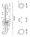
- a disk or plug of filter paper or other material permeable to liquid flow, and lacking any central hole is used both to retain the nozzle-providing component and to prevent its plugging by debris (see, e.g. Fig. 6A ).
- exemplary nozzle assemblies including a specific embodiment of a nozzle-providing component in the form of a nozzle ring, is described below in the context of Figs. 1A-3C .
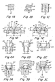
- One exemplary embodiment for fabricating a nozzle ring and a nozzle ring formed thereby is illustrated in Figs. 1A-1E .
- Rings produced by the illustrated method or similar methods and having the characteristics, dimensions and configurations described and illustrated in Figs. 1A-1E are available for fabrication commercially and were obtained from Dynamics Research Corporation (Wilmington, Massachusetts).
- the illustrated method comprises a photolithographic technique, wherein the nozzle rings are formed via the electrodeposition of a metal.
- the exemplary nozzle ring forming method described below is similar in certain respects to that disclosed in U.S. Patent No. 4,954,225 .
- an array of circles 10 is first printed on a substrate 12, and the printed array can be converted to a photolithography mask 14 by conventional techniques.
- mask 14 is used, to produce a congruent array of conductive circles 16 in a thin layer of a photoresist material 18 on a glass plate 20.
- the photolithography mask 14 includes feature forming elements 10 having the shape of a circle, in other embodiments other shapes may be utilized. As explained below, the shape of elements 10 dictates the perimetric shape of the nozzle ring, which is selected to correspond to the cross-sectional shape of the holder in which the nozzle ring will be placed.
- the holder of the nozzle assembly such as a distal tip of the pressure lumen, has a circular cross-section, so that the nozzle rings are formed having a perimetric shape that is circular, as illustrated in Fig. 1E .
- the diameter of elements 10 corresponds to a diameter of a center line 22 of the solid portion of the ring, thereby also affecting the outer diameter OD of the ring 21 and the inner diameter ND of the hole 28 in the ring defining the jet opening of nozzle 30 (see Fig. 1E ).
- these values are selected based upon the desired initial diameter of the liquid jet (for inner diameter ND ) and the inner diameter of the recessed well portion of the holder (for outer diameter OD of ring 21 ). Referring again to Fig. 1B , when the rings are duplicated on an appropriate scale in a photoresist material and it is developed, small, thin circular lines 16 of conductive material are produced on glass plate 20.
- a variety of known electroplating/electrodeposition techniques can potentially be utilized for forming the nozzle rings 21, in the illustrated embodiment, referring to Fig. 1C , plate 20 bearing the conductive circles 16 is placed in a plating bath 32.
- metal for example a nickel-cobalt alloy is plated and allowed to build up uniformly on the conductive regions 16, producing a ring 21 in the shape of a ring torus, wherein the ring torus is hemispherical, such that a cross-section 34 of the ring by a plane containing the longitudinal axis 36 of the hole 38 defining the liquid flow path through the ring, has the shape of a semicircle, as illustrated in Fig. 1D and 1E .
- Nozzle ring 21 After a selected time in plating bath 32, nozzle ring 21 attains a desired thickness H so as to produce a central hole 38 comprising a nozzle 30 with a desired minimum ND comprising a jet opening 28 of nozzle 30.
- Nozzle ring 21, as illustrated in Fig. 1D has the above-described hemispherical shape analogous to a ring torus having a circular cross-section (i.e. like a bagel) which has been sliced in half through a central plan perpendicular to axis 36 of its hole 38 (e.g. like slicing a bagel along its "equator" to make a bagel sandwich).
- the minimum diameter portion of hole 38, which is on flat surface 40 of nozzle ring 21, is, in certain preferred embodiments, used as the jet opening 28 of nozzle 30 in that it is used as the exit for fluid passing through nozzle ring 21, when it is oriented in a functioning nozzle assembly.
- semicircular cross-section 34 is characterized by a radius R having as its origin conductive circle 16 initially formed in the step illustrated Fig. 1B .
- Radius R also, in the illustrated embodiment, defines the height H of nozzle ring 21 and the length of nozzle 30.
- Finished nozzle rings 21 can be detached from plate 20, by conventional means, and, if required, cleaned in preparation for inserting them into holders for forming the inventive nozzle assemblies, as described in further detail in Figs. 2A-3C .
- a detached nozzle ring 21 is illustrated in cross-section in Fig. 1E . Referring to Fig. 1E , a variety of exemplary dimensions are given below, which have been found useful in the practice of certain exemplary embodiments of the invention and for constructing certain exemplary embodiments of the surgical instruments described below and illustrated in Figs. 4A-6D .
- nozzle ring 21 will have an outer diameter OD not greater than about 2.54 mm (0.1 inch) and a height H that is less than the outer diameter.
- the outer diameter OD of nozzle ring 21 is between 0.5 and 2.54 mm (0.02 inch and 0.1 inch)
- outer diameter OD of nozzle ring 21 is between 0.76 and 1.0 mm (0.03 inch and 0.04 inch) and the height H of the ring is between 126 ⁇ m and 0.25 mm (0.005 inch and 0.01 inch).
- the nozzle ring is used for forming a nozzle assembly in a distal tip of a pressure lumen
- which pressure lumen has an inner diameter of 0.76 mm (0.03 inch) and an outer diameter of 1.27 mm (0.05 inch)
- the outer diameter OD of ring 21 is about 0.86 mm (0.034 inch) and the height H of the ring is about 178 ⁇ m (0.007 inch).
- the minimum diameter ND of jet opening 28, which defines the initial diameter of the liquid jet emitted from nozzle ring 21 in operation, is between about 75 ⁇ m and about 0.50 mm (about 0.001 and about 0.02 inch) in certain embodiments is between about 50 ⁇ m and about 0.25 mm (about 0.002 inch and about 0.01 inch) and in certain embodiments is between about 76 ⁇ m and about 178 ⁇ m (about 0.003 and about 0.007 inch). In one exemplary embodiment, inner diameter ND is about 127 ⁇ m (0.005 inch).
- nozzle ring 21 can have extremely smooth liquid contacting surfaces 42 on the upstream side of the nozzle ring and a gradually decreasing inner diameter of nozzle 30, the nozzle ring can have the ability to form highly collimated liquid jets even for relatively low ratios of nozzle length H to jet opening diameter ND.
- a liquid jet formed by a nozzle ring such as nozzle ring 21 can have a cone angle not exceeding 10 degrees, when the ratio of nozzle length H to jet opening diameter ND does not exceed 4, in certain embodiments when the ratio does not exceed 2, and in certain other embodiments where the ratio does not exceed 1.5.
- the liquid jet formed can have a cone angle between 3 degrees and 6 degrees.
- the cone angle refers to the angle formed at the apex of the liquid jet (see Fig. 4C , wherein the cone angle equals 2 x A).
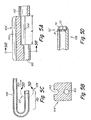
- holder 50 comprises a distal tip of tubing 52, which may be a pressure lumen of a surgical instrument of the invention, which has been bored to produce a recessed well 54 having an inner diameter Z greater than the inner diameter LD of lumen 56 of the tubing 52.
- the base of recessed well 54 comprises a seating surface 58, which, as explained in further detail below, serves to position and orient a nozzle ring or other nozzle-providing component inserted into the holder.
- Seating surface 58 may, optionally, be beveled, as illustrated, to assist in retention and orientation of a nozzle ring, as explained in more detail below.
- the selection of the inner diameter Z of recessed well 54, in comparison with the outer diameter OD of nozzle ring 21, will depend upon the technique utilized for securing the nozzle ring within the holder. For embodiments, such as illustrated in Fig.
- seating surface 58 is located upstream of the nozzle ring, such that pressure applied to the ring, as liquid passes through the nozzle ring in forming the liquid jet, tends to force the nozzle ring away from the seating surface so that the nozzle ring must be strongly retained in recessed well 54 to resist such pressure and force, and wherein the retaining force is provided via press fitting an oversized nozzle ring into recessed well 54, the recessed well of he holder should have an inner diameter Z somewhat less than the outer diameter OD of the nozzle ring as measured when the nozzle ring is in an unstressed configuration prior to insertion of the nozzle ring into the recessed well of the holder.
- the recessed well of he holder should have an inner diameter Z somewhat less than the outer diameter OD of the nozzle ring as measured when the nozzle ring is in an unstressed configuration prior to insertion of the nozzle ring into the recessed well of the holder.
- inner diameter Z of recessed well 54 can be equal to or somewhat larger than outer diameter OD of the nozzle ring 21.
- outer diameter OD of nozzle ring 21 is about 0.86 mm (0.034 inch)
- inner diameter Z of recessed well 54 can be selected to be between about 0.89 mm and about 1.01 mm (about 0.035 and about 0.04 inch).
- the degree of oversize can range between about 1% and about 20%, in certain embodiments between about 5% and about 15%.
- Holder 50 is configured to retain and position a nozzle-providing component in a configuration in which a liquid jet formed by a nozzle of the nozzle-providing component is directed along a desired trajectory.
- a liquid jet formed by the nozzle-providing component when assembled into a nozzle assembly comprising holder 50 , is oriented co-linear with longitudinal axis 60 of pressure lumen 56 , then seating surface 58 should provide a seat coplanar to or geometrically centered about a plane perpendicular to longitudinal axis 60 , as is illustrated in Fig. 2A .
- the inner diameter LD of hole 62 through seating surface 58 is selected, in certain embodiments, to be less than the outer diameter OD of nozzle ring 21.
- LD of hole 62 may be in the range of between about 0.51 mm and about 0.76 mm (about 0.02 and about 0.03 inch).
- the specific dimension selected for LD is, typically, not critical. In certain embodiments, however, it is preferred that LD be greater than the inner diameter ND of jet opening 28 of nozzle ring 21 by at least a factor of about 2, and certain embodiments by at least a factor of about 4, and certain embodiments by at least a factor of about 6.
- LD can be selected to be equal to the inner diameter of lumen 56 of tubing 52 comprising holder 50 .
- Fig. 2B illustrates an alternative embodiment illustrating a holder 50 ', which is substantially similar to holder 50 illustrated in Fig. 2A , except that recessed well 54 is formed in tubing 52 by expanding a distal tip 63 of tubing 52 to form the recessed well 54 having expanded the inner diameter Z' .
- Fig. 2C illustrates yet another embodiment for providing a holder 50" of a nozzle assembly of the invention, wherein the holder comprises a recessed well 54 formed in a plate or side wall of a pressure container, as opposed to at a distal end of a length of tubing, as previously illustrated.
- wall 64 of holder 50" comprises a side wall of high pressure tubing forming a pressure lumen of a surgical instrument provided with a nozzle assembly of the invention.
- recessed well 54 of holder 50" includes a seating surface 58' that is essentially planar, instead of beveled, or slanted as previously illustrated. As illustrated and discussed below in the context of Fig.
- planar seating surfaces can be advantageous for use when the seating surface is positioned downstream of the nozzle-providing component in the nozzle assembly (as illustrated in Fig. 3C ), wherein, when a nozzle ring such as illustrated in Fig. 1E is utilized, the flat surface 40 of the nozzle ring 21 can contact and make sealing contact with seating surface 58'.
- Figs. 3A-3C illustrate several exemplary embodiments for the affixing, securing, and retaining of a nozzle-providing component, such as nozzle ring 21 in a holder to construct an operable nozzle assembly provided according to the invention.
- nozzle assembly 70 comprises holder 50, previously illustrated in Fig. 2A , into which nozzle ring 21 has been inserted.
- Nozzle ring 21 has been inserted into recessed well 54 of holder 50 of nozzle assembly 70 so that its curved surfaces 42 face the high pressure of the upstream side of the fluid flow path through tubing 52.
- nozzle-providing components including a flat side and a side having curvature providing a hole through the nozzle-providing component that is tapered, such as illustrated, it is preferred to orient such a nozzle-providing component so that the curved surfaces face upstream, thereby providing a nozzle having a decreasing inner diameter along the length of the fluid flow path through the nozzle, which can enhance the efficiency and vena contracta effect of the nozzle, as previously described.
- nozzle ring 21 has an outer diameter OD, as measured in a relaxed configuration, that is somewhat larger than the inner diameter Z of recessed well 54 of holder 50.
- nozzle ring 21 can be press-fit into recessed well 54.
- nozzle assembly 70 need not include any additional retaining elements positioned in the holder downstream of the nozzle-providing component (i.e. need not include an optional nozzle retaining element 72 shown in dotted outline and discussed in more detail below).
- nozzle assembly 70 including a nozzle ring 21 having an outer diameter OD when in an unstressed configuration that is somewhat larger than the inner diameter Z of recessed wall 54 of holder 50, is pressure stable at desired operating pressures
- a selected degree of oversize of the outer diameter of nozzle ring 21 enabling the nozzle ring to withstand operating pressures without becoming dislodged from the holder is provided.
- sufficient pressure stability of the nozzle assembly can be provided when the outer diameter OD of the unstressed nozzle ring exceeds the inner diameter ring Z of the recessed well of the holder by less than 10%, and in certain embodiments by an amount between about 1% and 3%. As illustrated in Fig.
- a slanted or beveled seating surface can be formed via a variety of conventional machining techniques and can comprise, for example, a counter bore providing essentially flat angled surfaces, a counter sync bore, providing conical seating surfaces, or a ball seat, providing curved seating surfaces.
- a counter bore providing essentially flat angled surfaces
- a counter sync bore providing conical seating surfaces
- a ball seat providing curved seating surfaces.
- the seating surface be beveled with a counter sync bore, thereby providing conical seating surfaces.
- the nozzle assemblies formed according to the invention be able to withstand desirable operating pressures for forming liquid jets without failure, undesirable leakage, or undesirable misorientation of a liquid jet due to displacement of the nozzle-providing component within the holder.
- a nozzle-providing component it is desirable for a nozzle-providing component to be secured and retained by the holder sufficiently such that the nozzle assembly is able to withstand an internal liquid pressure of at least about 6.9 MPa (1,000 psig) without failure, in certain embodiments, at least about 13.8 MPa (2,000 psig) without failure, in certain embodiments, at least about 20.7 MPa (3,000 psig) without failure, in certain embodiments, at least about 34.4 MPa (5,000 psig) without failure, in certain embodiments, at least about 69 MPa (10,000 psig) without failure, in certain embodiments, at least about 103 MPa (15,000 psig) without failure, in certain embodiments, at least about 207 MPa (30,000 psig) without failure, and yet in other embodiments, at least about 344 MPa (50,000 psig) or more without failure.
- an additional retaining element such as retaining element 72
- retaining element 72 can be provided downstream of the nozzle ring 21 to retain and secure it within the nozzle assembly.
- a retaining element can be any suitable retaining means such as one of those previously mentioned.
- retaining element 72 can comprise a rigid ring or disk press-fit into the recessed well, or a weld or solder bead.
- the retaining element can comprise a region 74 of tubing 52 at its distal tip and downstream of nozzle ring 21 that has been crimped, for example with a crimping die 76 to compress the tubing downstream of the ring so that the nozzle ring is securely contained within nozzle assembly 70'.
- Fig. 3C illustrates an embodiment of a nozzle assembly 70" utilizing holder 50" illustrated and discussed above in the context of Fig. 2C .
- seating surface 58' is located downstream of nozzle ring 21, such that pressurized liquid passing through the nozzle ring and forming the liquid jet tends to force flat surface 40 of the nozzle ring into contact with planar seating surface 58'.
- a retaining element 78 is used to hold nozzle ring 21 in place in recessed well 54 of holder 50". Retaining element 78 may be inserted via press fitting with a swage 80 to provide sufficient retaining force to hold nozzle ring 21 in place.
- a swaging device such as swage 80 could be used to deform the upper edge 82 of recessed well 54 sufficiently to retain nozzle ring 21.
- the retaining element need not be particularly rigid or robust and may comprise elements such as, for example, a porous screen, mesh, disk of filter paper, porous plug, etc.
- Such retaining elements can also, in certain embodiments, provide a desirable filtering function to prevent debris from lodging within a nozzle 30 of nozzle ring 21 during operation.
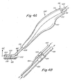
- Figs. 4A-4E illustrate one exemplary embodiment of a surgical instrument provided according to the invention employing an inventive nozzle or nozzle assembly of the invention and/or an inventive nozzle alignment component of the invention.
- the exemplary embodiment illustrated is merely one of a large variety of instruments having a wide variety of configurations and utilizing liquid jets for a wide variety of purposes for which the inventive nozzle or nozzle assemblies and/or nozzle alignment components of the invention can be utilized.
- the liquid jet formed by instrument 100 illustrated in Fig. 4A is utilized for cutting and/or ablating and evacuating tissue 102 of a patient, in other embodiments, the liquid jet may be utilized for other purposes.
- the liquid jet may, in certain embodiments, be utilized solely to drive evacuation and/or for driving rotation of a rotatable component of the instrument, such as a grinding burr or drill.
- a rotatable component of the instrument such as a grinding burr or drill.
- inventive nozzles or nozzle assemblies and/or nozzle alignment components described herein could be utilized for constructing other liquid jet-forming surgical instruments described, for example, commonlyowned U.S. Patent Nos. 5,944,686 ; 6,375,635 and 6,511,493 , and commonly-owned U.S. Patent Publication 2003/0125660 A1 .
- surgical jet instruments such as liquid jet instrument 100, according to the present invention, except as noted below.
- surgical jet instruments according to the present invention in certain embodiments, will include one or more of the above-described inventive nozzles or nozzle assemblies and/or the above-and below-described nozzle alignment components specifically set forth and described herein.
- Figs. 4A and 4B illustrate one embodiment of an assembled surgical handpiece instrument 100 having a distal end 103 including one embodiment of a nozzle alignment component 104 (illustrated in greater detail in Figs. 4C-4E ) provided according to the invention.
- Tissue to be treated with the surgical hand piece is denoted at 102.
- High pressure lumen 106 and evacuation lumen 108 enter handpiece body 110, which in the illustrated embodiment, comprises two mated sections 112 and 114.
- body 110 need not be pressure-tight (i.e., it need not sustain internal pressure).
- body 110 can advantageously include slots or other openings connecting the inside of the body to the surrounding atmosphere to facilitate sterilization of the internal components within the body.
- Components 112 and 114 of hand piece body 110 can be connected together by any convenient means apparent to those of ordinary skill in the art such as including, but not limited to, screw connectors, tab-in-slot connections, adhesives, etc.
- a low pressure evacuation tube 118 and a flexible high pressure hose 120 each of which can be made of a variety of suitable materials as would be apparent to those of ordinary skill in the art.
- each of the above-mentioned tubes is made of a suitable polymeric material.
- Connections within body 110 facilitating fluid communication between high pressure lumen 106 and flexible high pressure hose 120 and between evacuation lumen 108 and low pressure evacuation tube 118 are illustrated in Fig. 4B . While, in the illustrated embodiment high pressure connection 122 and low pressure connection 124 are located within handpiece body 110, in alternative embodiments, the connections can be made either proximally or distally of the handpiece body.
- high pressure lumen 106 and/or evacuation lumen 108 may simply be provided having a length sufficient to extend completely through handpiece body 110 and, alternatively, proximally thereof, such that a separate high pressure line and suction tube need not be provided.
- High pressure connection 122 can comprise a wide variety of high pressure fittings rated to withstand applied operating pressures, which connections are well known to those skilled in the art and are described in greater detail in commonly-owned US Patent No. 6,375,635 .
- low pressure connector 124 can be any of a wide variety of suitable tubing connections well known to those of ordinary skill in the art and as described in the above-mentioned US Patent No. 6,375,635 .
- High pressure hose 120 is connected to a source of pressurized liquid (e.g., a high pressure pump-not shown).
- Evacuation tube 118 can be connected to a suitable container for containing and storing recovered fluid and debris, and, optionally, containing a filtered outlet for entrained air (not shown).
- the evacuation lumen 108 is shaped and positionable to enable it to remove from a surgical site at least a portion of tissue excised by the liquid jet formed by the nozzle during operation.
- the evacuation lumen is shaped and positionable to enable evacuation of essentially all of the liquid comprising the liquid jet from jet receiving opening 126 of the evacuation lumen 108 to the proximal end 116 of the instrument, without the need for an external source of suction.
- evacuation tube 118 can be connected in fluid communication with a suitable source of suction, such as a vacuum pump, aspirator, house vacuum line, etc.
- evacuation efficiency can be enhanced by providing an enlargement in the internal diameter of the evacuation plumbing - for example in evacuation lumen 108 and/or between evacuation lumen 108 and evacuation tube 118 - proximally of jet-receiving opening 126 and any optional constriction forming a venturi (not shown).
- the inner diameter of the evacuation lumen and/or evacuation tube increases from a certain minimum value at a first, distal location to a certain maximum value at a more proximal location. More detail concerning the configuration of the evacuation lumen in such embodiments can be found in commonly-owned U.S. Patent No.
- Such an expansion advantageously provides a diffuser element able to bring about the above-mentioned enhanced suction effect.
- a diffuser may be provide by simply expanding the internal diameter of the evacuation lumen at some point along its length downstream of jet-receiving opening 126.
- such a diffuser may be effected by, for example, making the jet-receiving opening inner diameter somewhat smaller than the inner diameter of the evacuation lumen at any point downstream of the jet-receiving opening.
- an expansion can be provided by interconnecting the evacuation lumen to evacuation tubing 118 having a somewhat larger internal diameter than the evacuation lumen.
- An exemplary expansion of the evacuation line provided at an interconnection between the evacuation lumen and the evacuation tube could be provided by interconnecting an evacuation lumen having a selected internal diameter, for example of between about 0.1 inch and about 0.6 inch, with evacuation tubing having internal diameter exceeding that internal diameter of the evacuation lumen by about 5% to 150% percent, in certain embodiments between about 20% and 120%, depending on the degree of suction enhancement desired.
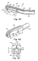
- nozzle alignment component 104 The configuration of the illustrated embodiment of a nozzle alignment component 104 and the liquid jet-forming components at the distal end 103 of surgical instrument 100 are illustrated in greater detail in Figs. 4C-4E.
- Fig. 4C illustrates distal end 103 of instrument 100 in cross section, and Figs. 4D and 4E present more detailed views of nozzle alignment component 104.
- distal tip 128 of pressure lumen 106 in the illustrated embodiment, includes nozzle assembly 70' described above in the context of Fig. 3B .
- nozzle ring 21 of nozzle assembly 70' provides an enhanced vena contracta effect reducing or eliminating fluid pinch that can occur when fluid enters a sharp-edge constriction and does not follow the wall of the nozzle initially such that eddies can form between the outer streamlines and the nozzle wall, thereby decreasing efficiency.
- the streamlines of fluid flow tend to enter the nozzle smoothly and less energy is lost in eddies, leading to increased jet velocity, reduced pressure drop and increased collimation of liquid jet 130 formed by nozzle assembly 70'.
- a liquid jet 130 can be formed that remains collimated over a substantially greater jet length JL than for typical conventional prior art nozzle surgical liquid jet instrument nozzle designs.
- a jet opening diameter ND of about 79 ⁇ m (0.0031 inch)
- a liquid jet 130 that does not disperse to the point where a diameter of the expanded base of the jet 132 is three times as great as the initial diameter ND of the jet for at least about 19 mm (0.75 inch) at supply pressures ranging from about 20.7 MPa (3,000 psig) to over 82.7 MPa (12,000 psig).
- This particular example corresponds to a cone angle (2 ⁇ A as shown in Fig. 4C ) of about 7.1 degrees.
- liquid jet 130 formed by nozzle assembly 70' in liquid jet instrument 100 can have a cone angle less than 10 degrees, and in certain embodiments between 3 degrees and 6 degrees.
- This collimation allows the ability to provide longer liquid jet lengths JL than typically provided in conventional surgical liquid jet instruments, for example, liquid jet lengths not less than 5 mm., and certain embodiments not less than 10 mm., in certain embodiments between 10mm and 20 mm, and in certain embodiments between 13mm and 16 mm.
- nozzle ring 21 Although the semicircular cross-sectional profile of nozzle ring 21, described previously, is believed to be particularly efficient, in certain embodiments, significant improvement, over typical conventional surgical liquid jet nozzle designs, can be obtained utilizing other nozzle configurations in which a liquid flow passage through the nozzle has a diameter that continuously decreases along at least a portion of a liquid flow path through the nozzle. Such tapers can at least partially obviate the effects of flow path sharp edges.
- Such tapered nozzles can be produced by a variety of techniques, such as for example the above-mentioned photolithographic/electrodeposition technique, as well as by techniques such as micro-machining of blanks by various known micro machining methods, etc.
- the evacuation lumen 108 can be configured to have a somewhat different relationship of internal diameter to liquid jet dispersed diameter at the inlet to the evacuation lumen than has been described in Applicant's U.S. Patent No. 6,375,635 .
- the jet-receiving opening when providing an evacuation lumen having a smallest internal diameter at the location of the jet-receiving opening, can be sized so that it has a diameter of about 150% to 300% the diameter of a cross section of the base (e.g.
- the jet-receiving opening can be sized so that it has a diameter between about 150% to about 400%, the diameter of a cross-section of the base of the dispersed jet as it crosses the plane defining the jet-receiving opening, and the minimum opening of the constriction can be sized so that it has a diameter of between about 100% to about 200% the diameter of the cross-section of the base of the dispersed jet as it crosses the plane defining the minimum diameter opening of the constriction.
- an inventive nozzle alignment component 104 can be provided located at or near the distal end 103 of the instrument.
- the nozzle alignment component can be is configured and positioned to connect to the pressure lumen and, upon connection to the pressure lumen to align the nozzle with respect to the evacuation lumen so that the liquid jet enters the jet-receiving opening along a desired trajectory, when the instrument is in operation.
- nozzle alignment component 104 comprises an insert including a groove or channel 140 therein that is sized and configured to contain and secure a distal region of pressure lumen 106.
- Channel 140 may have a width and depth selected to mate with the outer diameter of high pressure lumen 106, such that the high pressure lumen can "snap into” the groove, thereby securely retaining and immobilizing the pressure lumen with respect to the component.
- the connection between the high pressure lumen and the alignment component 104 can be provided or enhanced by securing the high pressure lumen within groove 140 via other connection means, for example adhesives, welding, brazing, straps or clamps, etc.
- the distal end of the high pressure lumen Prior to fabrication, the distal end of the high pressure lumen can be bent, for example on a mandrel, and, upon fabrication, snapped into groove 140 of nozzle alignment component 104.
- a proximal region of nozzle alignment component 104 comprising a downstream end of the insert, includes a section 142 that is sized and configured to be insertable into the jet receiving opening 126 of evacuation lumen 108.
- the outer diameter of section 142 of alignment component 104 may be equal to or slightly greater than the inner diameter of the distal end of evacuation lumen 108.
- downstream evacuation lumen connecting component 142 of nozzle alignment component 104 can be secured within the distal end of evacuation tube 108 via any one of wide variety of suitable means that would be apparent to those skilled in the art.
- a compression sleeve may be provided to securely interconnect downstream portion 142 of alignment component 104 within the distal end of evacuation lumen 108.
- nozzle alignment component 104 further comprises therein an elongated jet interacting channel 144, having a depth DC (see Fig. 4E ) and a length JL, wherein the liquid jet interacting channel 144 includes a longitudinally-oriented opening 146 to the surrounding environment extending along at least a portion of its length and, as is illustrated, along essentially the entire length, of the channel. Adjacent to the longitudinally-oriented jet interacting channel 144 are tissue contacting surfaces 148, which can be apposed to tissue within a surgical operating field during use of the instrument to facilitate the desired depth of cut.
- vent apertures 150 may be provided that are configured and positioned to provide fluid communication between an interior region of channel 144 and the surrounding environment when the longitudinally-oriented opening 146 of channel 144 is occluded by contact with tissue in the operating field during use.
- the particular function and advantage of providing such as jet- interacting channel is described in much greater detail in Applicant's U.S. Patent Publication No. 2003/0125660 A1 , referred to above.
- FIG. 5C illustrates the distal tip 128 of pressure lumen 106 prior to completion of formation of nozzle assembly 70', thus illustrating the appearance of holder 50 prior to insertion of nozzle ring 21 and the securing of the nozzle ring by crimping the distal tip of the pressure lumen, as is illustrated in the finished nozzle assembly 70' illustrated in Fig. 5D .
- Nozzle alignment component 104' is similar to nozzle alignment component 104 previously described except that the pressure lumen securing region of nozzle alignment component 104' positioned upstream of jet interacting channel 144 comprises a lumen 160, which completely surrounds the outer diameter of the distal portion 162 of pressure lumen 106 when the pressure lumen is inserted in to the nozzle alignment component 104'.
- pressure lumen 106 can be bent, on a mandrel, and, the bent distal portion of pressure lumen 106 can then be inserted into nozzle alignment component 104' by sliding the pressure lumen into groove 140 and lumen 160 in the direction of arrow 164.
- Nozzle alignment component 170 is integrally formed in a distal portion of evacuation lumen 108' itself. As such, alignment component 170 is configured and positioned to connect to distal region 162' of pressure lumen 106, but is integrally formed as part of the distal end of evacuation lumen 108', rather than being interconnected to the evacuation as was the case with the configurations previously illustrated in Figs. 4A-5D .
- Nozzle alignment component 170 also illustrates an embodiment utilizing a nozzle assembly 70", previously illustrated and described in the context of Fig. 3C , in which liquid flow through the nozzle assembly tends to force nozzle ring 21 into sealing engagement with seating surfaces 58' of recessed well 54 of holder 50".
- retaining element 78 as illustrated need not be particularly mechanically strong or provide a particularly high level of restraining force.
- retaining element 78 comprises a disk of a porous material, for example filter paper or filter media, inserted upstream of nozzle ring 21.
- distal region 162' of pressure lumen 106 Upon assembly in forming a functional surgical instrument including nozzle alignment component 170, distal region 162' of pressure lumen 106 would be inserted in to the distal end 172 of recessed well 54 and affixed and secured therein, for example by welding, brazing, solder, tubing fittings, etc.
- a jet interacting channel 144' having an opening 146' interacting with a surrounding atmosphere and tissue contacting surfaces 148' can be fabricated from and evacuation lumen via cutting out a segment of the sidewall of the tubing comprising the evacuation lumen, as illustrated, or, in alternative embodiments, by forming a cavity in the side wall of the evacuation lumen by, for example pressing or stamping an indentation into the sidewall.
- Nozzle alignment component 170 and the nozzle assembly configuration and evacuation lumen configuration illustrated in Figs. 6A-6D have the advantage of being simple in configuration and easy to manufacture, because few parts are required, and the configuration can be prepared by machining, casting, or other convenient fabrication methods.
Claims (10)
- Instrument de chirurgie comprenant :un ensemble gicleur comprenant un composant fournissant une buse (21) qui est façonné pour former un jet liquide, etune lumière de pression (56) configurée et positionnée afin de transporter un flux de liquide à l'ensemble gicleur ; caractérisé en ce que :l'ensemble gicleur comprend un support (50) comprenant un évidement creux (54) formé dans la pointe distale de la lumière de pression, ledit support étant configuré pour retenir et positionner le composant fournissant une buse dans l'ensemble gicleur, et en ce que :le composant fournissant une buse comprend un passage du flux de liquide (38) ayant un diamètre qui diminue de manière continue le long d'au moins une partie d'une voie du flux de liquide à travers le passage du flux de liquide.
- Instrument de chirurgie de la revendication 1, dans lequel l'évidement creux présente une surface de portée (58) comprenant un trou dans la surface, dont le trou met le fluide en communication avec la lumière de pression, le trou ayant un diamètre intérieur inférieur à un diamètre extérieur du composant fournissant une buse lorsque le composant fournissant une buse est contenu dans l'évidement creux du support, et dans lequel l'évidement creux du support présente un diamètre intérieur au moins aussi grand que le diamètre extérieur du composant fournissant une buse lorsque le composant fournissant une buse est contenu dans l'évidement creux du support.
- Instrument de chirurgie de la revendication 1, dans lequel
un rapport d'une longueur de voie du flux de liquide à travers une buse de composant fournissant une buse sur un diamètre intérieur minimal d'un orifice formant un jet de la buse ne dépasse pas 4 ; et dans lequel
le jet liquide formé par l'instrument lorsqu'il est en fonctionnement présente un angle de cône maximal ne dépassant pas 10 degrés. - Instrument de chirurgie de la revendication 1, comprenant en outre :une lumière d'évacuation (108) comprenant une ouverture recevant le jet (126) située à l'opposé d'une buse du composant fournissant une buse afin de recevoir au moins une partie du jet liquide émis par la buse, lorsque l'instrument est en fonctionnement, et qui est configurée et positionnée pour transporter un flux de liquide loin de l'ouverture recevant le jet ; etun composant d'alignement de buse (104) situé au niveau ou à proximité de l'extrémité distale de l'instrument qui est configuré et positionné pour se relier à la lumière de pression et à la lumière d'évacuation et, pour aligner suite au raccordement à la lumière de pression et à la lumière d'évacuation, la buse par rapport à la lumière d'évacuation de sorte que le jet liquide pénètre dans l'ouverture recevant le jet le long d'une trajectoire sélectionnée, lorsque l'instrument est en fonctionnement.
- Instrument de chirurgie de la revendication 4, dans lequel le composant fournissant une buse possède une forme d'un tore en anneau et dans lequel le tore en anneau est hémisphérique, de sorte qu'une section transversale du tore en anneau, suivant un plan contenant l'axe central longitudinal du trou du tore en anneau, qui comprend le passage du flux de liquide, présente la forme d'un demi-cercle.
- Instrument de chirurgie de la revendication 2, dans lequel le composant fournissant une buse est suffisamment fixé et retenu par le support de sorte que l'ensemble gicleur soit capable de résister à une pression interne de liquide d'au moins 20,7 MPa (3,000 Psig) sans défaillance.
- Instrument de chirurgie de la revendication 2, dans lequel le support est configuré pour maintenir et positionner le composant fournissant une buse dans une configuration où le jet liquide formé par une buse du composant fournissant une buse est dirigé le long d'une trajectoire souhaitée.
- Instrument de chirurgie de la revendication 7, dans lequel la surface de portée est située en aval du composant fournissant une buse, de sorte que le liquide sous pression passant à travers le composant fournissant une buse lors de la formation du jet liquide tende à forcer une surface du composant fournissant une buse pour se mettre en contact avec la surface de portée.
- Instrument de chirurgie de la revendication 8, dans lequel l'ensemble gicleur comprend en outre un élément de retenue positionné dans le support en amont du composant fournissant une buse.
- Instrument de chirurgie de la revendication 9, dans lequel l'élément de retenue comprend un tamis poreux, une maille, ou un disque de papier-filtre.
Applications Claiming Priority (5)
| Application Number | Priority Date | Filing Date | Title |
|---|---|---|---|
| US44434403P | 2003-01-31 | 2003-01-31 | |
| US444344P | 2003-01-31 | ||
| US10/695,632 US8162966B2 (en) | 2002-10-25 | 2003-10-27 | Surgical devices incorporating liquid jet assisted tissue manipulation and methods for their use |
| US695632 | 2003-10-27 | ||
| PCT/US2004/002893 WO2004069064A2 (fr) | 2003-01-31 | 2004-02-02 | Ensembles de buse pour instruments chirurgicaux a jet liquide et instruments chirurgicaux utilisant les ensembles de buses |
Publications (2)
| Publication Number | Publication Date |
|---|---|
| EP1589884A2 EP1589884A2 (fr) | 2005-11-02 |
| EP1589884B1 true EP1589884B1 (fr) | 2012-12-19 |
Family
ID=32853369
Family Applications (1)
| Application Number | Title | Priority Date | Filing Date |
|---|---|---|---|
| EP04707378A Expired - Lifetime EP1589884B1 (fr) | 2003-01-31 | 2004-02-02 | Ensembles de buse pour instruments chirurgicaux a jet liquide et instruments chirurgicaux utilisant les ensembles de buses |
Country Status (6)
| Country | Link |
|---|---|
| US (2) | US8162966B2 (fr) |
| EP (1) | EP1589884B1 (fr) |
| JP (2) | JP2006517832A (fr) |
| AU (1) | AU2004209990B2 (fr) |
| CA (1) | CA2554930C (fr) |
| WO (1) | WO2004069064A2 (fr) |
Families Citing this family (253)
| Publication number | Priority date | Publication date | Assignee | Title |
|---|---|---|---|---|
| US6375635B1 (en) | 1999-05-18 | 2002-04-23 | Hydrocision, Inc. | Fluid jet surgical instruments |
| ATE367527T1 (de) | 2001-04-27 | 2007-08-15 | Hydrocision Inc | Hochdruckeinwegpumpenkassette zur anwendung auf medizinischem gebiet |
| US10835307B2 (en) | 2001-06-12 | 2020-11-17 | Ethicon Llc | Modular battery powered handheld surgical instrument containing elongated multi-layered shaft |
| CA2493238C (fr) | 2001-08-08 | 2007-10-23 | Hydrocision, Inc. | Dispositif medical equipe d'une piece a main a demontage rapide et a pression elevee |
| ES2290358T3 (es) | 2001-11-21 | 2008-02-16 | Hydrocision, Inc. | Instrumentos quirurgicos con chorro de liquido, que incorporan aberturas del canal alineadas a lo largo del haz del chorro. |
| US10363061B2 (en) | 2002-10-25 | 2019-07-30 | Hydrocision, Inc. | Nozzle assemblies for liquid jet surgical instruments and surgical instruments for employing the nozzle assemblies |
| US8162966B2 (en) | 2002-10-25 | 2012-04-24 | Hydrocision, Inc. | Surgical devices incorporating liquid jet assisted tissue manipulation and methods for their use |
| US7794408B2 (en) | 2003-03-28 | 2010-09-14 | Ethicon, Inc. | Tissue collection device and methods |
| US7611473B2 (en) | 2003-09-11 | 2009-11-03 | Ethicon, Inc. | Tissue extraction and maceration device |
| US8034003B2 (en) | 2003-09-11 | 2011-10-11 | Depuy Mitek, Inc. | Tissue extraction and collection device |
| US8182501B2 (en) | 2004-02-27 | 2012-05-22 | Ethicon Endo-Surgery, Inc. | Ultrasonic surgical shears and method for sealing a blood vessel using same |
| US20050197644A1 (en) * | 2004-03-03 | 2005-09-08 | Waychoff Challen W.Ii | Colon hydrotherapy device |
| DE102004020855B4 (de) * | 2004-04-28 | 2009-06-10 | Erbe Elektromedizin Gmbh | Applikator für die Wasserstrahl-Chirurgie |
| US7641688B2 (en) | 2004-09-16 | 2010-01-05 | Evera Medical, Inc. | Tissue augmentation device |
| AU2005295010B2 (en) | 2004-10-08 | 2012-05-31 | Ethicon Endo-Surgery, Inc. | Ultrasonic surgical instrument |
| US20060129086A1 (en) * | 2004-12-13 | 2006-06-15 | Depuy Mitek, Inc. | Interchangeable tissue macerating and sculpting methods and devices |
| WO2006066160A1 (fr) * | 2004-12-14 | 2006-06-22 | Hydrocision, Inc. | Instruments chirurgicaux a jet de liquide |
| US20060142775A1 (en) * | 2004-12-29 | 2006-06-29 | Depuy Mitek, Inc. | Surgical tool with cannulated rotary tip |
| US20070191713A1 (en) | 2005-10-14 | 2007-08-16 | Eichmann Stephen E | Ultrasonic device for cutting and coagulating |
| US7621930B2 (en) | 2006-01-20 | 2009-11-24 | Ethicon Endo-Surgery, Inc. | Ultrasound medical instrument having a medical ultrasonic blade |
| DE202006004045U1 (de) * | 2006-03-15 | 2007-08-02 | Synthes Gmbh | Chirurgisches Schneidwerkzeug |
| US10835355B2 (en) | 2006-04-20 | 2020-11-17 | Sonendo, Inc. | Apparatus and methods for treating root canals of teeth |
| EP2015698B1 (fr) | 2006-04-20 | 2017-11-15 | Sonendo, Inc. | Appareil pour traiter des canaux radiculaires de dents |
| EP2019628A4 (fr) * | 2006-04-25 | 2014-03-05 | Hydrocision Inc | Instrument chirurgical électroformé à jet de liquide |
| US7980854B2 (en) | 2006-08-24 | 2011-07-19 | Medical Dental Advanced Technologies Group, L.L.C. | Dental and medical treatments and procedures |
| US20080103412A1 (en) | 2006-11-01 | 2008-05-01 | Yem Chin | Removing Tissue |
| DE202006018986U1 (de) * | 2006-12-16 | 2008-04-17 | Human Med Ag | Applikator für eine Wasserstrahleinrichtung, insbesondere zur Behandlung von Wunden und Geschwüren |
| AU2007342018A1 (en) * | 2006-12-29 | 2008-07-10 | Richard Bevier | Wound bed preparation |
| CA2677343C (fr) | 2007-02-05 | 2016-06-21 | Boston Scientific Limited | Appareil et procede de thrombectomie |
| US8142461B2 (en) | 2007-03-22 | 2012-03-27 | Ethicon Endo-Surgery, Inc. | Surgical instruments |
| US8911460B2 (en) | 2007-03-22 | 2014-12-16 | Ethicon Endo-Surgery, Inc. | Ultrasonic surgical instruments |
| US20080234709A1 (en) | 2007-03-22 | 2008-09-25 | Houser Kevin L | Ultrasonic surgical instrument and cartilage and bone shaping blades therefor |
| US8057498B2 (en) | 2007-11-30 | 2011-11-15 | Ethicon Endo-Surgery, Inc. | Ultrasonic surgical instrument blades |
| US8226675B2 (en) | 2007-03-22 | 2012-07-24 | Ethicon Endo-Surgery, Inc. | Surgical instruments |
| US9271751B2 (en) * | 2007-05-29 | 2016-03-01 | Ethicon Endo-Surgery, Llc | Ultrasonic surgical system |
| DE202007008972U1 (de) * | 2007-06-27 | 2008-11-06 | Human Med Ag | Vorrichtung zur chirurgischen Behandlung biologischer Strukturen |
| US8808319B2 (en) | 2007-07-27 | 2014-08-19 | Ethicon Endo-Surgery, Inc. | Surgical instruments |
| US8882791B2 (en) | 2007-07-27 | 2014-11-11 | Ethicon Endo-Surgery, Inc. | Ultrasonic surgical instruments |
| US8523889B2 (en) | 2007-07-27 | 2013-09-03 | Ethicon Endo-Surgery, Inc. | Ultrasonic end effectors with increased active length |
| US8348967B2 (en) | 2007-07-27 | 2013-01-08 | Ethicon Endo-Surgery, Inc. | Ultrasonic surgical instruments |
| US9044261B2 (en) | 2007-07-31 | 2015-06-02 | Ethicon Endo-Surgery, Inc. | Temperature controlled ultrasonic surgical instruments |
| US8512365B2 (en) | 2007-07-31 | 2013-08-20 | Ethicon Endo-Surgery, Inc. | Surgical instruments |
| US8252012B2 (en) | 2007-07-31 | 2012-08-28 | Ethicon Endo-Surgery, Inc. | Ultrasonic surgical instrument with modulator |
| US8430898B2 (en) | 2007-07-31 | 2013-04-30 | Ethicon Endo-Surgery, Inc. | Ultrasonic surgical instruments |
| US8623027B2 (en) | 2007-10-05 | 2014-01-07 | Ethicon Endo-Surgery, Inc. | Ergonomic surgical instruments |
| US10010339B2 (en) | 2007-11-30 | 2018-07-03 | Ethicon Llc | Ultrasonic surgical blades |
| US7901423B2 (en) | 2007-11-30 | 2011-03-08 | Ethicon Endo-Surgery, Inc. | Folded ultrasonic end effectors with increased active length |
| US20090198329A1 (en) | 2008-02-01 | 2009-08-06 | Kesten Randy J | Breast implant with internal flow dampening |
| US8088163B1 (en) | 2008-02-06 | 2012-01-03 | Kleiner Jeffrey B | Tools and methods for spinal fusion |
| WO2009117159A2 (fr) * | 2008-03-20 | 2009-09-24 | Carrier Corporation | Echangeur de chaleur à micro-canaux qui convient au pliage |
| DE102008025233A1 (de) * | 2008-05-27 | 2009-12-03 | Erbe Elektromedizin Gmbh | Wasserstrahlchirurgieinstrument |
| EP2303155A4 (fr) * | 2008-06-23 | 2014-08-27 | Allosource | Chambre aseptique de nettoyage à l eau sous haute pression |
| US9675411B2 (en) * | 2008-07-15 | 2017-06-13 | Biosense Webster, Inc. | Catheter with perforated tip |
| WO2010006564A1 (fr) * | 2008-07-15 | 2010-01-21 | Human Med Ag | Dispositif pour le traitement chirurgical de structures biologiques |
| AU2014262259B2 (en) * | 2008-07-15 | 2016-09-22 | Biosense Webster, Inc. | Catheter with perforated tip |
| US8058771B2 (en) | 2008-08-06 | 2011-11-15 | Ethicon Endo-Surgery, Inc. | Ultrasonic device for cutting and coagulating with stepped output |
| US9089360B2 (en) | 2008-08-06 | 2015-07-28 | Ethicon Endo-Surgery, Inc. | Devices and techniques for cutting and coagulating tissue |
| USD853560S1 (en) | 2008-10-09 | 2019-07-09 | Nuvasive, Inc. | Spinal implant insertion device |
| US9510854B2 (en) * | 2008-10-13 | 2016-12-06 | Boston Scientific Scimed, Inc. | Thrombectomy catheter with control box having pressure/vacuum valve for synchronous aspiration and fluid irrigation |
| US8366748B2 (en) | 2008-12-05 | 2013-02-05 | Kleiner Jeffrey | Apparatus and method of spinal implant and fusion |
| US9717403B2 (en) | 2008-12-05 | 2017-08-01 | Jeffrey B. Kleiner | Method and apparatus for performing retro peritoneal dissection |
| US8864654B2 (en) | 2010-04-20 | 2014-10-21 | Jeffrey B. Kleiner | Method and apparatus for performing retro peritoneal dissection |
| US8936598B2 (en) * | 2009-01-14 | 2015-01-20 | DePuy Synthes Products, LLC | Spinal disc preparation tool |
| US20100180738A1 (en) * | 2009-01-22 | 2010-07-22 | Michael Tavger | Liquid cutting device |
| US9247943B1 (en) | 2009-02-06 | 2016-02-02 | Kleiner Intellectual Property, Llc | Devices and methods for preparing an intervertebral workspace |
| USD656610S1 (en) | 2009-02-06 | 2012-03-27 | Kleiner Jeffrey B | Spinal distraction instrument |
| CA2876807C (fr) * | 2009-05-18 | 2016-07-12 | Teleflex Medical Incorporated | Methode et dispositifs utilises pour une chirurgie tres peu invasive |
| US9700339B2 (en) | 2009-05-20 | 2017-07-11 | Ethicon Endo-Surgery, Inc. | Coupling arrangements and methods for attaching tools to ultrasonic surgical instruments |
| US8344596B2 (en) | 2009-06-24 | 2013-01-01 | Ethicon Endo-Surgery, Inc. | Transducer arrangements for ultrasonic surgical instruments |
| US8461744B2 (en) | 2009-07-15 | 2013-06-11 | Ethicon Endo-Surgery, Inc. | Rotating transducer mount for ultrasonic surgical instruments |
| US9017326B2 (en) | 2009-07-15 | 2015-04-28 | Ethicon Endo-Surgery, Inc. | Impedance monitoring apparatus, system, and method for ultrasonic surgical instruments |
| US8663220B2 (en) | 2009-07-15 | 2014-03-04 | Ethicon Endo-Surgery, Inc. | Ultrasonic surgical instruments |
| USD723682S1 (en) | 2013-05-03 | 2015-03-03 | Spinal Surgical Strategies, Llc | Bone graft delivery tool |
| USD750249S1 (en) | 2014-10-20 | 2016-02-23 | Spinal Surgical Strategies, Llc | Expandable fusion cage |
| US8906028B2 (en) | 2009-09-18 | 2014-12-09 | Spinal Surgical Strategies, Llc | Bone graft delivery device and method of using the same |
| US20170238984A1 (en) | 2009-09-18 | 2017-08-24 | Spinal Surgical Strategies, Llc | Bone graft delivery device with positioning handle |
| US9186193B2 (en) | 2009-09-18 | 2015-11-17 | Spinal Surgical Strategies, Llc | Fusion cage with combined biological delivery system |
| US9060877B2 (en) | 2009-09-18 | 2015-06-23 | Spinal Surgical Strategies, Llc | Fusion cage with combined biological delivery system |
| US10245159B1 (en) | 2009-09-18 | 2019-04-02 | Spinal Surgical Strategies, Llc | Bone graft delivery system and method for using same |
| US9173694B2 (en) | 2009-09-18 | 2015-11-03 | Spinal Surgical Strategies, Llc | Fusion cage with combined biological delivery system |
| US9629729B2 (en) | 2009-09-18 | 2017-04-25 | Spinal Surgical Strategies, Llc | Biological delivery system with adaptable fusion cage interface |
| US8685031B2 (en) | 2009-09-18 | 2014-04-01 | Spinal Surgical Strategies, Llc | Bone graft delivery system |
| US10973656B2 (en) | 2009-09-18 | 2021-04-13 | Spinal Surgical Strategies, Inc. | Bone graft delivery system and method for using same |
| US10441345B2 (en) | 2009-10-09 | 2019-10-15 | Ethicon Llc | Surgical generator for ultrasonic and electrosurgical devices |
| US11090104B2 (en) | 2009-10-09 | 2021-08-17 | Cilag Gmbh International | Surgical generator for ultrasonic and electrosurgical devices |
| US8951248B2 (en) | 2009-10-09 | 2015-02-10 | Ethicon Endo-Surgery, Inc. | Surgical generator for ultrasonic and electrosurgical devices |
| US9168054B2 (en) | 2009-10-09 | 2015-10-27 | Ethicon Endo-Surgery, Inc. | Surgical generator for ultrasonic and electrosurgical devices |
| USRE47996E1 (en) | 2009-10-09 | 2020-05-19 | Ethicon Llc | Surgical generator for ultrasonic and electrosurgical devices |
| US9492244B2 (en) | 2009-11-13 | 2016-11-15 | Sonendo, Inc. | Liquid jet apparatus and methods for dental treatments |
| US8337175B2 (en) | 2009-12-22 | 2012-12-25 | Smith & Nephew, Inc. | Disposable pumping system and coupler |
| US8382782B2 (en) | 2010-02-11 | 2013-02-26 | Ethicon Endo-Surgery, Inc. | Ultrasonic surgical instruments with partially rotating blade and fixed pad arrangement |
| US8469981B2 (en) | 2010-02-11 | 2013-06-25 | Ethicon Endo-Surgery, Inc. | Rotatable cutting implement arrangements for ultrasonic surgical instruments |
| US8419759B2 (en) | 2010-02-11 | 2013-04-16 | Ethicon Endo-Surgery, Inc. | Ultrasonic surgical instrument with comb-like tissue trimming device |
| US8579928B2 (en) | 2010-02-11 | 2013-11-12 | Ethicon Endo-Surgery, Inc. | Outer sheath and blade arrangements for ultrasonic surgical instruments |
| US9259234B2 (en) | 2010-02-11 | 2016-02-16 | Ethicon Endo-Surgery, Llc | Ultrasonic surgical instruments with rotatable blade and hollow sheath arrangements |
| US8961547B2 (en) | 2010-02-11 | 2015-02-24 | Ethicon Endo-Surgery, Inc. | Ultrasonic surgical instruments with moving cutting implement |
| US8486096B2 (en) | 2010-02-11 | 2013-07-16 | Ethicon Endo-Surgery, Inc. | Dual purpose surgical instrument for cutting and coagulating tissue |
| US8323302B2 (en) | 2010-02-11 | 2012-12-04 | Ethicon Endo-Surgery, Inc. | Methods of using ultrasonically powered surgical instruments with rotatable cutting implements |
| US8951272B2 (en) | 2010-02-11 | 2015-02-10 | Ethicon Endo-Surgery, Inc. | Seal arrangements for ultrasonically powered surgical instruments |
| US8531064B2 (en) | 2010-02-11 | 2013-09-10 | Ethicon Endo-Surgery, Inc. | Ultrasonically powered surgical instruments with rotating cutting implement |
| US9949791B2 (en) | 2010-04-26 | 2018-04-24 | Biosense Webster, Inc. | Irrigated catheter with internal position sensor |
| US9943363B2 (en) | 2010-04-28 | 2018-04-17 | Biosense Webster, Inc. | Irrigated ablation catheter with improved fluid flow |
| US9510894B2 (en) | 2010-04-28 | 2016-12-06 | Biosense Webster (Israel) Ltd. | Irrigated ablation catheter having irrigation ports with reduced hydraulic resistance |
| US9943362B2 (en) | 2010-04-28 | 2018-04-17 | Biosense Webster, Inc. | Irrigated ablation catheter with improved fluid flow |
| GB2480498A (en) | 2010-05-21 | 2011-11-23 | Ethicon Endo Surgery Inc | Medical device comprising RF circuitry |
| US10219826B2 (en) | 2010-07-14 | 2019-03-05 | Seg-Way Orthopaedics, Inc. | Method and apparatus for endoscopic ligament release |
| US8795327B2 (en) | 2010-07-22 | 2014-08-05 | Ethicon Endo-Surgery, Inc. | Electrosurgical instrument with separate closure and cutting members |
| US9192431B2 (en) | 2010-07-23 | 2015-11-24 | Ethicon Endo-Surgery, Inc. | Electrosurgical cutting and sealing instrument |
| CN103347462B (zh) | 2010-10-21 | 2017-05-10 | 索南多股份有限公司 | 用于牙髓治疗的设备、方法和组合 |
| JP5862020B2 (ja) * | 2011-02-28 | 2016-02-16 | セイコーエプソン株式会社 | 流体噴射装置 |
| US8968293B2 (en) | 2011-04-12 | 2015-03-03 | Covidien Lp | Systems and methods for calibrating power measurements in an electrosurgical generator |
| US9259265B2 (en) | 2011-07-22 | 2016-02-16 | Ethicon Endo-Surgery, Llc | Surgical instruments for tensioning tissue |
| USD691265S1 (en) | 2011-08-23 | 2013-10-08 | Covidien Ag | Control assembly for portable surgical device |
| EP3011918B1 (fr) | 2011-12-03 | 2018-07-25 | DePuy Synthes Products, Inc. | Têtes de coupe sans danger et systèmes permettant de retirer rapidement un tissu cible |
| US9238122B2 (en) | 2012-01-26 | 2016-01-19 | Covidien Lp | Thrombectomy catheter systems |
| EP2811932B1 (fr) | 2012-02-10 | 2019-06-26 | Ethicon LLC | Instrument chirurgical robotisé |
| IN2014DN08727A (fr) | 2012-03-22 | 2015-05-22 | Sonendo Inc | |
| US9724118B2 (en) | 2012-04-09 | 2017-08-08 | Ethicon Endo-Surgery, Llc | Techniques for cutting and coagulating tissue for ultrasonic surgical instruments |
| US9439668B2 (en) | 2012-04-09 | 2016-09-13 | Ethicon Endo-Surgery, Llc | Switch arrangements for ultrasonic surgical instruments |
| US9237921B2 (en) | 2012-04-09 | 2016-01-19 | Ethicon Endo-Surgery, Inc. | Devices and techniques for cutting and coagulating tissue |
| US9241731B2 (en) | 2012-04-09 | 2016-01-26 | Ethicon Endo-Surgery, Inc. | Rotatable electrical connection for ultrasonic surgical instruments |
| US9226766B2 (en) | 2012-04-09 | 2016-01-05 | Ethicon Endo-Surgery, Inc. | Serial communication protocol for medical device |
| US10631962B2 (en) | 2012-04-13 | 2020-04-28 | Sonendo, Inc. | Apparatus and methods for cleaning teeth and gingival pockets |
| US20140005705A1 (en) | 2012-06-29 | 2014-01-02 | Ethicon Endo-Surgery, Inc. | Surgical instruments with articulating shafts |
| US9393037B2 (en) | 2012-06-29 | 2016-07-19 | Ethicon Endo-Surgery, Llc | Surgical instruments with articulating shafts |
| US9326788B2 (en) | 2012-06-29 | 2016-05-03 | Ethicon Endo-Surgery, Llc | Lockout mechanism for use with robotic electrosurgical device |
| US9820768B2 (en) | 2012-06-29 | 2017-11-21 | Ethicon Llc | Ultrasonic surgical instruments with control mechanisms |
| US9226767B2 (en) | 2012-06-29 | 2016-01-05 | Ethicon Endo-Surgery, Inc. | Closed feedback control for electrosurgical device |
| US9351754B2 (en) | 2012-06-29 | 2016-05-31 | Ethicon Endo-Surgery, Llc | Ultrasonic surgical instruments with distally positioned jaw assemblies |
| US9283045B2 (en) | 2012-06-29 | 2016-03-15 | Ethicon Endo-Surgery, Llc | Surgical instruments with fluid management system |
| US20140005702A1 (en) | 2012-06-29 | 2014-01-02 | Ethicon Endo-Surgery, Inc. | Ultrasonic surgical instruments with distally positioned transducers |
| US9198714B2 (en) | 2012-06-29 | 2015-12-01 | Ethicon Endo-Surgery, Inc. | Haptic feedback devices for surgical robot |
| US9408622B2 (en) | 2012-06-29 | 2016-08-09 | Ethicon Endo-Surgery, Llc | Surgical instruments with articulating shafts |
| US9492224B2 (en) | 2012-09-28 | 2016-11-15 | EthiconEndo-Surgery, LLC | Multi-function bi-polar forceps |
| US10201365B2 (en) | 2012-10-22 | 2019-02-12 | Ethicon Llc | Surgeon feedback sensing and display methods |
| US9095367B2 (en) | 2012-10-22 | 2015-08-04 | Ethicon Endo-Surgery, Inc. | Flexible harmonic waveguides/blades for surgical instruments |
| US9186164B2 (en) | 2012-10-25 | 2015-11-17 | Gyrus Acmi, Inc. | Impact lithotripsy tip |
| US9168099B2 (en) | 2012-10-25 | 2015-10-27 | Gyrus Acmi, Inc. | Lithotripsy apparatus using a flexible endoscope |
| US20140135804A1 (en) | 2012-11-15 | 2014-05-15 | Ethicon Endo-Surgery, Inc. | Ultrasonic and electrosurgical devices |
| US10363120B2 (en) | 2012-12-20 | 2019-07-30 | Sonendo, Inc. | Apparatus and methods for cleaning teeth and root canals |
| EP3572036B1 (fr) | 2012-12-20 | 2021-05-26 | Sonendo, Inc. | Appareil de nettoyage de dents et de canaux radiculaires |
| EP2951019B1 (fr) | 2013-02-04 | 2018-12-19 | Sonendo, Inc. | Système de traitement dentaire |
| US10226273B2 (en) | 2013-03-14 | 2019-03-12 | Ethicon Llc | Mechanical fasteners for use with surgical energy devices |
| US9241728B2 (en) | 2013-03-15 | 2016-01-26 | Ethicon Endo-Surgery, Inc. | Surgical instrument with multiple clamping mechanisms |
| US9867636B2 (en) * | 2013-03-15 | 2018-01-16 | The Regents Of The University Of California | Method, apparatus, and a system for a water jet |
| CA2910809A1 (fr) | 2013-05-01 | 2014-11-06 | Sonendo, Inc. | Appareil et procedes pour traiter des dents |
| ES2855198T3 (es) | 2013-05-09 | 2021-09-23 | Gyrus Acmi Inc D B A Olympus Surgical Tech America | Litotriptor oscilante multimodal |
| EP3013277B1 (fr) | 2013-06-26 | 2023-07-19 | Sonendo, Inc. | Appareil et procédés de plombage dentaire et de dévitalisation |
| CN105578975A (zh) | 2013-07-19 | 2016-05-11 | 欧罗波罗斯医学有限公司 | 用于真空辅助式组织移除系统的防堵塞装置 |
| US9814514B2 (en) | 2013-09-13 | 2017-11-14 | Ethicon Llc | Electrosurgical (RF) medical instruments for cutting and coagulating tissue |
| US9265926B2 (en) | 2013-11-08 | 2016-02-23 | Ethicon Endo-Surgery, Llc | Electrosurgical devices |
| GB2521228A (en) | 2013-12-16 | 2015-06-17 | Ethicon Endo Surgery Inc | Medical device |
| GB2521229A (en) | 2013-12-16 | 2015-06-17 | Ethicon Endo Surgery Inc | Medical device |
| US9795436B2 (en) | 2014-01-07 | 2017-10-24 | Ethicon Llc | Harvesting energy from a surgical generator |
| US9554854B2 (en) | 2014-03-18 | 2017-01-31 | Ethicon Endo-Surgery, Llc | Detecting short circuits in electrosurgical medical devices |
| US10092310B2 (en) | 2014-03-27 | 2018-10-09 | Ethicon Llc | Electrosurgical devices |
| US10463421B2 (en) | 2014-03-27 | 2019-11-05 | Ethicon Llc | Two stage trigger, clamp and cut bipolar vessel sealer |
| US9737355B2 (en) | 2014-03-31 | 2017-08-22 | Ethicon Llc | Controlling impedance rise in electrosurgical medical devices |
| US9655597B2 (en) * | 2014-03-31 | 2017-05-23 | Cesar C. Carriazo | Medical hollow needle |
| US9248221B2 (en) | 2014-04-08 | 2016-02-02 | Incuvate, Llc | Aspiration monitoring system and method |
| US9433427B2 (en) | 2014-04-08 | 2016-09-06 | Incuvate, Llc | Systems and methods for management of thrombosis |
| US9913680B2 (en) | 2014-04-15 | 2018-03-13 | Ethicon Llc | Software algorithms for electrosurgical instruments |
| US9883877B2 (en) | 2014-05-19 | 2018-02-06 | Walk Vascular, Llc | Systems and methods for removal of blood and thrombotic material |
| US10285724B2 (en) | 2014-07-31 | 2019-05-14 | Ethicon Llc | Actuation mechanisms and load adjustment assemblies for surgical instruments |
| US10639092B2 (en) | 2014-12-08 | 2020-05-05 | Ethicon Llc | Electrode configurations for surgical instruments |
| US10245095B2 (en) | 2015-02-06 | 2019-04-02 | Ethicon Llc | Electrosurgical instrument with rotation and articulation mechanisms |
| US10321950B2 (en) | 2015-03-17 | 2019-06-18 | Ethicon Llc | Managing tissue treatment |
| US10342602B2 (en) | 2015-03-17 | 2019-07-09 | Ethicon Llc | Managing tissue treatment |
| US10595929B2 (en) | 2015-03-24 | 2020-03-24 | Ethicon Llc | Surgical instruments with firing system overload protection mechanisms |
| EP3097876B1 (fr) | 2015-05-29 | 2021-03-17 | Medaxis Ag | Élement de buse pour projeter un jet d'eau |
| US10034684B2 (en) | 2015-06-15 | 2018-07-31 | Ethicon Llc | Apparatus and method for dissecting and coagulating tissue |
| US11020140B2 (en) | 2015-06-17 | 2021-06-01 | Cilag Gmbh International | Ultrasonic surgical blade for use with ultrasonic surgical instruments |
| US10034704B2 (en) | 2015-06-30 | 2018-07-31 | Ethicon Llc | Surgical instrument with user adaptable algorithms |
| US10898256B2 (en) | 2015-06-30 | 2021-01-26 | Ethicon Llc | Surgical system with user adaptable techniques based on tissue impedance |
| US10357303B2 (en) | 2015-06-30 | 2019-07-23 | Ethicon Llc | Translatable outer tube for sealing using shielded lap chole dissector |
| US11051873B2 (en) | 2015-06-30 | 2021-07-06 | Cilag Gmbh International | Surgical system with user adaptable techniques employing multiple energy modalities based on tissue parameters |
| US11129669B2 (en) | 2015-06-30 | 2021-09-28 | Cilag Gmbh International | Surgical system with user adaptable techniques based on tissue type |
| US11141213B2 (en) | 2015-06-30 | 2021-10-12 | Cilag Gmbh International | Surgical instrument with user adaptable techniques |
| US10154852B2 (en) | 2015-07-01 | 2018-12-18 | Ethicon Llc | Ultrasonic surgical blade with improved cutting and coagulation features |
| US10702292B2 (en) | 2015-08-28 | 2020-07-07 | Incuvate, Llc | Aspiration monitoring system and method |
| US10561440B2 (en) | 2015-09-03 | 2020-02-18 | Vesatek, Llc | Systems and methods for manipulating medical devices |
| US10687884B2 (en) | 2015-09-30 | 2020-06-23 | Ethicon Llc | Circuits for supplying isolated direct current (DC) voltage to surgical instruments |
| US20170100142A1 (en) | 2015-10-09 | 2017-04-13 | Incuvate, Llc | Systems and methods for management of thrombosis |
| US10595930B2 (en) | 2015-10-16 | 2020-03-24 | Ethicon Llc | Electrode wiping surgical device |
| USD797290S1 (en) | 2015-10-19 | 2017-09-12 | Spinal Surgical Strategies, Llc | Bone graft delivery tool |
| JP6559889B2 (ja) * | 2015-10-28 | 2019-08-14 | ボストン サイエンティフィック サイムド,インコーポレイテッドBoston Scientific Scimed,Inc. | 格納式の組織切断デバイス |
| US10287543B2 (en) * | 2015-11-19 | 2019-05-14 | Miltenyi Biotec, Gmbh | Process and device for isolating cells from biological tissue |
| US10842467B2 (en) * | 2015-12-15 | 2020-11-24 | Portal Instruments, Inc. | Biospecimen extraction apparatus |
| US10226263B2 (en) | 2015-12-23 | 2019-03-12 | Incuvate, Llc | Aspiration monitoring system and method |
| US10179022B2 (en) | 2015-12-30 | 2019-01-15 | Ethicon Llc | Jaw position impedance limiter for electrosurgical instrument |
| US10575892B2 (en) | 2015-12-31 | 2020-03-03 | Ethicon Llc | Adapter for electrical surgical instruments |
| CN108430353B (zh) * | 2016-01-07 | 2021-06-11 | 迈克尔·D·史密斯 | 具有可缩回部的手持式手术装置 |
| US10709469B2 (en) | 2016-01-15 | 2020-07-14 | Ethicon Llc | Modular battery powered handheld surgical instrument with energy conservation techniques |
| US11229471B2 (en) | 2016-01-15 | 2022-01-25 | Cilag Gmbh International | Modular battery powered handheld surgical instrument with selective application of energy based on tissue characterization |
| US11129670B2 (en) | 2016-01-15 | 2021-09-28 | Cilag Gmbh International | Modular battery powered handheld surgical instrument with selective application of energy based on button displacement, intensity, or local tissue characterization |
| US10716615B2 (en) | 2016-01-15 | 2020-07-21 | Ethicon Llc | Modular battery powered handheld surgical instrument with curved end effectors having asymmetric engagement between jaw and blade |
| EP3411089B1 (fr) | 2016-02-03 | 2022-02-09 | Entellus Medical, Inc. | Dispositif d'aspiration et d'irrigation |
| US10555769B2 (en) | 2016-02-22 | 2020-02-11 | Ethicon Llc | Flexible circuits for electrosurgical instrument |
| US11510730B2 (en) | 2016-03-26 | 2022-11-29 | Paul Joseph Weber | Apparatus and methods for minimally invasive dissection and modification of tissues |
| US10603101B2 (en) | 2016-03-26 | 2020-03-31 | Paul Joseph Weber | Apparatus, systems and methods for minimally invasive dissection of tissues |
| US10893899B2 (en) | 2016-03-26 | 2021-01-19 | Paul Weber | Apparatus and systems for minimally invasive dissection of tissues |
| US10806544B2 (en) | 2016-04-04 | 2020-10-20 | Sonendo, Inc. | Systems and methods for removing foreign objects from root canals |
| US10492805B2 (en) | 2016-04-06 | 2019-12-03 | Walk Vascular, Llc | Systems and methods for thrombolysis and delivery of an agent |
| US10485607B2 (en) | 2016-04-29 | 2019-11-26 | Ethicon Llc | Jaw structure with distal closure for electrosurgical instruments |
| US10702329B2 (en) | 2016-04-29 | 2020-07-07 | Ethicon Llc | Jaw structure with distal post for electrosurgical instruments |
| US10646269B2 (en) | 2016-04-29 | 2020-05-12 | Ethicon Llc | Non-linear jaw gap for electrosurgical instruments |
| US10456193B2 (en) | 2016-05-03 | 2019-10-29 | Ethicon Llc | Medical device with a bilateral jaw configuration for nerve stimulation |
| US10492821B2 (en) | 2016-06-24 | 2019-12-03 | Hydrocision, Inc. | Selective tissue removal treatment device |
| EP3500192A4 (fr) | 2016-06-24 | 2020-05-13 | Hydrocision, Inc. | Dispositif de traitement d'ablation sélective de tissu |
| US10245064B2 (en) | 2016-07-12 | 2019-04-02 | Ethicon Llc | Ultrasonic surgical instrument with piezoelectric central lumen transducer |
| US10893883B2 (en) | 2016-07-13 | 2021-01-19 | Ethicon Llc | Ultrasonic assembly for use with ultrasonic surgical instruments |
| US10842522B2 (en) | 2016-07-15 | 2020-11-24 | Ethicon Llc | Ultrasonic surgical instruments having offset blades |
| US10376305B2 (en) | 2016-08-05 | 2019-08-13 | Ethicon Llc | Methods and systems for advanced harmonic energy |
| US10285723B2 (en) | 2016-08-09 | 2019-05-14 | Ethicon Llc | Ultrasonic surgical blade with improved heel portion |
| USD847990S1 (en) | 2016-08-16 | 2019-05-07 | Ethicon Llc | Surgical instrument |
| US10952759B2 (en) | 2016-08-25 | 2021-03-23 | Ethicon Llc | Tissue loading of a surgical instrument |
| US10779847B2 (en) | 2016-08-25 | 2020-09-22 | Ethicon Llc | Ultrasonic transducer to waveguide joining |
| US10709472B2 (en) * | 2016-09-13 | 2020-07-14 | Biosense Webster (Israel) Ltd. | Debrider with multiple flushing orifices |
| JP6956100B2 (ja) * | 2016-10-13 | 2021-10-27 | マニー株式会社 | 鼻用ナイフ |
| KR102563599B1 (ko) * | 2016-10-26 | 2023-08-04 | 디. 스미스 마이클 | 회전부를 구비한 휴대용 수술 디바이스 |
| WO2018132159A2 (fr) * | 2016-11-03 | 2018-07-19 | Spirox, Inc. | Implants nasaux minimalement invasifs et systèmes et procédés associés |
| CN108065986A (zh) * | 2016-11-14 | 2018-05-25 | 惠州科赛医疗有限公司 | 医用刀头结构、医用水刀器械及其成型方法 |
| US10603064B2 (en) | 2016-11-28 | 2020-03-31 | Ethicon Llc | Ultrasonic transducer |
| US11266430B2 (en) | 2016-11-29 | 2022-03-08 | Cilag Gmbh International | End effector control and calibration |
| US10987131B2 (en) | 2017-05-25 | 2021-04-27 | Coopersurgical, Inc. | Tissue containment systems and related methods |
| US10820920B2 (en) | 2017-07-05 | 2020-11-03 | Ethicon Llc | Reusable ultrasonic medical devices and methods of their use |
| WO2019022791A1 (fr) | 2017-07-25 | 2019-01-31 | Stryker European Holdings I, Llc | Manchons d'irrigation destinés à être utilisés avec des instruments chirurgicaux |
| US11172955B2 (en) * | 2017-08-09 | 2021-11-16 | Boston Scientific Scimed, Inc. | Endoscopy system and related methods |
| US11026715B2 (en) * | 2017-09-28 | 2021-06-08 | John Mayberry | Chest cavity suction medical apparatus and method |
| EP3694426A4 (fr) * | 2017-10-09 | 2021-07-14 | The Board of Regents of the University of Oklahoma | Appareil chirurgical d'évacuation et méthode associée |
| US11678905B2 (en) | 2018-07-19 | 2023-06-20 | Walk Vascular, Llc | Systems and methods for removal of blood and thrombotic material |
| IT201800007719A1 (it) * | 2018-08-01 | 2020-02-01 | For-Mat Srls | Strumento chirurgico per decorticazione pleuro-polmonare |
| WO2020165657A2 (fr) * | 2019-02-13 | 2020-08-20 | Stryker European Operations Limited | Dispositif de collecte de matériau osseux |
| GB201908251D0 (en) | 2019-06-10 | 2019-07-24 | Smith & Nephew Pte Ltd | Water jet debridement and wound bed preparation |
| NL2024233B1 (en) | 2019-11-14 | 2021-07-29 | Univ Delft Tech | Method for shaping a position stabilizing body and waterjet surgery system |
| RU197746U1 (ru) * | 2019-11-21 | 2020-05-26 | Федеральное государственное бюджетное образовательное учреждение высшего образования "Самарский государственный медицинский университет" Министерства здравоохранения Российской Федерации | Пинцет для работы с паренхиматозными органами и тканями |
| US20210196344A1 (en) | 2019-12-30 | 2021-07-01 | Ethicon Llc | Surgical system communication pathways |
| US11937863B2 (en) | 2019-12-30 | 2024-03-26 | Cilag Gmbh International | Deflectable electrode with variable compression bias along the length of the deflectable electrode |
| US11786291B2 (en) | 2019-12-30 | 2023-10-17 | Cilag Gmbh International | Deflectable support of RF energy electrode with respect to opposing ultrasonic blade |
| US11779387B2 (en) | 2019-12-30 | 2023-10-10 | Cilag Gmbh International | Clamp arm jaw to minimize tissue sticking and improve tissue control |
| US11911063B2 (en) | 2019-12-30 | 2024-02-27 | Cilag Gmbh International | Techniques for detecting ultrasonic blade to electrode contact and reducing power to ultrasonic blade |
| US11937866B2 (en) | 2019-12-30 | 2024-03-26 | Cilag Gmbh International | Method for an electrosurgical procedure |
| US11779329B2 (en) | 2019-12-30 | 2023-10-10 | Cilag Gmbh International | Surgical instrument comprising a flex circuit including a sensor system |
| US11452525B2 (en) | 2019-12-30 | 2022-09-27 | Cilag Gmbh International | Surgical instrument comprising an adjustment system |
| US11744636B2 (en) | 2019-12-30 | 2023-09-05 | Cilag Gmbh International | Electrosurgical systems with integrated and external power sources |
| US11589916B2 (en) | 2019-12-30 | 2023-02-28 | Cilag Gmbh International | Electrosurgical instruments with electrodes having variable energy densities |
| US11660089B2 (en) | 2019-12-30 | 2023-05-30 | Cilag Gmbh International | Surgical instrument comprising a sensing system |
| US11944366B2 (en) | 2019-12-30 | 2024-04-02 | Cilag Gmbh International | Asymmetric segmented ultrasonic support pad for cooperative engagement with a movable RF electrode |
| US11684412B2 (en) | 2019-12-30 | 2023-06-27 | Cilag Gmbh International | Surgical instrument with rotatable and articulatable surgical end effector |
| US11696776B2 (en) | 2019-12-30 | 2023-07-11 | Cilag Gmbh International | Articulatable surgical instrument |
| US11812957B2 (en) | 2019-12-30 | 2023-11-14 | Cilag Gmbh International | Surgical instrument comprising a signal interference resolution system |
| USD997355S1 (en) | 2020-10-07 | 2023-08-29 | Sonendo, Inc. | Dental treatment instrument |
| CN116983070B (zh) * | 2023-09-06 | 2023-12-29 | 浙江伽奈维医疗科技有限公司 | 一种组织夹闭装置 |
Family Cites Families (261)
| Publication number | Priority date | Publication date | Assignee | Title |
|---|---|---|---|---|
| US1889425A (en) | 1931-03-02 | 1932-11-29 | C M Sorensen Co Inc | Medical douche |
| US1902418A (en) | 1931-11-02 | 1933-03-21 | Jensen Salsbery Lab Inc | Surgical instrument |
| US2429356A (en) | 1947-01-10 | 1947-10-21 | Richard J Hicks | Surgical cutter guard |
| US2937444A (en) | 1957-03-26 | 1960-05-24 | Fairfax Mfg Company Inc | Fluid drive dental handpiece and system |
| US3128279A (en) * | 1958-10-14 | 1964-04-07 | Aspro Nicholas Ltd | Diphenylmethane derivatives and methods for the preparation thereof |
| US3210848A (en) | 1962-10-11 | 1965-10-12 | Sperry Rand Corp | Handpiece of the air impulse turbine type |
| US3128079A (en) | 1963-03-04 | 1964-04-07 | Aro Corp | Surgical turbine |
| US3565062A (en) | 1968-06-13 | 1971-02-23 | Ultrasonic Systems | Ultrasonic method and apparatus for removing cholesterol and other deposits from blood vessels and the like |
| US3844272A (en) | 1969-02-14 | 1974-10-29 | A Banko | Surgical instruments |
| US3590813A (en) | 1969-04-15 | 1971-07-06 | Sunbeam Corp | Oral hygiene appliance |
| US3578872A (en) | 1969-11-14 | 1971-05-18 | Air Instr Inc | Speed and torque control for surgical turbine |
| US3731385A (en) | 1971-04-15 | 1973-05-08 | Electro Dent Inc | Drilling apparatus |
| US3731384A (en) | 1971-04-22 | 1973-05-08 | Electro Dent Inc | Medical instrument |
| US3818913A (en) | 1972-08-30 | 1974-06-25 | M Wallach | Surgical apparatus for removal of tissue |
| US3835858A (en) | 1972-09-05 | 1974-09-17 | Weck & Co Inc Edward | Surgical air drill |
| US3906954A (en) | 1973-09-14 | 1975-09-23 | Nasa | Ophthalmic liquifaction pump |
| US3937222A (en) | 1973-11-09 | 1976-02-10 | Surgical Design Corporation | Surgical instrument employing cutter means |
| US3930505A (en) | 1974-06-24 | 1976-01-06 | Hydro Pulse Corporation | Surgical apparatus for removal of tissue |
| US4137804A (en) | 1974-07-12 | 1979-02-06 | Gerber Garment Technology, Inc. | Fluid cutting jet receiver |
| US4024866A (en) | 1974-12-02 | 1977-05-24 | Hydro Pulse Corporation | Surgical apparatus for removal of tissue |
| US3976077A (en) | 1975-02-03 | 1976-08-24 | Kerfoot Jr Franklin W | Eye surgery device |
| US4111490A (en) | 1975-09-05 | 1978-09-05 | Liesveld Daniel J | Method and apparatus for channel cutting of hard materials using high velocity fluid jets |
| US4061146A (en) | 1976-04-15 | 1977-12-06 | The United States Of America As Represented By The Administrator Of The National Aeronautics And Space Administration | Tissue macerating instrument |
| US4245624A (en) | 1977-01-20 | 1981-01-20 | Olympus Optical Co., Ltd. | Endoscope with flexible tip control |
| CH618335A5 (fr) | 1977-05-31 | 1980-07-31 | Arnegger Richard E | |
| US4203444A (en) | 1977-11-07 | 1980-05-20 | Dyonics, Inc. | Surgical instrument suitable for closed surgery such as of the knee |
| US4368734A (en) | 1978-01-27 | 1983-01-18 | Surgical Design Corp. | Surgical instrument |
| SU753434A1 (ru) | 1978-02-14 | 1980-08-07 | Ростовский государственный медицинский институт | Способ удалени катаракты и стекловидного тела и устройство дл его осуществлени |
| US4294251A (en) | 1978-10-17 | 1981-10-13 | Greenwald A Seth | Method of suction lavage |
| US4320761A (en) | 1979-02-06 | 1982-03-23 | Haddad Heskel M | Surgical device for excision of tissue |
| US4229139A (en) | 1979-05-03 | 1980-10-21 | Marantette William F | Water powered high speed motor |
| DE2933266A1 (de) | 1979-08-16 | 1981-05-27 | Dietrich 8130 Starnberg Hasse | Katheter |
| US4282867A (en) | 1979-12-05 | 1981-08-11 | Christopher Edward | Cleaning fluid injection device |
| US4435902A (en) | 1980-12-16 | 1984-03-13 | Flow Industries, Inc. | Articulated boom water jet cutting apparatus |
| US4517977A (en) | 1981-07-24 | 1985-05-21 | Unisearch Limited | Co-axial tube surgical infusion/suction cutter tip |
| US4445509A (en) | 1982-02-04 | 1984-05-01 | Auth David C | Method and apparatus for removal of enclosed abnormal deposits |
| US4512344A (en) | 1982-05-12 | 1985-04-23 | Barber Forest C | Arthroscopic surgery dissecting apparatus |
| US4545374A (en) | 1982-09-03 | 1985-10-08 | Jacobson Robert E | Method and instruments for performing a percutaneous lumbar diskectomy |
| US4770174A (en) | 1983-01-21 | 1988-09-13 | Brimfield Precision, Inc. | Rotary cutting scissors for surgery |
| US4499899A (en) | 1983-01-21 | 1985-02-19 | Brimfield Precision, Inc. | Fiber-optic illuminated microsurgical scissors |
| US4522206A (en) | 1983-01-26 | 1985-06-11 | Dyonics, Inc. | Surgical instrument |
| US5451223B1 (en) | 1983-03-14 | 1998-11-03 | Ben Simhon Haim | Electrosurgical instrument |
| DE3320076C2 (de) | 1983-06-03 | 1986-05-15 | Werner Dr.med. 4330 Mülheim Schubert | Vorrichtung mit Düsen am vorderen Teil von medizinischen Sonden, Kathetern, Schläuchen oder dergleichen |
| JPS59225049A (ja) | 1983-06-06 | 1984-12-18 | 株式会社 スギノマシン | 手術用ノズル装置 |
| US4631052A (en) | 1984-01-03 | 1986-12-23 | Intravascular Surgical Instruments, Inc. | Method and apparatus for surgically removing remote deposits |
| US4589412A (en) | 1984-01-03 | 1986-05-20 | Intravascular Surgical Instruments, Inc. | Method and apparatus for surgically removing remote deposits |
| JPS60168554A (ja) | 1984-02-13 | 1985-09-02 | Sugino Mach:Kk | 液中ジエツト噴射用ノズル |
| US4583531A (en) | 1984-03-02 | 1986-04-22 | Terry M. Mattchen | Hand-held pulsating jet lavage |
| DE3421390C2 (de) | 1984-06-08 | 1986-07-17 | Werner Dr.med. 4330 Mülheim Schubert | Hochdruckkatheter mit Schneide- und/oder Abrasionsvorrichtung |
| DE8426270U1 (de) | 1984-09-06 | 1985-02-14 | Veltrup, Elmar Michael, Dipl.-Ing., 4150 Krefeld | Vorrichtung zum entfernen von festkoerpern oder ablagerungen aus koerpergefaessen |
| US4790813A (en) | 1984-12-17 | 1988-12-13 | Intravascular Surgical Instruments, Inc. | Method and apparatus for surgically removing remote deposits |
| USRE34556E (en) | 1985-01-23 | 1994-03-01 | Smith & Nephew Dyonics Inc. | Surgical system for powered instruments |
| US4705038A (en) | 1985-01-23 | 1987-11-10 | Dyonics, Inc. | Surgical system for powered instruments |
| US4637551A (en) | 1985-04-05 | 1987-01-20 | Seeger Corporation | Safety guard for airless spray apparatus |
| US4715848A (en) | 1985-04-15 | 1987-12-29 | Beroza Gregory A | Gastro-intestinal lavage system and method |
| GB8509664D0 (en) | 1985-04-16 | 1985-05-22 | Aberdeen University Of Univers | Removing biological material |
| US5135482A (en) | 1985-12-31 | 1992-08-04 | Arnold Neracher | Hydrodynamic device for the elimination of an organic deposit obstructing a vessel of a human body |
| CH667996A5 (fr) * | 1985-12-31 | 1988-11-30 | Arnold Neracher | Dispositif hydrodynamique pour la chirurgie. |
| US4735620A (en) | 1986-01-16 | 1988-04-05 | Ruiz Oscar F | Non-whip catheter |
| US4842578A (en) | 1986-03-12 | 1989-06-27 | Dyonics, Inc. | Surgical abrading instrument |
| US4690140A (en) | 1986-04-01 | 1987-09-01 | John Mecca | Arterial regenerator |
| US4694828A (en) | 1986-04-21 | 1987-09-22 | Eichenbaum Daniel M | Laser system for intraocular tissue removal |
| DE3715418A1 (de) | 1986-05-08 | 1987-11-12 | Olympus Optical Co | Lithotom |
| US4729763A (en) | 1986-06-06 | 1988-03-08 | Henrie Rodney A | Catheter for removing occlusive material |
| US4705500A (en) | 1986-07-17 | 1987-11-10 | Mentor O & O, Inc. | Ophthalmic aspirator-irrigator |
| JPS6363450A (ja) | 1986-09-03 | 1988-03-19 | トノクラ医科工業株式会社 | ウオ−タ−ジエツト手術装置 |
| US4785796A (en) | 1986-09-12 | 1988-11-22 | Mattson Philip D | Otoscope and flexible, disposable curette for use therewith |
| WO1988002243A1 (fr) | 1986-10-03 | 1988-04-07 | Intravascular Surgical Instruments, Inc. | Catheter a tete de travail mue a vitesse elevee pour investigations chirurgicales intra-corporelles |
| US4747821A (en) | 1986-10-22 | 1988-05-31 | Intravascular Surgical Instruments, Inc. | Catheter with high speed moving working head |
| US4749376A (en) | 1986-10-24 | 1988-06-07 | Intravascular Surgical Instruments, Inc. | Reciprocating working head catheter |
| FR2611132B1 (fr) | 1987-02-19 | 1994-06-17 | Descartes Universite Rene | Bistouri a plasma |
| EP0280972A1 (fr) | 1987-03-04 | 1988-09-07 | Siemens Aktiengesellschaft | Instrument à main pour un dispositif de découpage à jet de liquide |
| US4827615A (en) | 1987-03-16 | 1989-05-09 | Graham Gregory S | Microsurgery saw drive |
| US4815462A (en) | 1987-04-06 | 1989-03-28 | Clark Vickie J | Lipectomy device |
| US5002546A (en) | 1987-04-13 | 1991-03-26 | Romano Jack W | Curved bore drilling apparatus |
| US5057098A (en) | 1987-05-01 | 1991-10-15 | Ophthalmocare, Inc. | Apparatus and method for extracting cataract tissue |
| JPH01198539A (ja) | 1987-10-26 | 1989-08-10 | Marui Ika:Kk | 脳外科用ウオータージェットメス装置 |
| US4935006A (en) | 1987-11-12 | 1990-06-19 | Hasson Harrith M | Suction and irrigation device with right angle and oblique openings |
| US4827679A (en) | 1987-11-24 | 1989-05-09 | Ltv Aerospace & Defense Company | Fluid jet cutting system with self orienting catcher |
| IT212331Z2 (it) | 1987-11-27 | 1989-07-04 | Lorenzo Molinari | Apparecchiatura per asportare in modo regolabile porzioni superficiali di tessuto umano |
| EP0411170A1 (fr) | 1988-03-02 | 1991-02-06 | Marui Ika Company Limited | Résecteur à jet d'eau avec aspirateur pour neurochirurgie |
| US5052624A (en) | 1988-03-11 | 1991-10-01 | Possis Corporation | Ultra high pressure water cleaning tool |
| CH676661A5 (fr) | 1988-06-16 | 1991-02-28 | Claude F Dr Rausis | |
| SE462414B (sv) | 1988-11-15 | 1990-06-25 | Paal Svedman | Instrument foer avlaegsning av vaevnad |
| US4986807A (en) | 1989-01-23 | 1991-01-22 | Interventional Technologies, Inc. | Atherectomy cutter with radially projecting blade |
| US5027792A (en) | 1989-03-17 | 1991-07-02 | Percutaneous Technologies, Inc. | Endoscopic revision hip surgery device |
| US5653713A (en) | 1989-04-24 | 1997-08-05 | Michelson; Gary Karlin | Surgical rongeur |
| US6200320B1 (en) | 1989-04-24 | 2001-03-13 | Gary Karlin Michelson | Surgical rongeur |
| US6129740A (en) | 1989-04-24 | 2000-10-10 | Michelson; Gary Karlin | Instrument handle design |
| FR2649925B1 (fr) | 1989-07-18 | 1993-12-10 | Aerospatiale Ste Nationale Indle | Receptacle de jet de coupe pour une machine de decoupage par jet fluide |
| US5042984A (en) | 1989-08-17 | 1991-08-27 | Kensey Nash Corporation | Catheter with working head having selectable impacting surfaces and method of using the same |
| US5097849A (en) | 1989-08-17 | 1992-03-24 | Kensey Nash Corporation | Method of use of catheter with working head having selectable impacting surfaces |
| US4937985A (en) | 1989-09-25 | 1990-07-03 | Possis Corporation | Abrasive waterjet receiver |
| US5112299A (en) | 1989-10-25 | 1992-05-12 | Hall Surgical Division Of Zimmer, Inc. | Arthroscopic surgical apparatus and method |
| US5037431A (en) | 1989-11-03 | 1991-08-06 | The Curators Of The University Of Missouri | Surgical liquid lance apparatus |
| US5797907A (en) | 1989-11-06 | 1998-08-25 | Mectra Labs, Inc. | Electrocautery cutter |
| US5018670A (en) | 1990-01-10 | 1991-05-28 | Possis Corporation | Cutting head for water jet cutting machine |
| NL9000356A (nl) | 1990-02-14 | 1991-09-02 | Cordis Europ | Drainage-catheter. |
| US5135484A (en) | 1990-05-09 | 1992-08-04 | Pioneering Technologies, Inc. | Method of removing plaque from vessels |
| US5312400A (en) | 1992-10-09 | 1994-05-17 | Symbiosis Corporation | Cautery probes for endoscopic electrosurgical suction-irrigation instrument |
| US5195958A (en) | 1990-05-25 | 1993-03-23 | Phillips Edward H | Tool for laparoscopic surgery |
| DE4018736A1 (de) | 1990-06-12 | 1992-01-02 | Wigbert S Prof Dr Med Rau | Hochdruck-aspirationskatheter zur wiedereroeffnung von krankhaft verschlossenen gefaessen |
| US5843017A (en) | 1990-07-24 | 1998-12-01 | Yoon; Inbae | Multifunctional tissue dissecting instrument |
| CA2048120A1 (fr) | 1990-08-06 | 1992-02-07 | William J. Drasler | Methode et appareil de thrombectomie |
| US5125582A (en) | 1990-08-31 | 1992-06-30 | Halliburton Company | Surge enhanced cavitating jet |
| US5250065A (en) | 1990-09-11 | 1993-10-05 | Mectra Labs, Inc. | Disposable lavage tip assembly |
| US5114399A (en) | 1990-10-01 | 1992-05-19 | Intramed Laboratories | Surgical device |
| CA2048239A1 (fr) | 1990-11-08 | 1992-05-09 | William J. Drasler | Appareil a atherectomie a jet d'eau |
| US5496267A (en) | 1990-11-08 | 1996-03-05 | Possis Medical, Inc. | Asymmetric water jet atherectomy |
| US5255017A (en) * | 1990-12-03 | 1993-10-19 | Hewlett-Packard Company | Three dimensional nozzle orifice plates |
| US5524821A (en) | 1990-12-20 | 1996-06-11 | Jetec Company | Method and apparatus for using a high-pressure fluid jet |
| DE9114443U1 (fr) | 1991-01-25 | 1992-01-23 | Wisap Gesellschaft Fuer Wissenschaftlichen Apparatebau Mbh, 8029 Sauerlach, De | |
| US5339799A (en) | 1991-04-23 | 1994-08-23 | Olympus Optical Co., Ltd. | Medical system for reproducing a state of contact of the treatment section in the operation unit |
| US5242449A (en) | 1991-04-23 | 1993-09-07 | Allergan, Inc. | Ophthalmic instrument |
| US5195959A (en) | 1991-05-31 | 1993-03-23 | Paul C. Smith | Electrosurgical device with suction and irrigation |
| US5484441A (en) | 1991-06-17 | 1996-01-16 | Koros; Tibor | Rongeur surgical instrument |
| US5688269A (en) | 1991-07-10 | 1997-11-18 | Electroscope, Inc. | Electrosurgical apparatus for laparoscopic and like procedures |
| DE4126886A1 (de) * | 1991-08-14 | 1993-02-18 | Hp Medica Gmbh | Spuelkatheter |
| US5162016A (en) | 1991-09-04 | 1992-11-10 | Texas Beef Group | Abrasive for a water jet cutting head |
| US5205779A (en) | 1991-09-04 | 1993-04-27 | Texas Beef Group | Method and apparatus for automatically segmenting animal carcasses |
| US5275607A (en) | 1991-09-23 | 1994-01-04 | Visionary Medical, Inc. | Intraocular surgical scissors |
| US5697281A (en) | 1991-10-09 | 1997-12-16 | Arthrocare Corporation | System and method for electrosurgical cutting and ablation |
| AU656628B2 (en) | 1991-10-18 | 1995-02-09 | United States Surgical Corporation | Endoscopic surgical instrument for aspiration and irrigation |
| US5395312A (en) | 1991-10-18 | 1995-03-07 | Desai; Ashvin | Surgical tool |
| US5861002A (en) | 1991-10-18 | 1999-01-19 | Desai; Ashvin H. | Endoscopic surgical instrument |
| US5662680A (en) | 1991-10-18 | 1997-09-02 | Desai; Ashvin H. | Endoscopic surgical instrument |
| US5551448A (en) | 1991-10-18 | 1996-09-03 | United States Surgical Corporation | Endoscopic surgical instrument for aspiration and irrigation |
| US5433725A (en) | 1991-12-13 | 1995-07-18 | Unisurge, Inc. | Hand-held surgical device and tools for use therewith, assembly and method |
| US5697882A (en) | 1992-01-07 | 1997-12-16 | Arthrocare Corporation | System and method for electrosurgical cutting and ablation |
| US5683366A (en) | 1992-01-07 | 1997-11-04 | Arthrocare Corporation | System and method for electrosurgical tissue canalization |
| DE4200976C2 (de) | 1992-01-16 | 1995-08-24 | Andreas Pein | Vorrichtung zum Trennen einer biologischen Struktur, insbesondere des menschlichen Gewebes |
| DE9200452U1 (fr) | 1992-01-16 | 1992-06-04 | Rau, Horst-Guenter, Dr.Med., 8000 Muenchen, De | |
| DE4201992A1 (de) | 1992-01-25 | 1993-07-29 | Hp Medica Gmbh Fuer Medizintec | Hochdruck-fluessigkeitsdispensor zur abgabe von steriler fluessigkeit |
| US5217465A (en) | 1992-02-28 | 1993-06-08 | Alcon Surgical, Inc. | Flexible and steerable aspiration tip for microsurgery |
| JPH05253238A (ja) * | 1992-03-11 | 1993-10-05 | Olympus Optical Co Ltd | ウォータージェットメス |
| US5254117A (en) | 1992-03-17 | 1993-10-19 | Alton Dean Medical | Multi-functional endoscopic probe apparatus |
| US5350390A (en) | 1992-03-25 | 1994-09-27 | Arieh Sher | Device for removal of intraluminal occlusions |
| US5672945A (en) | 1992-04-13 | 1997-09-30 | Smith & Nephew Endoscopy, Inc. | Motor controlled surgical system and method having self clearing motor control |
| US5322504A (en) | 1992-05-07 | 1994-06-21 | United States Surgical Corporation | Method and apparatus for tissue excision and removal by fluid jet |
| US5308673A (en) | 1992-05-07 | 1994-05-03 | Minnesota Mining And Manufacturing Company | Stitchbonded absorbent articles and method of making same |
| US5186714A (en) | 1992-05-18 | 1993-02-16 | Yab Revo-Tech Inc. | Multifunctional surgical instrument |
| US5230704A (en) | 1992-06-26 | 1993-07-27 | Biomedical Dynamics Corporation | Suction/irrigation instrument having reusable handle with disposable fluid path |
| US5620414A (en) | 1992-06-30 | 1997-04-15 | Campbell, Jr.; Robert M. | Apparatus and method for effecting surgical incision through use of a fluid jet |
| US5286253A (en) | 1992-10-09 | 1994-02-15 | Linvatec Corporation | Angled rotating surgical instrument |
| TW259716B (fr) | 1992-10-09 | 1995-10-11 | Birtcher Med Syst | |
| US5314406A (en) | 1992-10-09 | 1994-05-24 | Symbiosis Corporation | Endoscopic electrosurgical suction-irrigation instrument |
| US5300022A (en) | 1992-11-12 | 1994-04-05 | Martin Klapper | Urinary catheter and bladder irrigation system |
| WO1994010917A1 (fr) | 1992-11-13 | 1994-05-26 | Drasler William J | Procede et appareil de thrombectomie et d'ablation de tissus |
| US5342357A (en) | 1992-11-13 | 1994-08-30 | American Cardiac Ablation Co., Inc. | Fluid cooled electrosurgical cauterization system |
| AU5456494A (en) | 1992-11-13 | 1994-06-08 | American Cardiac Ablation Co., Inc. | Fluid cooled electrosurgical probe |
| CA2150707A1 (fr) | 1992-12-01 | 1994-06-09 | Mir A. Imram | Element vibratoire pour traverser les zones stenosees |
| US5403276A (en) | 1993-02-16 | 1995-04-04 | Danek Medical, Inc. | Apparatus for minimally invasive tissue removal |
| JP2932415B2 (ja) * | 1993-02-16 | 1999-08-09 | 日立電子エンジニアリング株式会社 | 微粒子検出器のノズル製造方法 |
| US5409376A (en) | 1993-03-10 | 1995-04-25 | Murphy; Quentin M. | Apparatus and process for laser-assisted driling |
| NL9300626A (nl) | 1993-04-13 | 1994-11-01 | Cordis Europ | Hydrodynamische zuigcatheter. |
| US5348555A (en) | 1993-04-26 | 1994-09-20 | Zinnanti William J | Endoscopic suction, irrigation and cautery instrument |
| US5449357A (en) | 1993-04-26 | 1995-09-12 | Zinnanti; William J. | Endoscopic suction, irrigation and cautery instrument |
| US5364395A (en) | 1993-05-14 | 1994-11-15 | West Jr Hugh S | Arthroscopic surgical instrument with cauterizing capability |
| WO1994028808A1 (fr) | 1993-06-07 | 1994-12-22 | Leon Turjanski | Instrument ameliore servant a retirer des tumeurs neurologiques |
| FR2706276A1 (fr) | 1993-06-09 | 1994-12-23 | Philibert Marc | Bistouri à jet de liquide. |
| US5395369A (en) | 1993-06-10 | 1995-03-07 | Symbiosis Corporation | Endoscopic bipolar electrocautery instruments |
| NL9301181A (nl) | 1993-07-05 | 1995-02-01 | Cordis Europ | Werkwijze voor het vervaardigen van een catheter met ten minste één hoge-druklumen en catheter. |
| DE4323585A1 (de) | 1993-07-14 | 1995-01-19 | Delma Elektro Med App | Bipolares Hochfrequenz-Chirurgieinstrument |
| US5827323A (en) | 1993-07-21 | 1998-10-27 | Charles H. Klieman | Surgical instrument for endoscopic and general surgery |
| CA2127637C (fr) | 1993-07-26 | 2006-01-03 | Scott Bair | Instrument chirurgical de coupure a jet de liquide |
| US5735815A (en) | 1993-07-26 | 1998-04-07 | Sentinel Medical, Inc. | Method of using fluid jet surgical cutting tool |
| US5891086A (en) * | 1993-07-31 | 1999-04-06 | Weston Medical Limited | Needle-less injector |
| US5456689A (en) | 1993-10-13 | 1995-10-10 | Arnold J. Kresch | Method and device for tissue resection |
| US5476450A (en) | 1993-11-04 | 1995-12-19 | Ruggio; Joseph M. | Apparatus and method for aspirating intravascular, pulmonary and cardiac obstructions |
| US5792139A (en) | 1993-12-02 | 1998-08-11 | Ethicon Endo-Surgery, Inc. | Electrosurgical instrument with interchangeable surgical tools |
| CA2138076A1 (fr) | 1993-12-17 | 1995-06-18 | Philip E. Eggers | Instruments electrochirurgicaux monopolaires |
| US6135977A (en) | 1994-02-16 | 2000-10-24 | Possis Medical, Inc. | Rheolytic catheter |
| US5843021A (en) | 1994-05-09 | 1998-12-01 | Somnus Medical Technologies, Inc. | Cell necrosis apparatus |
| US5441482A (en) | 1994-05-11 | 1995-08-15 | The Regents Of The University Of Minnesota | Jet driven surgical suction device and method of using |
| US5454827A (en) | 1994-05-24 | 1995-10-03 | Aust; Gilbert M. | Surgical instrument |
| NL9401184A (nl) | 1994-07-19 | 1996-03-01 | Cordis Europ | Zuigcatheter. |
| US5730742A (en) | 1994-08-04 | 1998-03-24 | Alto Development Corporation | Inclined, flared, thermally-insulated, anti-clog tip for electrocautery suction tubes |
| US5520685A (en) | 1994-08-04 | 1996-05-28 | Alto Development Corporation | Thermally-insulated anti-clog tip for electrocautery suction tubes |
| US5527330A (en) | 1994-08-18 | 1996-06-18 | United States Surgical Corporation | Fluid cutting instrument |
| US5556406A (en) | 1994-09-12 | 1996-09-17 | Medjet Inc. | Corneal template and surgical procedure for refractive vision correction |
| CA2159685C (fr) | 1994-10-07 | 2007-07-31 | Scott W. Larsen | Instruments chirurgicaux endoscopiques utiles pour les techniques s'appliquant a la colonne vertebrale |
| US5512044A (en) | 1994-10-11 | 1996-04-30 | Duer; Edward Y. | Embolic cutting catheter |
| US5591184A (en) | 1994-10-13 | 1997-01-07 | Sentinel Medical, Inc. | Fluid jet surgical cutting instrument |
| US5527332A (en) | 1994-11-02 | 1996-06-18 | Mectra Labs, Inc. | Tissue cutter for surgery |
| US5830214A (en) | 1994-11-08 | 1998-11-03 | Heartport, Inc. | Fluid-evacuating electrosurgical device |
| US5468028A (en) | 1994-12-19 | 1995-11-21 | Dana Corporation | Quick connect tube couplings |
| DE29501973U1 (de) | 1995-02-08 | 1995-04-06 | Pein Andreas | Vorrichtung zum Trennen einer biologischen Struktur |
| NL1000105C2 (nl) | 1995-04-10 | 1996-10-11 | Cordis Europ | Catheter met filter en thrombi-afvoerinrichting. |
| US5584855A (en) | 1995-04-27 | 1996-12-17 | Onik; Gary M. | Safety surgical grasping forceps |
| US5618293A (en) | 1995-06-06 | 1997-04-08 | Smith & Nephews Dyonics, Inc. | Surgical instrument |
| US5944686A (en) * | 1995-06-07 | 1999-08-31 | Hydrocision, Inc. | Instrument for creating a fluid jet |
| US6216573B1 (en) | 1995-06-07 | 2001-04-17 | Hydrocision, Inc. | Fluid jet cutting system |
| US5871462A (en) | 1995-06-07 | 1999-02-16 | Hydrocision, Inc. | Method for using a fluid jet cutting system |
| WO1996039954A1 (fr) | 1995-06-07 | 1996-12-19 | Surgijet Corporation | Instrument dont l'extremite est deformable de façon selective pour creer un jet de fluide |
| US5713878A (en) | 1995-06-07 | 1998-02-03 | Surgi-Jet Corporation | Hand tightenable high pressure connector |
| US5569258A (en) | 1995-06-22 | 1996-10-29 | Logan Instruments, Inc. | Laminectomy rongeurs |
| AU710619B2 (en) | 1995-06-23 | 1999-09-23 | Gyrus Medical Limited | An electrosurgical instrument |
| US5782795A (en) | 1995-06-30 | 1998-07-21 | Xomed Surgical Products, Inc. | Surgical suction cutting instrument with internal irrigation |
| US5658249A (en) | 1995-07-11 | 1997-08-19 | Rd-Chus Inc. | Modular hand-held device for use with a suction irrigation electrosurgical tool |
| FR2737103B1 (fr) | 1995-07-24 | 1997-10-03 | Saphir Medical Sa | Instrument chirurgical a jet de liquide, tel que bistouri a jet de liquide, a usage unique |
| US5685877A (en) | 1995-09-19 | 1997-11-11 | Anthony Pagedas | Mutiple tool laparoscopic surgical instrument |
| US5702387A (en) | 1995-09-27 | 1997-12-30 | Valleylab Inc | Coated electrosurgical electrode |
| US5749885A (en) | 1995-10-02 | 1998-05-12 | Smith & Nephew, Inc. | Surgical instrument with embedded coding element |
| US5868742A (en) | 1995-10-18 | 1999-02-09 | Conmed Corporation | Auxiliary reference electrode and potential referencing technique for endoscopic electrosurgical instruments |
| US5667480A (en) | 1995-10-20 | 1997-09-16 | Ethicon Endo-Surgery, Inc. | Method and devices for endoscopic vessel harvesting |
| US5709697A (en) | 1995-11-22 | 1998-01-20 | United States Surgical Corporation | Apparatus and method for removing tissue |
| US5782829A (en) | 1995-12-06 | 1998-07-21 | Northgate Technologies Incorporated | Resectoscope electrode assembly and methods of use |
| JP2000502585A (ja) | 1995-12-29 | 2000-03-07 | マイクロジン・インコーポレーテツド | 電気外科のための装置および方法 |
| US6013076A (en) | 1996-01-09 | 2000-01-11 | Gyrus Medical Limited | Electrosurgical instrument |
| US5643299A (en) | 1996-01-16 | 1997-07-01 | Sentinel Medical, Inc. | Hydrojet apparatus for refractive surgery |
| DE19604330A1 (de) | 1996-02-07 | 1997-08-14 | Laser & Med Tech Gmbh | Schneidegerät für die HF-Chirurgie zur Gewebetrennung mit integrierter Koagulationssonde in bipolarer Technik |
| US5609573A (en) | 1996-02-28 | 1997-03-11 | Conmed Corporation | Electrosurgical suction/irrigation instrument |
| US5941876A (en) | 1996-03-11 | 1999-08-24 | Medical Scientific, Inc. | Electrosurgical rotating cutting device |
| US5766177A (en) | 1996-04-02 | 1998-06-16 | Oceaneering International, Inc. | Rongeur |
| EP0895459B1 (fr) | 1996-04-25 | 2001-11-14 | Karl Storz GmbH & Co. KG | Systeme d'instrument chirurgical |
| NL1003056C2 (nl) | 1996-05-07 | 1997-11-10 | Cordis Europ | Zuigkatheter met hemostase-inrichting. |
| US5927976A (en) | 1996-05-10 | 1999-07-27 | Cyberdent, Inc. | Medication injection device and method |
| GB2314274A (en) | 1996-06-20 | 1997-12-24 | Gyrus Medical Ltd | Electrode construction for an electrosurgical instrument |
| FR2750053B1 (fr) | 1996-06-21 | 1999-01-15 | Saphir Medical Sa | Generateur-distributeur bi-fonction de debit et/ou de pression |
| US5788667A (en) | 1996-07-19 | 1998-08-04 | Stoller; Glenn | Fluid jet vitrectomy device and method for use |
| US5888200A (en) | 1996-08-02 | 1999-03-30 | Stryker Corporation | Multi-purpose surgical tool system |
| US6126682A (en) | 1996-08-13 | 2000-10-03 | Oratec Interventions, Inc. | Method for treating annular fissures in intervertebral discs |
| US6017354A (en) | 1996-08-15 | 2000-01-25 | Stryker Corporation | Integrated system for powered surgical tools |
| US5792167A (en) | 1996-09-13 | 1998-08-11 | Stryker Corporation | Surgical irrigation pump and tool system |
| FR2754716B1 (fr) | 1996-10-18 | 1998-11-13 | Synthelabo | Piece a main pour dispositif chirurgical d'aspirations-lavages |
| US5910150A (en) | 1996-12-02 | 1999-06-08 | Angiotrax, Inc. | Apparatus for performing surgery |
| US5899915A (en) | 1996-12-02 | 1999-05-04 | Angiotrax, Inc. | Apparatus and method for intraoperatively performing surgery |
| US5766194A (en) | 1996-12-23 | 1998-06-16 | Georgia Skin And Cancer Clinic, Pc | Surgical apparatus for tissue removal |
| US5913867A (en) | 1996-12-23 | 1999-06-22 | Smith & Nephew, Inc. | Surgical instrument |
| US5849023A (en) | 1996-12-27 | 1998-12-15 | Mericle; Robert William | Disposable remote flexible drive cutting apparatus |
| US5810809A (en) | 1997-01-13 | 1998-09-22 | Enhanced Orthopaedic Technologies, Inc. | Arthroscopic shaver incorporating electrocautery |
| US5904681A (en) | 1997-02-10 | 1999-05-18 | Hugh S. West, Jr. | Endoscopic surgical instrument with ability to selectively remove different tissue with mechanical and electrical energy |
| US5803733A (en) | 1997-05-06 | 1998-09-08 | Linvatec Corporation | Pneumatic surgical handpiece and method |
| DE19734890C1 (de) | 1997-08-12 | 1999-07-15 | Fraunhofer Ges Forschung | Katheter zur Bearbeitung und Entfernung von weichen oder harten Substanzen |
| US6007533A (en) | 1997-09-19 | 1999-12-28 | Oratec Interventions, Inc. | Electrocauterizing tip for orthopedic shave devices |
| WO1999033510A1 (fr) | 1997-12-31 | 1999-07-08 | Hydrocision, Inc. | Dispositif de coupe par jet fluidique pour applications en cardiologie |
| US6053923A (en) | 1998-03-17 | 2000-04-25 | Arthrotek, Inc. | Method and apparatus for abrading tissue |
| US6001112A (en) | 1998-04-10 | 1999-12-14 | Endicor Medical, Inc. | Rotational atherectomy device |
| US5961531A (en) | 1998-05-13 | 1999-10-05 | Kmedic, Inc. | Convertible rongeur |
| FR2779934B1 (fr) | 1998-06-17 | 2001-01-05 | Saphir Medical Sa | Piece a main a commande pneumatique pour applications chirurgicales et medicales |
| FR2779935B1 (fr) | 1998-06-19 | 2000-12-29 | Saphir Medical Sa | Procede de generation d'un train impulsionnel d'un jet liquide sterile pulse-aspire et jet pulse ainsi produit pour une piece a main en vue d'applications chirurgicales |
| DE69927153T2 (de) | 1998-06-19 | 2006-07-06 | Eschmann Holdings Ltd., Lancing | VERFAHREN ZUR ERZEUGUNG EINER PULSFOLGE EINES STERILEN FLÜSSIGKEITSSTRAHLS Für MEDIZINISCHE ZWECKE |
| FR2780268B1 (fr) | 1998-06-24 | 2000-09-29 | Saphir Medical Sa | Appareil de distribution a deux voies d'un liquide sterile de travail selon des sequences predeterminees pour des applications chirurgicales ou medicales a l'aide d'au moins une piece a main |
| US6036698A (en) | 1998-10-30 | 2000-03-14 | Vivant Medical, Inc. | Expandable ring percutaneous tissue removal device |
| US6280302B1 (en) | 1999-03-24 | 2001-08-28 | Flow International Corporation | Method and apparatus for fluid jet formation |
| US6375635B1 (en) | 1999-05-18 | 2002-04-23 | Hydrocision, Inc. | Fluid jet surgical instruments |
| WO2001022890A1 (fr) | 1999-09-24 | 2001-04-05 | Ent. Llc. | Conception de retenue d'outil chirurgical pour instruments chirurgicaux |
| US6214010B1 (en) | 1999-11-04 | 2001-04-10 | Thompson Surgical Instruments, Inc. | Rongeur surgical instrument |
| US6511493B1 (en) | 2000-01-10 | 2003-01-28 | Hydrocision, Inc. | Liquid jet-powered surgical instruments |
| US6451017B1 (en) | 2000-01-10 | 2002-09-17 | Hydrocision, Inc. | Surgical instruments with integrated electrocautery |
| US6419654B1 (en) | 2000-02-01 | 2002-07-16 | Jeffrey S. Kadan | Diagnostic needle arthroscopy and lavage system |
| US6491660B2 (en) | 2001-01-23 | 2002-12-10 | Scimed Life Systems, Inc. | Frontal infusion system for intravenous burrs |
| US6544220B2 (en) | 2001-02-14 | 2003-04-08 | Scimed Life Systems, Inc. | Fluid jet PMR |
| ATE367527T1 (de) | 2001-04-27 | 2007-08-15 | Hydrocision Inc | Hochdruckeinwegpumpenkassette zur anwendung auf medizinischem gebiet |
| CA2493238C (fr) | 2001-08-08 | 2007-10-23 | Hydrocision, Inc. | Dispositif medical equipe d'une piece a main a demontage rapide et a pression elevee |
| US20030055404A1 (en) | 2001-09-17 | 2003-03-20 | Moutafis Timothy E. | Endoscopic rotary abraders |
| ATE398969T1 (de) | 2001-09-17 | 2008-07-15 | Hydrocision Inc | Chirurgisches rotierendes abrasionsgerät |
| ES2290358T3 (es) | 2001-11-21 | 2008-02-16 | Hydrocision, Inc. | Instrumentos quirurgicos con chorro de liquido, que incorporan aberturas del canal alineadas a lo largo del haz del chorro. |
| US8162966B2 (en) | 2002-10-25 | 2012-04-24 | Hydrocision, Inc. | Surgical devices incorporating liquid jet assisted tissue manipulation and methods for their use |
| EP1558152B1 (fr) | 2002-10-25 | 2010-10-27 | HydroCision, Inc. | Dispositifs chirurgicaux permettant une manipulation des tissus assistee par jet liquide |
| WO2006066160A1 (fr) | 2004-12-14 | 2006-06-22 | Hydrocision, Inc. | Instruments chirurgicaux a jet de liquide |
-
2003
- 2003-10-27 US US10/695,632 patent/US8162966B2/en active Active
-
2004
- 2004-02-02 AU AU2004209990A patent/AU2004209990B2/en not_active Expired
- 2004-02-02 CA CA2554930A patent/CA2554930C/fr not_active Expired - Lifetime
- 2004-02-02 JP JP2006503244A patent/JP2006517832A/ja active Pending
- 2004-02-02 EP EP04707378A patent/EP1589884B1/fr not_active Expired - Lifetime
- 2004-02-02 US US10/544,015 patent/US9597107B2/en active Active
- 2004-02-02 WO PCT/US2004/002893 patent/WO2004069064A2/fr active Application Filing
-
2011
- 2011-01-11 JP JP2011003015A patent/JP5279852B2/ja not_active Expired - Lifetime
Also Published As
| Publication number | Publication date |
|---|---|
| EP1589884A2 (fr) | 2005-11-02 |
| US9597107B2 (en) | 2017-03-21 |
| JP2006517832A (ja) | 2006-08-03 |
| CA2554930A1 (fr) | 2004-08-19 |
| AU2004209990A1 (en) | 2004-08-19 |
| AU2004209990B2 (en) | 2010-12-09 |
| US20040243157A1 (en) | 2004-12-02 |
| US8162966B2 (en) | 2012-04-24 |
| WO2004069064A2 (fr) | 2004-08-19 |
| JP2011092759A (ja) | 2011-05-12 |
| JP5279852B2 (ja) | 2013-09-04 |
| CA2554930C (fr) | 2013-11-26 |
| WO2004069064A3 (fr) | 2005-01-06 |
| US20060264808A1 (en) | 2006-11-23 |
Similar Documents
| Publication | Publication Date | Title |
|---|---|---|
| EP1589884B1 (fr) | Ensembles de buse pour instruments chirurgicaux a jet liquide et instruments chirurgicaux utilisant les ensembles de buses | |
| US11432838B2 (en) | Nozzle assemblies for liquid jet surgical instruments and surgical instruments for employing the nozzle assemblies | |
| CN103327914B (zh) | 具有远端抽吸能力的手术切割器械 | |
| JP4346443B2 (ja) | 液体ジェット外科用器具、これを作製する方法、及び液体ジェットの分散を減少させる方法 | |
| EP0934729B1 (fr) | Appareillage de coupe et d'enlèvement des tissus par jet de fluide | |
| WO2007142756A1 (fr) | Instrument chirurgical électroformé à jet de liquide | |
| ES2793288T3 (es) | Extirpador de tumores | |
| US20080249516A1 (en) | Device for creating openings in pressurized vessels with deformable walls | |
| CN101610803A (zh) | 针尖 | |
| CN103327911A (zh) | 具有远端抽吸能力的手术切割器械 | |
| JP2007508054A (ja) | 吻合装置とその配置及び製造方法 | |
| CN108697434B (zh) | 医疗器械 | |
| US20050159758A1 (en) | Ophthalmic irrigation-aspiration system | |
| CN211094499U (zh) | 一种高通量腹腔镜分离钳 | |
| WO2018058757A1 (fr) | Buse, scalpel à jet d'eau, procédé de moulage de buse et procédé de moulage de scalpel à jet d'eau | |
| JP2008012321A (ja) | 薄いブレードの閉塞具 | |
| US4045859A (en) | Method of making a suction wand | |
| WO2018086135A1 (fr) | Structure de trépan d'outil médical, instrument médical à jet d'eau et procédé de moulage associé | |
| CN211484786U (zh) | 一种输尿管负压吸引导引鞘 | |
| CN220588328U (zh) | 一种手术刨削刀头结构 | |
| CN219126571U (zh) | 一种花洒式医用水刀外科器械 | |
| EP4066759A1 (fr) | Dispositif de canule d'admission pour chirurgie mini-invasive | |
| JP2002177315A (ja) | 眼科手術用チップ | |
| CN114145819A (zh) | 一种复合式腹腔镜手术器械及应用方法 | |
| JP2023546547A (ja) | 外科用切削工具 |
Legal Events
| Date | Code | Title | Description |
|---|---|---|---|
| PUAI | Public reference made under article 153(3) epc to a published international application that has entered the european phase |
Free format text: ORIGINAL CODE: 0009012 |
|
| 17P | Request for examination filed |
Effective date: 20050823 |
|
| AK | Designated contracting states |
Kind code of ref document: A2 Designated state(s): AT BE BG CH CY CZ DE DK EE ES FI FR GB GR HU IE IT LI LU MC NL PT RO SE SI SK TR |
|
| AX | Request for extension of the european patent |
Extension state: AL LT LV MK |
|
| DAX | Request for extension of the european patent (deleted) | ||
| RAP1 | Party data changed (applicant data changed or rights of an application transferred) |
Owner name: HYDROCISION, INC. |
|
| 17Q | First examination report despatched |
Effective date: 20091001 |
|
| GRAP | Despatch of communication of intention to grant a patent |
Free format text: ORIGINAL CODE: EPIDOSNIGR1 |
|
| GRAS | Grant fee paid |
Free format text: ORIGINAL CODE: EPIDOSNIGR3 |
|
| GRAA | (expected) grant |
Free format text: ORIGINAL CODE: 0009210 |
|
| AK | Designated contracting states |
Kind code of ref document: B1 Designated state(s): AT BE BG CH CY CZ DE DK EE ES FI FR GB GR HU IE IT LI LU MC NL PT RO SE SI SK TR |
|
| REG | Reference to a national code |
Ref country code: GB Ref legal event code: FG4D |
|
| REG | Reference to a national code |
Ref country code: CH Ref legal event code: EP |
|
| REG | Reference to a national code |
Ref country code: AT Ref legal event code: REF Ref document number: 588949 Country of ref document: AT Kind code of ref document: T Effective date: 20130115 |
|
| REG | Reference to a national code |
Ref country code: DE Ref legal event code: R096 Ref document number: 602004040444 Country of ref document: DE Effective date: 20130221 |
|
| PG25 | Lapsed in a contracting state [announced via postgrant information from national office to epo] |
Ref country code: ES Free format text: LAPSE BECAUSE OF FAILURE TO SUBMIT A TRANSLATION OF THE DESCRIPTION OR TO PAY THE FEE WITHIN THE PRESCRIBED TIME-LIMIT Effective date: 20130330 Ref country code: SE Free format text: LAPSE BECAUSE OF FAILURE TO SUBMIT A TRANSLATION OF THE DESCRIPTION OR TO PAY THE FEE WITHIN THE PRESCRIBED TIME-LIMIT Effective date: 20121219 Ref country code: FI Free format text: LAPSE BECAUSE OF FAILURE TO SUBMIT A TRANSLATION OF THE DESCRIPTION OR TO PAY THE FEE WITHIN THE PRESCRIBED TIME-LIMIT Effective date: 20121219 |
|
| REG | Reference to a national code |
Ref country code: NL Ref legal event code: VDEP Effective date: 20121219 Ref country code: AT Ref legal event code: MK05 Ref document number: 588949 Country of ref document: AT Kind code of ref document: T Effective date: 20121219 |
|
| PG25 | Lapsed in a contracting state [announced via postgrant information from national office to epo] |
Ref country code: SI Free format text: LAPSE BECAUSE OF FAILURE TO SUBMIT A TRANSLATION OF THE DESCRIPTION OR TO PAY THE FEE WITHIN THE PRESCRIBED TIME-LIMIT Effective date: 20121219 Ref country code: GR Free format text: LAPSE BECAUSE OF FAILURE TO SUBMIT A TRANSLATION OF THE DESCRIPTION OR TO PAY THE FEE WITHIN THE PRESCRIBED TIME-LIMIT Effective date: 20130320 |
|
| PG25 | Lapsed in a contracting state [announced via postgrant information from national office to epo] |
Ref country code: CZ Free format text: LAPSE BECAUSE OF FAILURE TO SUBMIT A TRANSLATION OF THE DESCRIPTION OR TO PAY THE FEE WITHIN THE PRESCRIBED TIME-LIMIT Effective date: 20121219 Ref country code: EE Free format text: LAPSE BECAUSE OF FAILURE TO SUBMIT A TRANSLATION OF THE DESCRIPTION OR TO PAY THE FEE WITHIN THE PRESCRIBED TIME-LIMIT Effective date: 20121219 Ref country code: CY Free format text: LAPSE BECAUSE OF FAILURE TO SUBMIT A TRANSLATION OF THE DESCRIPTION OR TO PAY THE FEE WITHIN THE PRESCRIBED TIME-LIMIT Effective date: 20121219 Ref country code: BE Free format text: LAPSE BECAUSE OF FAILURE TO SUBMIT A TRANSLATION OF THE DESCRIPTION OR TO PAY THE FEE WITHIN THE PRESCRIBED TIME-LIMIT Effective date: 20121219 Ref country code: AT Free format text: LAPSE BECAUSE OF FAILURE TO SUBMIT A TRANSLATION OF THE DESCRIPTION OR TO PAY THE FEE WITHIN THE PRESCRIBED TIME-LIMIT Effective date: 20121219 Ref country code: SK Free format text: LAPSE BECAUSE OF FAILURE TO SUBMIT A TRANSLATION OF THE DESCRIPTION OR TO PAY THE FEE WITHIN THE PRESCRIBED TIME-LIMIT Effective date: 20121219 Ref country code: BG Free format text: LAPSE BECAUSE OF FAILURE TO SUBMIT A TRANSLATION OF THE DESCRIPTION OR TO PAY THE FEE WITHIN THE PRESCRIBED TIME-LIMIT Effective date: 20130319 |
|
| PG25 | Lapsed in a contracting state [announced via postgrant information from national office to epo] |
Ref country code: PT Free format text: LAPSE BECAUSE OF FAILURE TO SUBMIT A TRANSLATION OF THE DESCRIPTION OR TO PAY THE FEE WITHIN THE PRESCRIBED TIME-LIMIT Effective date: 20130419 Ref country code: RO Free format text: LAPSE BECAUSE OF FAILURE TO SUBMIT A TRANSLATION OF THE DESCRIPTION OR TO PAY THE FEE WITHIN THE PRESCRIBED TIME-LIMIT Effective date: 20121219 Ref country code: NL Free format text: LAPSE BECAUSE OF FAILURE TO SUBMIT A TRANSLATION OF THE DESCRIPTION OR TO PAY THE FEE WITHIN THE PRESCRIBED TIME-LIMIT Effective date: 20121219 |
|
| PG25 | Lapsed in a contracting state [announced via postgrant information from national office to epo] |
Ref country code: MC Free format text: LAPSE BECAUSE OF NON-PAYMENT OF DUE FEES Effective date: 20130228 |
|
| REG | Reference to a national code |
Ref country code: CH Ref legal event code: PL |
|
| PLBE | No opposition filed within time limit |
Free format text: ORIGINAL CODE: 0009261 |
|
| STAA | Information on the status of an ep patent application or granted ep patent |
Free format text: STATUS: NO OPPOSITION FILED WITHIN TIME LIMIT |
|
| PG25 | Lapsed in a contracting state [announced via postgrant information from national office to epo] |
Ref country code: LI Free format text: LAPSE BECAUSE OF NON-PAYMENT OF DUE FEES Effective date: 20130228 Ref country code: DK Free format text: LAPSE BECAUSE OF FAILURE TO SUBMIT A TRANSLATION OF THE DESCRIPTION OR TO PAY THE FEE WITHIN THE PRESCRIBED TIME-LIMIT Effective date: 20121219 Ref country code: CH Free format text: LAPSE BECAUSE OF NON-PAYMENT OF DUE FEES Effective date: 20130228 |
|
| REG | Reference to a national code |
Ref country code: FR Ref legal event code: ST Effective date: 20131031 |
|
| 26N | No opposition filed |
Effective date: 20130920 |
|
| REG | Reference to a national code |
Ref country code: IE Ref legal event code: MM4A |
|
| PG25 | Lapsed in a contracting state [announced via postgrant information from national office to epo] |
Ref country code: IT Free format text: LAPSE BECAUSE OF FAILURE TO SUBMIT A TRANSLATION OF THE DESCRIPTION OR TO PAY THE FEE WITHIN THE PRESCRIBED TIME-LIMIT Effective date: 20121219 |
|
| REG | Reference to a national code |
Ref country code: DE Ref legal event code: R097 Ref document number: 602004040444 Country of ref document: DE Effective date: 20130920 |
|
| PG25 | Lapsed in a contracting state [announced via postgrant information from national office to epo] |
Ref country code: FR Free format text: LAPSE BECAUSE OF NON-PAYMENT OF DUE FEES Effective date: 20130228 Ref country code: IE Free format text: LAPSE BECAUSE OF NON-PAYMENT OF DUE FEES Effective date: 20130202 |
|
| PG25 | Lapsed in a contracting state [announced via postgrant information from national office to epo] |
Ref country code: TR Free format text: LAPSE BECAUSE OF FAILURE TO SUBMIT A TRANSLATION OF THE DESCRIPTION OR TO PAY THE FEE WITHIN THE PRESCRIBED TIME-LIMIT Effective date: 20121219 |
|
| PG25 | Lapsed in a contracting state [announced via postgrant information from national office to epo] |
Ref country code: LU Free format text: LAPSE BECAUSE OF NON-PAYMENT OF DUE FEES Effective date: 20130202 Ref country code: HU Free format text: LAPSE BECAUSE OF FAILURE TO SUBMIT A TRANSLATION OF THE DESCRIPTION OR TO PAY THE FEE WITHIN THE PRESCRIBED TIME-LIMIT; INVALID AB INITIO Effective date: 20040202 |
|
| PGFP | Annual fee paid to national office [announced via postgrant information from national office to epo] |
Ref country code: GB Payment date: 20221222 Year of fee payment: 20 |
|
| PGFP | Annual fee paid to national office [announced via postgrant information from national office to epo] |
Ref country code: DE Payment date: 20221220 Year of fee payment: 20 |
|
| REG | Reference to a national code |
Ref country code: DE Ref legal event code: R071 Ref document number: 602004040444 Country of ref document: DE |
|
| REG | Reference to a national code |
Ref country code: GB Ref legal event code: PE20 Expiry date: 20240201 |