EP1535579A2 - Expandable reamer - Google Patents
Expandable reamer Download PDFInfo
- Publication number
- EP1535579A2 EP1535579A2 EP04257314A EP04257314A EP1535579A2 EP 1535579 A2 EP1535579 A2 EP 1535579A2 EP 04257314 A EP04257314 A EP 04257314A EP 04257314 A EP04257314 A EP 04257314A EP 1535579 A2 EP1535579 A2 EP 1535579A2
- Authority
- EP
- European Patent Office
- Prior art keywords
- reamer
- blade
- blades
- longitudinal axis
- expanded position
- Prior art date
- Legal status (The legal status is an assumption and is not a legal conclusion. Google has not performed a legal analysis and makes no representation as to the accuracy of the status listed.)
- Withdrawn
Links
Images


Classifications
-
- A—HUMAN NECESSITIES
- A61—MEDICAL OR VETERINARY SCIENCE; HYGIENE
- A61B—DIAGNOSIS; SURGERY; IDENTIFICATION
- A61B17/00—Surgical instruments, devices or methods, e.g. tourniquets
- A61B17/16—Bone cutting, breaking or removal means other than saws, e.g. Osteoclasts; Drills or chisels for bones; Trepans
- A61B17/1613—Component parts
- A61B17/1615—Drill bits, i.e. rotating tools extending from a handpiece to contact the worked material
- A61B17/1617—Drill bits, i.e. rotating tools extending from a handpiece to contact the worked material with mobile or detachable parts
-
- A—HUMAN NECESSITIES
- A61—MEDICAL OR VETERINARY SCIENCE; HYGIENE
- A61B—DIAGNOSIS; SURGERY; IDENTIFICATION
- A61B17/00—Surgical instruments, devices or methods, e.g. tourniquets
- A61B17/16—Bone cutting, breaking or removal means other than saws, e.g. Osteoclasts; Drills or chisels for bones; Trepans
- A61B17/1662—Bone cutting, breaking or removal means other than saws, e.g. Osteoclasts; Drills or chisels for bones; Trepans for particular parts of the body
- A61B17/1664—Bone cutting, breaking or removal means other than saws, e.g. Osteoclasts; Drills or chisels for bones; Trepans for particular parts of the body for the hip
- A61B17/1668—Bone cutting, breaking or removal means other than saws, e.g. Osteoclasts; Drills or chisels for bones; Trepans for particular parts of the body for the hip for the upper femur
-
- A—HUMAN NECESSITIES
- A61—MEDICAL OR VETERINARY SCIENCE; HYGIENE
- A61B—DIAGNOSIS; SURGERY; IDENTIFICATION
- A61B17/00—Surgical instruments, devices or methods, e.g. tourniquets
- A61B17/16—Bone cutting, breaking or removal means other than saws, e.g. Osteoclasts; Drills or chisels for bones; Trepans
- A61B2017/1602—Mills
Definitions
- the blades may be formed from a portion of the cannulated shaft by milling, etching, stamping, or otherwise forming longitudinally oriented slots through the wall of the cannulated shaft, the slots serving as flutes dividing the cutting edge and trailing edge of each adjacent blade.
- Each blade may be segmented along its length, the segments separated at a point of deformation. The location of deformation points provide a desired shape to the cutting surfaces when the reamer body is placed in the expanded position.
- an expandable reamer of the present invention includes a cannulated shaft defining a shank and a reamer body.
- the reamer body defines a plurality of blades having longitudinally extending slots therebetween and an end cutter disposed at the distal end of the reamer body. Distal ends of the blades may be coupled to a ring on which the end cutter is positioned. Proximate ends of the blades are coupled to the shank.
- the blades may be deformable at the point of coupling with the ring and shank. The length of the blade may be divided into two or more segments, the segments separated by a deformation point.
- the blades are easily and inexpensively formed from a reamer body having a polygonal cross-section, such as a hexagon.
- the slots may be milled parallel to and coincident with the apex formed between adjacent sides of the polygon.
- a reamer according to the present invention includes a cannulated shaft having a wall, a proximate end and a distal end and defining a longitudinal axis, the cannulated shaft having a plurality of slots therethrough, the plurality of slots extending from the distal end toward the proximate end, and a plurality of blades, each one of the plurality of blades defined by the wall between adjacent ones of the plurality of slots.
- proximal segment 88 of each blade 40 is joined to shank 28.
- Deformation points 87 are formed by proximal exterior circumferential relief 94 cut in land 80 of each blade 40.
- deformation points 87 are located in blade 40 where distal segment 90 of each blade 40 is connected to distal ring 42 of reamer body 30.
- Deformation points 87 may be formed by distal exterior circumferential relief 96 cut in each land of blade 40.
- radially oriented arcuate notches 95 (Fig. 1) may be cut in blades 40 along cutting edge 72 and coincident with reliefs 92, 94, and 96, further reducing the resistance of blades 40 to bending to the expanded position.
- rotational drive 110 of driving device 106 may be coupled with chuck end 32 and translational drive 112 may be coupled with elongate member 104.
- first actuator 114 functions to rotate rotational drive 110 and thus reamer 20 about longitudinal axis 26.
- Second actuator 116 functions to translate translational drive 112 and thus elongate member 104 and bushing 102 along longitudinal axis 26.
- second actuator 116 By actuating second actuator 116 in a first direction, bushing 102 is drawn toward distal end 36 of shank 28, thereby deforming blades 42 radially outwardly to the expanded position shown in Fig. 3B.
Abstract
Description
- The present invention relates to reamers and, more specifically, to reamers having expandable reaming heads.
- Reamers are typically used for enlarging the diameter of a bore which has been drilled or otherwise cut in a material. Reamers generally include a shank for driving the reamer and a reamer body that includes cutting edges. Hand or powered rotation of a reamer cuts or shaves the material surface defining the bore, removing material and increasing the diameter of the bore.
- Certain reaming applications require the reaming of a cavity that is larger in diameter than an aperture allowing access to the cavity. One known expandable reamer used for spinal surgical procedures provides an elongated shaft assembly having a pair of opposing blades rotatably mounted in a scissor-like fashion at the distal end of the shaft assembly. After insertion of the distal end of the shaft assembly through an aperature leading to a bore in a bone structure, the blades may be rotated radially outwardly to increase the effective cutting diameter of the reamer. After reaming a cavity of the desired size, the reamer blades may be rotated to a position in which the outer diameter of the blades is less than the aperature diameter to allow for withdrawal of the reamer from the bone structure.
- Orthopedic procedures for the replacement of all, or a portion of, a patient's joint generally require an open procedure wherein an incision is made through the skin and the underlying muscle and other tissue to fully expose the relevant joint. While this approach provides surgeons with an excellent view of the bone surface and open access for various sized and shaped instruments such as cutting and reaming instruments, the underlying damage to the soft tissue, including the muscles, can lengthen a patient's healing and rehabilitation time after surgery. Therefore, it is desirable to minimize the size of the incision and the damage to the underlying muscle.
- What is needed in the art is a method and device for reaming bone cavities which are larger than the incision of the soft tissue and/or aperture into the bone, and without requiring expensive and separate boring and reaming instruments.
- The present invention provides a method and device for cutting a cavity in a structure, the cavity having a greater diameter than the aperture providing access to the cavity. The method and device of the present invention may be used, for example, for cutting a cavity in a bone structure using minimally invasive surgical procedures, for example, for performing a minimally invasive total hip arthroplasty.
- An exemplary embodiment of an expandable reamer according to the present invention may include a cannulated shaft and a plurality of straight cutting blades coupled to the cannulated shaft and having deformation points. The blades of this form of the present invention are outwardly deformable between a contracted position and an expanded position. In the contracted position, the blades are substantially parallel to the longitudinal axis of the cannulated shaft and, in the expanded position, the blades have at least a portion oriented radially outward from the longitudinal axis of the cannulated shaft, thereby forming a larger diameter cutting surface in the expanded position than in the contracted position.
- The blades may be formed from a portion of the cannulated shaft by milling, etching, stamping, or otherwise forming longitudinally oriented slots through the wall of the cannulated shaft, the slots serving as flutes dividing the cutting edge and trailing edge of each adjacent blade. Each blade may be segmented along its length, the segments separated at a point of deformation. The location of deformation points provide a desired shape to the cutting surfaces when the reamer body is placed in the expanded position.
- The reamer may be expanded by drawing the distal end of the reamer blades toward the proximal end of the blades, and may be contracted by advancing the distal end of the blades away from the proximal end of the blades. Advantageously, the expandable reamer may be used for cutting a cavity in a bone or other structure that is larger than the diameter of the soft tissue incision and aperture into the bone and greater than the diameter of the contracted reamer.
- In one exemplary embodiment, an expandable reamer of the present invention includes a cannulated shaft defining a shank and a reamer body. The reamer body defines a plurality of blades having longitudinally extending slots therebetween and an end cutter disposed at the distal end of the reamer body. Distal ends of the blades may be coupled to a ring on which the end cutter is positioned. Proximate ends of the blades are coupled to the shank. The blades may be deformable at the point of coupling with the ring and shank. The length of the blade may be divided into two or more segments, the segments separated by a deformation point.
- By proximally drawing the ring and distal end of the blades toward the proximate end of the blades, deformation of the blades at the deformation points allows the segments to extend radially outward from the longitudinal axis of the reamer, thereby increasing the diameter of the reamer body. Distally advancing the distal ring along the longitudinal axis away from the proximate end of the blades will cause the blades to contract radially inward toward the longitudinal axis, thereby returning the reamer body to its original diameter and the blades to a contracted position substantially parallel to the longitudinal axis of the reamer.
- In one exemplary embodiment, the deformation points at which the blades are coupled to the distal ring and to the shank and which separate adjacent blade segments may be defined simply by exterior or interior circumferential reliefs or grooves which reduce the material thickness and therefore reduce resistance of the blades to bending at the various desired points. The deformation points may also be further defined by radially oriented arcuate cuts which intersect the circumferential reliefs.
- In one exemplary embodiment of the invention, the blades are easily and inexpensively formed from a reamer body having a polygonal cross-section, such as a hexagon. The slots may be milled parallel to and coincident with the apex formed between adjacent sides of the polygon. By locating the slots in this way, each apex and the milled face which extends radially inward form cutting edges, and the opposite milled face of the slot forms the trailing edge, or flute, of an adjacent blade. Formed in this fashion, the cutting edge, being the former apex of the polygon, has a greater radius than the trailing edge. Thus, only the cutting edge contacts the surface being reamed.
- The expandable reamer of the present invention is an inexpensive and possibly disposable device. The deformation points of the reamer body of the present invention can be positioned to form predefined complex shapes for boring and reaming a cavity in a bone as part of a minimally invasive orthopedic surgery. Such procedures include, for example, those disclosed in "Method and Apparatus for Reducing Femoral Fractures," U.S. Patent Application Serial No. 10/155,683, filed May 23, 2002; U.S. Patent Application Serial No. 10/266,319, filed October 8, 2002; U.S. Patent No. 10/358,009, filed February 4, 2003; and "Method and Apparatus for Performing a Minimally Invasive Total Hip Arthroplasty," U.S. Patent Application Serial No. 09/558,044, filed April 26, 2000; U.S. Patent Application Serial No. 09/992,639, filed November 6, 2001, and published as U.S. Publication No. US 2002/0099447 A1; U.S. Patent Application Serial No. 10/053,931, filed January 22, 2002, and published as U.S. Publication No. US 2002/0116067 A1, on August 22, 2002, and U.S. Patent No. 10/357,948, filed February 4, 2003; the disclosures of which are hereby incorporated by reference herein.
- In order to ream a cavity in a bone that is larger than the incision in the soft tissue and the entry aperture into the bone, the expandable reamer is first inserted through the incision and the aperture in the bone. Then, the reamer is expanded during rotation by drawing a distal end of the reamer body toward the proximate end of the reamer body. Upon achieving the desired expansion diameter and thereby cavity size, the distal end of the expandable reamer may be advanced away from the proximate end of the reamer body, thereby collapsing the diameter of the expandable reamer so that it may be removed from the cavity and withdrawn through the entry aperture and incision.
- Other embodiments of the expandable reamer are also envisioned. One such embodiment includes a reamer having blades that are uncoupled at a distal end, thus providing a larger cavity diameter at the distal end of the cavity. Another embodiment includes reamer blades that are flexibly biased to the expanded position, thereby providing a reamer that will expand and cut less dense or cancellous bone while contracting away from more dense cortical bone. Yet another embodiment expands to one of various predefined shapes according to the blade segment length and deformation members coupling the blade segments.
- In one embodiment, a reamer according to the present invention includes a shank, a reamer body having a longitudinal axis, and a blade formed in said reamer body, the blade deformable between a contracted position and an expanded position.
- In another embodiment, a reamer according to the present invention includes a shank, a reamer body having a longitudinal axis, a blade formed in the reamer body, and deformation means for deforming the blade between a contracted position and an expanded position.
- In another embodiment, a reamer according to the present invention includes a cannulated shaft having a wall, a proximate end and a distal end and defining a longitudinal axis, the cannulated shaft having a plurality of slots therethrough, the plurality of slots extending from the distal end toward the proximate end, and a plurality of blades, each one of the plurality of blades defined by the wall between adjacent ones of the plurality of slots.
- In yet another embodiment, a method of reaming a cavity in a bone according to the present invention includes providing an expandable reamer having blades moveable between a contracted position and an expanded position, boring an opening in the bone, the opening having a diameter at least as large as a diameter of the expandable reamer in a contracted position, inserting the expandable reamer into the opening, the expandable reamer being in the contracted position, rotating the expandable reamer while moving the blades to the expanded position, contracting the expandable reamer to the contracted position, and removing the expandable reamer from the cavity.
- Advantageously, the present invention provides a low-cost and potentially disposable reamer that provides a predefined reamer body shape which is expandable after insertion into the bone structure, which includes deformable blades that are secured at both a distal and a proximate end, and which may include a distal end cutter for boring the initial bore into the bone structure.
- The above mentioned and other features and objects of this invention, and the manner of attaining them, will become more apparent and the invention itself will be better understood by reference to the following description of embodiments of the invention taken in conjunction with the accompanying drawings, wherein:
- Fig. 1 is a perspective view of a first exemplary embodiment expandable reamer according to the present invention;
- Fig. 2 is a cross-sectional view of the reamer of Fig. 1;
- Fig. 3A is a perspective view of the reamer of Fig. 1 coupled with a driving apparatus, the reamer shown in a contracted position;
- Fig. 3B is a partial perspective view of the reamer of Fig. 3A, shown in an expanded position;
- Fig. 4 is a partial cross-sectional view of the reamer of Fig. 3A, shown in the contracted position;
- Fig. 5 is a radial plan view of a second exemplary embodiment according to the present invention;
- Fig. 6 is a partial cut-away anterior view of a femur with the reamer of Fig. 5 being employed in a minimally invasive surgical procedure for removing the neck and head of the femur; and
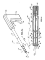
- Fig. 7 is a partial perspective view of a third embodiment expandable reamer according to the present invention.
-
- Corresponding reference characters indicate corresponding parts throughout the several views. Although the drawings represent embodiments of the present invention, the drawings are not necessarily to scale and certain features may be exaggerated in order to better illustrate and explain the present invention. The exemplification set out herein illustrates embodiments of the invention, in several forms, and such exemplifications are not to be construed as limiting the scope of the invention in any manner.
- The embodiments disclosed below are not intended to be exhaustive or limit the invention to the precise forms disclosed in the following detailed description. Rather, the embodiments are chosen and described so that others skilled in the art may utilize their teachings.
- First exemplary
expandable reamer 20, shown in Fig. 1, is formed from cannulatedshaft 22 havingbore 24 therethrough alonglongitudinal axis 26.Reamer 20 includesshank 28 andreamer body 30. Chuck end 32 for drivingreamer 20 is located atproximate end 34 ofshank 28.Reamer body 30 extending fromdistal end 36 ofshank 28 todistal end 38 ofreamer 20 includesdeformable cutting blades 40 andring 42.Blades 40 are coupled atproximate end 44 todistal end 36 ofshank 28.Blades 40 are also coupled at distal end 46 to ring 42. Advantageously, asring 42 is proximally drawn towardproximate end 32 ofreamer 20, at least a portion ofblades 40 extend radially outward fromlongitudinal axis 26, thereby increasing the cutting diameter ofreamer 20. -
Expandable reamer 20 is useful for cutting a chamber or cavity in a structure, the cavity having a greater diameter than the entry aperture into the structure and a greater diameter thanshaft 22. Referring to Fig. 6, for minimally invasive surgery, e.g., total hip arthroplasty,expandable reamer 120 may be inserted throughincision 50 defined insoft tissue 52 and throughaperture 60 and intobore 54 drilled inbone structure 56 offemur 58. Optionally, to further protectsoft tissue 52, a tubular retractor (not shown) may be inserted throughincision 50, withreamer 120 inserted through the tubular retractor to prevent contact ofsoft tissue 52 withblades 140. In one exemplary embodiment, the tubular retractor is coupled tobone structure 56 and further functions to guide insertion ofreamer 120. - After
blades 140 ofexpandable reamer 120 are located withbore 54,blades 140 may be extended to an expanded position while rotatingreamer 120, thereby forming cavity 62 inbone structure 56. For example, such aprocedure using reamer 120 may be used to removeneck 64 andhead 66 offemur 58. - Referring to Figs. 1 and 2, first exemplary
expandable reamer 20 includes sixblades 40 andring 42 which are formed from cannulatedshaft 22. In this exemplaryembodiment reamer body 30 has a hexagonal cross-section. The cross-section ofreamer body 30 may be a circle or a different numbered polygon with the number of sides determining the number of resultingblades 40. - Referring to the cross-sectional end view shown in Fig. 2,
blades 40 are formed by removingportion 70 which is coincident with one side of comer or apex 72 joining adjacent sides of the hexagon. Removingportions 70 createsslots 74 betweenadjacent blades 40.Slots 74 are milled inreamer body 30 so thatface 76 is directed radially towardlongitudinal axis 26. The wall ofslot 74opposite face 76 defines the trailing edge orheel 78 of the adjacently locatedblade 40. The remaining portion of the hexagonal side located between cuttingedge 72 andheel 78, referred to asland 80, forms the outer surface of eachblade 40.Inner surface 82 ofblades 40 defines bore 24 formed throughreamer body 30. - Because
slot 74 is located coincident to two adjoining sides of the hexagonal shape ofreamer body 30, cuttingedge 72 has a greater radius relative tolongitudinal axis 26 than any other point alongland 80. Thus,clearance angle 83, defined as the difference in radius between cuttingedge 72 and trailingedge 78, is provided so that cuttingedge 72 of eachblade 40 is the only portion ofblades 40 that will be in contact with the material being reamed. Firstexemplary reamer 20 shown in Fig. 2 is formed forcounterclockwise rotation 84, which rotates cuttingedge 72 and face 76 toward the surface to be reamed. - Referring now to Figs. 1 and 4, outward radial expansion of portions of
blades 40 is facilitated by deformation points 86. Eachblade 40 is divided intoproximal segment 88 anddistal segment 90.Segments blade 40 may be formed by interiorcircumferential relief 92 which is cut alonginterior surface 82 of eachblade 40 and which reduces the resistance ofblade 40 to bending or deforming outwardly. - Additionally,
proximal segment 88 of eachblade 40 is joined toshank 28. Deformation points 87 are formed by proximal exteriorcircumferential relief 94 cut inland 80 of eachblade 40. Similarly, deformation points 87 are located inblade 40 wheredistal segment 90 of eachblade 40 is connected todistal ring 42 ofreamer body 30. Deformation points 87 may be formed by distal exteriorcircumferential relief 96 cut in each land ofblade 40. Additionally, radially oriented arcuate notches 95 (Fig. 1) may be cut inblades 40 along cuttingedge 72 and coincident withreliefs blades 40 to bending to the expanded position. Although deformation points 86 and 87 are referred to as "points," deformation points 86 and 87 define lines or areas of deformation inblades 40. - Referring to Fig. 3B,
interior relief 92 andnotches 95 are provided betweensegments exterior reliefs notches 95 are provided at theproximal end 44 ofsegment 88 and distal end 46 ofsegment 90.Reliefs notches 95 facilitate folding or radially expanding the adjoining ends ofsegments interior relief 92 outwardly fromlongitudinal axis 26 and aboutproximate relief 94 anddistal relief 96. Alternatively, other types of deformation points as are known in the art may be utilized to hingably connectblade segments blades 40 may be substituted at the points of deformation, the material at the points of deformation may be thinned or otherwise made pliable, or a hinge or other type of relative motion device or member may be utilized. If a point of deformation comprises a thinned region, then the cross-sectional area at the point of deformation is smaller than the cross-sectional area of the portions of the blade adjacent the deformation point. - Referring to Fig.4,
mechanism 100 provides proximal translation ofring 42 towarddistal end 36 ofshank 28, thereby expandingblades 40 as described above.Mechanism 100 may comprise, for example,bushing 102, which may be rotatably coupled toring 42, andelongate member 104, for example, a rod.Elongate member 104 extends throughbore 24 inexpandable reamer 20 and is operable to translatering 42 alonglongitudinal axis 26.Exemplary driving device 106, shown in Figs. 3A and 4, may be utilized to rotationallydrive reamer 20 and to longitudinally translateelongate member 104. Drivingdevice 106 includeshandle 108,rotational drive 110 andtranslational drive 112; however, other devices or mechanisms capable of effecting rotational and translational motion may be utilized. - As shown in Fig. 4,
rotational drive 110 of drivingdevice 106 may be coupled withchuck end 32 andtranslational drive 112 may be coupled withelongate member 104. Referring to Fig. 3A,first actuator 114 functions to rotaterotational drive 110 and thusreamer 20 aboutlongitudinal axis 26.Second actuator 116 functions to translatetranslational drive 112 and thuselongate member 104 andbushing 102 alonglongitudinal axis 26. By actuatingsecond actuator 116 in a first direction, bushing 102 is drawn towarddistal end 36 ofshank 28, thereby deformingblades 42 radially outwardly to the expanded position shown in Fig. 3B. Actuatingsecond actuator 116 in a second direction distally advanceselongate member 104 andbushing 102 away fromdistal end 36 ofshank 28, thereby returningblades 40 to the contracted position, substantially parallel tolongitudinal axis 26 as shown in Fig. 3A. - Referring to Fig. 5, second exemplary
expandable reamer 120 includes cannulatedshaft 122 definingshank 128, Chuck end 132,reamer body 130,distal ring 142, and endcutter 144.End cutter 144 may be secured to ring 142 and may be used as an end mill to cut the bore which reamer 120 may then ream into a larger diameter cavity. -
Reamer body 130 includesblades 140 which are divided intomultiple blade segments deformation members 186 joining them may be designed to provide a specific desired shape and diameter ofreamer 120 when in the expanded position shown in Fig. 5. For example, an exemplary reamer may have two short segments coupled to opposite ends of a central long segment, thus providing a long cutting surface of uniform diameter between the distal and proximal ends of the blades. An exemplary reamer may alternatively have a single segment formed from pliable material which bows outwardly between the proximal and distal ends when compressed. - Referring to Fig. 6, advantageously,
expandable reamer 120 may be used to cut cavity 62 inbone structure 56 while maintaining minimally invasive surgical procedures. For example,incision 50 may be cut insoft tissue 52, a cylindrical sleeve (not shown) may be positioned throughincision 50 to holdopen incision 50 and protectsoft tissue 52 from damage byreamer 120, and then a drill or endcutter 144 ofexpandable reamer 120, may be used to formaperture 60 and bore 54 inbone structure 56 offemur 58. - In certain orthopedic procedures, it is necessary to cut large diameter cavity 62 in
bone structure 56, which may be, for example,femur 58. After bore 54 is formed inbone structure 56,reamer 120 may be inserted throughincision 50 andaperture 60 intobore 54. While driven rotationally,blades 140 are expanded so thatblades 140 ream bore 54 to an increased diameter, thus forming cavity 62. Cavity 62, having been formed byreamer 120 in an expanded position, has a larger diameter than the diameter ofaperature 60 andincision 50. After cavity 62 is reamed to the desired diameter,blades 140 ofreamer 120 may be contracted to their original diameter as described above, andreamer 120 removed throughaperture 60 andincision 50. Debris from removedbone structure 56 may then be flushed or otherwise removed from cavity 62 inhole 64. - The inventive reamer may also be used for other procedures requiring reaming and cutting. For example, for a minimally invasive total hip arthroplasty, rather than cutting cavity 62,
reamer 120 may be used, as above, to remove a complete portion ofbone structure 56, for example,neck 64 andhead 66 offemur 58. - Referring to Fig. 7, third exemplary
expandable reamer 220 includes cannulatedshaft 222,expandable blades 240, andexpansion member 250. In the third exemplary embodiment,blades 240 are coupled atproximate end 244 todistal end 236 of cannulatedshaft 222. Deformation points 286 are formed inblades 240 whereblades 240 are joined to cannulatedshaft 222. In a contracted position,blades 240 are substantially parallel to the longitudinal axis ofshaft 222, similar to the arrangement shown in Fig. 1 for firstexemplary reamer 20, andexpansion member 250 is positioned neardistal end 246 ofblades 240. -
Expansion member 250 has a larger diameter than the interior diameter between circumferentially locatedblades 240 adjacentproximate end 244; therefore, asexpansion member 250 is drawn proximally fromdistal end 246 toproximal end 244 ofblades 240, distal ends 246 extend radially outward about deformation points 286, as shown in Fig. 7. To contractblades 240 to their original position,expansion member 250 may be distally advanced to the original position neardistal end 246 ofblades 240, thus allowingblades 240 to return to the original positions substantially parallel toshaft 222. -
Blades 240 may return to the original position by the force applied by the structure being reamed asreamer 220 is withdrawn from the cavity formed. For example, asreamer 220 is withdrawn from the cavity,blades 240 may contact the structure walls forming the aperature leading into the cavity becauseblades 240 form a diameter betweenproximate end 244 anddistal end 246 that is greater than the diameter of the aperature. Thus,blades 240 will be deformed to the contracted position asreamer 240 is withdrawn from the cavity and through the aperature.Blades 240 may also be spring loaded or otherwise biased to their original contracted positions. Alternatively,reamer 220 may include engagement devices (not shown) coupled toexpansion member 250. The engagement devices drawblades 240 radially inward asmember 250 extends distally fromproximate end 244 towarddistal end 246 ofblades 240. - Referring again to Fig. 6, various combinations of the above-disclosed aspects of
exemplary reamers - In addition,
blades blades 40 may be normally biased to the expanded position as shown in Fig. 3A. However, application of a force againstblades 40 may deformblades 40 to the contracted position, as shown in Fig. 1, if the force is great enough to overcome, for example, spring loading, the material strength of deformation points 86, or another resistance to movement to the contract position. Such an arrangement may be used, for example, as a material-sensitive reamer used to remove softer cancellous bone while leaving generally intact the harder cortical bone.Blades - While this invention has been described as having an exemplary design, the present invention may be further modified within the spirit and scope of this disclosure. This application is therefore intended to cover any variations, uses, or adaptations of the invention using its general principles. Further, this application is intended to cover such departures from the present disclosure as come within known or customary practice in the art to which this invention pertains.
Claims (31)
- A reamer comprising:a shank;a reamer body having a longitudinal axis; anda blade formed in said reamer body, said blade deformable between a contracted position and an expanded position.
- The reamer of claim 1, wherein said shank has a radius measured from said longitudinal axis, said blade in said contracted position extending no further from said longitudinal axis than said radius of said shank.
- The reamer of claim 1, wherein said shank has a radius measured from said longitudinal axis, said blade in said expanded position extending further from said longitudinal axis than said radius of said shank.
- The reamer of claim 1, wherein said blade in said contracted position is substantially parallel to said longitudinal axis.
- The reamer of claim 1, wherein said blade in said expanded position comprises a portion oriented radially outward from said longitudinal axis.
- The reamer of claim 1, wherein said blade comprises at least one deformation point.
- The reamer of claim 6, wherein said at least one deformation point comprises an exterior circumferential relief.
- The reamer of claim 7, wherein said exterior circumferential relief is formed in a proximate end of said blade, said reamer further comprises a ring coupled to a distal end of said blade, and said at least one deformation point further comprises an exterior circumferential relief formed in said distal end of said blade.
- The reamer of claim 6, wherein said at least one deformation point comprises at least one interior circumferential relief formed in said blade between said proximate end and said distal end.
- The reamer of claim 6, wherein said at least one deformation point comprises a radially oriented cut in said blade.
- The reamer of claim 6, wherein said at least one deformation point comprises a thinned region.
- The reamer of claim 1, wherein said reamer body comprises a shaft having a polygonal cross-section, an edge of said blade being coincident with an apex formed by two adjacent sides of said polygonal reamer body.
- The reamer of claim 1, further comprising an actuating means for moving said blade between said contracted position and said expanded position.
- The reamer of claim 13, wherein said shank is cannulated and said actuating means comprises an elongate member connected to said blade, proximate translation of said elongate member moving said blade from said contracted position to said expanded position, and distal translation of said elongate member moving said blade from said expanded position to said contracted position.
- The reamer of claim 1, further comprising an end cutter secured to a distal end of said reamer body.
- The reamer of claim 1, wherein said blade is biased to said expanded position and is collapsible to said contracted position upon application of a radially inward force upon said blade.
- A reamer, comprising:a shank;a reamer body having a longitudinal axis;a blade formed in said reamer body; anddeformation means for deforming said blade between a contracted position and an expanded position.
- The reamer of claim 17, wherein said shank has a radius measured from said longitudinal axis, said blade in said contracted position extending no further from said longitudinal axis than said radius of said shank.
- The reamer of claim 17, wherein said shank has a radius measured from said longitudinal axis, said blade in said expanded position extending further from said longitudinal axis than said radius of said shank.
- The reamer of claim 17, wherein said blade in said contracted position is substantially parallel to said longitudinal axis.
- The reamer of claim 17, wherein said blade in said expanded position comprises a portion oriented radially outward from said longitudinal axis.
- The reamer of claim 17, wherein said reamer body comprises a shaft having a polygonal cross-section, an edge of said blade being coincident with an apex formed by two adjacent sides of said polygonal reamer body.
- The reamer of claim 17, further comprising an actuating means for moving said blade between said contracted position and said expanded position.
- The reamer of claim 23, wherein said shank is cannulated and said actuating means comprises an elongate member connected to said blade, proximate translation of said elongate member moving said blade from said contracted position to said expanded position, and distal translation of said elongated member moving said blade from said expanded position to said contracted position.
- The reamer of claim 17, further comprising an end cutter secured to a distal end of said reamer body.
- The reamer of claim 17, wherein said blade is biased to said expanded position and is collapsible to said contracted position upon application of a radially inward force upon said blade.
- A reamer, comprising:a cannulated shaft having a wall, a proximate end and a distal end, said cannulated shaft defining a longitudinal axis, said wall having a plurality of slots therethrough, said plurality of slots extending from said distal end toward said proximate end; anda plurality of blades, each one of said plurality of blades defined by said wall between adjacent ones of said plurality of slots.
- The reamer of claim 27, wherein each one of said plurality of blades includes at least one segment, adjacent said segments being arranged lengthwise along each one of said plurality of blades.
- The reamer of claim 28, further comprising:a plurality of deformation points coupling adjacent said segments and coupling each one of said plurality of blades to said cannulated shaft;said plurality of blades deformable between a contracted position and an expanded position;said plurality of blades being substantially parallel to said longitudinal axis in said contracted position; andsaid plurality of blades being deformable at said deformation points to achieve said expanded position.
- The reamer of claim 29, wherein a portion of said wall of said shaft in which said plurality of blades are formed has a polygonal cross-section.
- The reamer of claim 27, further comprising an end cutter secured to a distal end of said plurality of blades.
Applications Claiming Priority (2)
| Application Number | Priority Date | Filing Date | Title |
|---|---|---|---|
| US10/721,808 US20050113836A1 (en) | 2003-11-25 | 2003-11-25 | Expandable reamer |
| US721808 | 2003-11-25 |
Publications (2)
| Publication Number | Publication Date |
|---|---|
| EP1535579A2 true EP1535579A2 (en) | 2005-06-01 |
| EP1535579A3 EP1535579A3 (en) | 2005-06-15 |
Family
ID=34465674
Family Applications (1)
| Application Number | Title | Priority Date | Filing Date |
|---|---|---|---|
| EP04257314A Withdrawn EP1535579A3 (en) | 2003-11-25 | 2004-11-25 | Expandable reamer |
Country Status (5)
| Country | Link |
|---|---|
| US (1) | US20050113836A1 (en) |
| EP (1) | EP1535579A3 (en) |
| JP (1) | JP2005152650A (en) |
| AU (1) | AU2004233454A1 (en) |
| CA (1) | CA2488225A1 (en) |
Cited By (17)
| Publication number | Priority date | Publication date | Assignee | Title |
|---|---|---|---|---|
| WO2007003243A1 (en) * | 2005-07-05 | 2007-01-11 | Plus Orthopedics Ag | Bone cutter |
| WO2009143496A1 (en) * | 2008-05-22 | 2009-11-26 | Trinity Orthopedics, Llc | Devices and methods for spinal reduction, displacement and resection |
| US8287538B2 (en) | 2008-01-14 | 2012-10-16 | Conventus Orthopaedics, Inc. | Apparatus and methods for fracture repair |
| WO2013101835A1 (en) * | 2011-12-27 | 2013-07-04 | Symmetry Medical, Inc. | Expandable retrograde drill |
| WO2014174521A1 (en) * | 2013-04-24 | 2014-10-30 | T.A.G. Medical Devices - Agriculture Cooperative Ltd. | Bone material removal devices |
| US8906022B2 (en) | 2010-03-08 | 2014-12-09 | Conventus Orthopaedics, Inc. | Apparatus and methods for securing a bone implant |
| US8961518B2 (en) | 2010-01-20 | 2015-02-24 | Conventus Orthopaedics, Inc. | Apparatus and methods for bone access and cavity preparation |
| EP2928390A4 (en) * | 2012-12-10 | 2017-04-12 | The Curators of the University of Missouri | System, apparatus, and method for grafting tissue |
| US9730739B2 (en) | 2010-01-15 | 2017-08-15 | Conventus Orthopaedics, Inc. | Rotary-rigid orthopaedic rod |
| US9980715B2 (en) | 2014-02-05 | 2018-05-29 | Trinity Orthopedics, Llc | Anchor devices and methods of use |
| US10022132B2 (en) | 2013-12-12 | 2018-07-17 | Conventus Orthopaedics, Inc. | Tissue displacement tools and methods |
| US10448959B2 (en) | 2015-04-09 | 2019-10-22 | T.A.G. Medical Devices—Agriculture Cooperative Ltd. | Bone material removal device and a method for use thereof |
| US10537340B2 (en) | 2014-10-19 | 2020-01-21 | T.A.G. Medical Devices—Agriculture Cooperative Ltd. | Kit including a guiding system and a bone material removal device |
| US10660657B2 (en) | 2016-02-11 | 2020-05-26 | T.A.G. Medical Devices—Agriculture Cooperative Ltd. | Bone material removal device and a method for use thereof |
| US10918426B2 (en) | 2017-07-04 | 2021-02-16 | Conventus Orthopaedics, Inc. | Apparatus and methods for treatment of a bone |
| US11020132B2 (en) | 2016-04-24 | 2021-06-01 | T.A.G. Medical Devices—Agriculture Cooperative Ltd. | Guiding device and method of using thereof |
| US11202641B2 (en) | 2018-08-01 | 2021-12-21 | T.A.G. Medical Devices—Agriculture Cooperative Ltd. | Adjustable drilling device and a method for use thereof |
Families Citing this family (101)
| Publication number | Priority date | Publication date | Assignee | Title |
|---|---|---|---|---|
| US7632274B2 (en) * | 2000-02-16 | 2009-12-15 | Trans1 Inc. | Thin cutter blades with retaining film for preparing intervertebral disc spaces |
| US7500977B2 (en) | 2003-10-23 | 2009-03-10 | Trans1 Inc. | Method and apparatus for manipulating material in the spine |
| US7488329B2 (en) * | 2000-03-07 | 2009-02-10 | Zimmer Technology, Inc. | Method and apparatus for reducing femoral fractures |
| US7485119B2 (en) * | 2000-03-07 | 2009-02-03 | Zimmer Technology, Inc. | Method and apparatus for reducing femoral fractures |
| US20030220646A1 (en) * | 2002-05-23 | 2003-11-27 | Thelen Sarah L. | Method and apparatus for reducing femoral fractures |
| US20060052788A1 (en) * | 2003-02-04 | 2006-03-09 | Thelen Sarah L | Expandable fixation devices for minimally invasive surgery |
| US7507241B2 (en) * | 2004-04-05 | 2009-03-24 | Expanding Orthopedics Inc. | Expandable bone device |
| US20090088846A1 (en) | 2007-04-17 | 2009-04-02 | David Myung | Hydrogel arthroplasty device |
| US7479144B2 (en) * | 2004-12-10 | 2009-01-20 | Symmetry Medical, Inc. | Collapsible orthopaedic reamer |
| US20060178594A1 (en) * | 2005-02-07 | 2006-08-10 | Neubardt Seth L | Apparatus and method for locating defects in bone tissue |
| US20060229624A1 (en) * | 2005-03-31 | 2006-10-12 | Zimmer Technology, Inc. | Orthopaedic cutting instrument and method |
| US20070067034A1 (en) * | 2005-08-31 | 2007-03-22 | Chirico Paul E | Implantable devices and methods for treating micro-architecture deterioration of bone tissue |
| US8998923B2 (en) * | 2005-08-31 | 2015-04-07 | Spinealign Medical, Inc. | Threaded bone filling material plunger |
| EP1948064A4 (en) * | 2005-11-10 | 2013-03-06 | Zimmer Inc | Minamally invasive orthopaedic delivery devices and tools |
| US20070276396A1 (en) * | 2006-05-10 | 2007-11-29 | Howmedica Osteonics Corp. | Modular acetabular reamer |
| US8480673B2 (en) * | 2006-06-01 | 2013-07-09 | Osteo Innovations Llc | Cavity creation device and methods of use |
| US20100217335A1 (en) * | 2008-12-31 | 2010-08-26 | Chirico Paul E | Self-expanding bone stabilization devices |
| US20080097469A1 (en) * | 2006-10-18 | 2008-04-24 | Gruber William H | Intrauterine access and procedure system with laterally deflectable sheath |
| US20080146872A1 (en) * | 2006-11-07 | 2008-06-19 | Gruber William H | Mechanical distension systems for performing a medical procedure in a remote space |
| US8025656B2 (en) | 2006-11-07 | 2011-09-27 | Hologic, Inc. | Methods, systems and devices for performing gynecological procedures |
| US8449545B2 (en) * | 2007-02-09 | 2013-05-28 | Christopher G. Sidebotham | Low cost modular tapered hollow reamer for medical applications |
| US8556897B2 (en) | 2007-02-09 | 2013-10-15 | Christopher G. Sidebotham | Modular spherical hollow reamer assembly for medical applications |
| US8535316B2 (en) * | 2007-02-09 | 2013-09-17 | Randall J. Lewis | Hollow reamer for medical applications |
| US8357163B2 (en) | 2007-02-09 | 2013-01-22 | Sidebotham Christopher G | Low cost modular tapered and spherical hollow reamers for medical applications |
| US8523866B2 (en) | 2007-02-09 | 2013-09-03 | Christopher G. Sidebotham | Modular tapered hollow reamer for medical applications |
| US8403931B2 (en) * | 2007-02-09 | 2013-03-26 | Christopher G. Sidebotham | Modular tapered hollow reamer for medical applications |
| EP2131769B1 (en) * | 2007-03-02 | 2011-04-27 | Spinealign Medical, Inc. | Fracture fixation system |
| US9259233B2 (en) | 2007-04-06 | 2016-02-16 | Hologic, Inc. | Method and device for distending a gynecological cavity |
| US20090270898A1 (en) | 2007-04-06 | 2009-10-29 | Interlace Medical, Inc. | Tissue removal device with high reciprocation rate |
| EP2134283B1 (en) | 2007-04-06 | 2014-06-11 | Hologic, Inc. | System and device for tissue removal |
| US9095366B2 (en) | 2007-04-06 | 2015-08-04 | Hologic, Inc. | Tissue cutter with differential hardness |
| US20080275448A1 (en) | 2007-05-02 | 2008-11-06 | Sackett Samuel G | Expandable proximal reamer |
| US7935117B2 (en) * | 2007-05-02 | 2011-05-03 | Depuy Products, Inc. | Expandable proximal reamer |
| US20090276048A1 (en) * | 2007-05-08 | 2009-11-05 | Chirico Paul E | Devices and method for bilateral support of a compression-fractured vertebral body |
| US8038679B2 (en) * | 2007-05-23 | 2011-10-18 | Stryker Trauma Gmbh | Reaming device |
| US20090131867A1 (en) | 2007-11-16 | 2009-05-21 | Liu Y King | Steerable vertebroplasty system with cavity creation element |
| US20090131886A1 (en) | 2007-11-16 | 2009-05-21 | Liu Y King | Steerable vertebroplasty system |
| US9510885B2 (en) | 2007-11-16 | 2016-12-06 | Osseon Llc | Steerable and curvable cavity creation system |
| US20090177206A1 (en) * | 2008-01-08 | 2009-07-09 | Zimmer Spine, Inc. | Instruments, implants, and methods for fixation of vertebral compression fractures |
| US20090216260A1 (en) * | 2008-02-20 | 2009-08-27 | Souza Alison M | Interlocking handle |
| CA2718718A1 (en) * | 2008-03-21 | 2009-09-24 | Biomimedica, Inc | Methods, devices and compositions for adhering hydrated polymer implants to bone |
| EP2297217B1 (en) * | 2008-07-07 | 2021-10-20 | Hyalex Orthopaedics, Inc. | Hydrophilic interpenetrating polymer networks derived from hydrophobic polymers |
| US8883915B2 (en) | 2008-07-07 | 2014-11-11 | Biomimedica, Inc. | Hydrophobic and hydrophilic interpenetrating polymer networks derived from hydrophobic polymers and methods of preparing the same |
| US20120209396A1 (en) | 2008-07-07 | 2012-08-16 | David Myung | Orthopedic implants having gradient polymer alloys |
| US20100168748A1 (en) * | 2008-07-16 | 2010-07-01 | Knopp Peter G | Morselizer |
| WO2010017282A1 (en) * | 2008-08-05 | 2010-02-11 | Biomimedica, Inc. | Polyurethane-grafted hydrogels |
| US8246627B2 (en) * | 2008-08-07 | 2012-08-21 | Stryker Corporation | Cement delivery device for introducing cement into tissue, the device having a cavity creator |
| US11903602B2 (en) | 2009-04-29 | 2024-02-20 | Hologic, Inc. | Uterine fibroid tissue removal device |
| US20100298832A1 (en) | 2009-05-20 | 2010-11-25 | Osseon Therapeutics, Inc. | Steerable curvable vertebroplasty drill |
| CN102469999B (en) * | 2009-07-24 | 2016-03-09 | 史密夫和内修有限公司 | For cutting out the operating theater instruments of cavity in intermedullary canal |
| EP2512354A4 (en) * | 2009-12-18 | 2015-09-09 | Biomimedica Inc | Method, device, and system for shaving and shaping of a joint |
| US8696672B2 (en) * | 2010-01-22 | 2014-04-15 | Baxano Surgical, Inc. | Abrading tool for preparing intervertebral disc spaces |
| JP4597260B1 (en) * | 2010-03-30 | 2010-12-15 | 宏 黒澤 | Jig for forming implant cavity and surgical tool |
| WO2011137377A1 (en) | 2010-04-29 | 2011-11-03 | Dfine, Inc. | System for use in treatment of vertebral fractures |
| US9724140B2 (en) | 2010-06-02 | 2017-08-08 | Wright Medical Technology, Inc. | Tapered, cylindrical cruciform hammer toe implant and method |
| US9498273B2 (en) | 2010-06-02 | 2016-11-22 | Wright Medical Technology, Inc. | Orthopedic implant kit |
| US8608785B2 (en) | 2010-06-02 | 2013-12-17 | Wright Medical Technology, Inc. | Hammer toe implant with expansion portion for retrograde approach |
| US9028496B2 (en) * | 2011-04-12 | 2015-05-12 | William L. Tontz | Device for establishing supportive forces in the bony structure of a skeleton |
| CA2833543A1 (en) | 2011-05-05 | 2012-11-08 | Zyga Technology, Inc. | Sacroiliac fusion system |
| US20130103157A1 (en) | 2011-10-03 | 2013-04-25 | Lampros Kourtis | Polymeric adhesive for anchoring compliant materials to another surface |
| EP2782524B1 (en) | 2011-11-21 | 2017-12-20 | Biomimedica, Inc | Systems for anchoring orthopaedic implants to bone |
| WO2013164830A1 (en) * | 2012-05-03 | 2013-11-07 | Ultimate Joint Ltd. | In-situ formation of a joint replacement prosthesis |
| US10350072B2 (en) * | 2012-05-24 | 2019-07-16 | Cartiva, Inc. | Tooling for creating tapered opening in tissue and related methods |
| US9629646B2 (en) | 2012-07-11 | 2017-04-25 | Jens Kather | Curved burr surgical instrument |
| US9011443B2 (en) | 2012-09-20 | 2015-04-21 | Depuy Mitek, Llc | Low profile reamers and methods of use |
| US10357259B2 (en) | 2012-12-05 | 2019-07-23 | Smith & Nephew, Inc. | Surgical instrument |
| WO2014089198A1 (en) * | 2012-12-05 | 2014-06-12 | Smith & Nephew, Inc. | Surgical instrument |
| US8945232B2 (en) | 2012-12-31 | 2015-02-03 | Wright Medical Technology, Inc. | Ball and socket implants for correction of hammer toes and claw toes |
| US9084615B2 (en) | 2013-01-31 | 2015-07-21 | Depuy Mitek, Llc | Methods and devices for removing abnormalities from bone |
| MX2015011809A (en) | 2013-03-12 | 2016-04-19 | Smith & Nephew Inc | Retro guidewire reamer. |
| US9913728B2 (en) | 2013-03-14 | 2018-03-13 | Quandary Medical, Llc | Spinal implants and implantation system |
| US9724139B2 (en) | 2013-10-01 | 2017-08-08 | Wright Medical Technology, Inc. | Hammer toe implant and method |
| EP3057517B1 (en) | 2013-10-15 | 2020-04-08 | Stryker Corporation | Device for creating a void space in a living tissue, the device including a handle with a control knob that can be set regardless of the orientation of the handle |
| US9474561B2 (en) | 2013-11-19 | 2016-10-25 | Wright Medical Technology, Inc. | Two-wire technique for installing hammertoe implant |
| US11219466B2 (en) * | 2018-06-06 | 2022-01-11 | Acumed Llc | Orthopedic reamer with expandable cutting head |
| US9861375B2 (en) | 2014-01-09 | 2018-01-09 | Zyga Technology, Inc. | Undercutting system for use in conjunction with sacroiliac fusion |
| US9498266B2 (en) | 2014-02-12 | 2016-11-22 | Wright Medical Technology, Inc. | Intramedullary implant, system, and method for inserting an implant into a bone |
| US9545274B2 (en) | 2014-02-12 | 2017-01-17 | Wright Medical Technology, Inc. | Intramedullary implant, system, and method for inserting an implant into a bone |
| US9517076B2 (en) | 2014-03-11 | 2016-12-13 | Lenkbar, Llc | Reaming instrument with adjustable profile |
| US9603607B2 (en) | 2014-03-11 | 2017-03-28 | Lenkbar, Llc | Reaming instrument with adjustable profile |
| US9243881B2 (en) | 2014-05-29 | 2016-01-26 | Smith & Nephew, Inc. | Retrograde reamer depth tub gage |
| US9956015B2 (en) | 2014-07-03 | 2018-05-01 | Acumed Llc | Bone plate with movable joint |
| US20160045207A1 (en) * | 2014-08-14 | 2016-02-18 | Biomet Manufacturing, Llc | Flexible bone reamer |
| WO2016043751A1 (en) | 2014-09-18 | 2016-03-24 | Wright Medical Technology, Inc. | Hammertoe implant and instrument |
| WO2016053834A1 (en) | 2014-10-01 | 2016-04-07 | Smith & Nephew, Inc. | Bone marrow lesion drill |
| CN105960211B (en) | 2014-12-19 | 2019-01-11 | 瑞特医疗技术公司 | For anchor log in the marrow of interphalangeal arthrodesis of toe |
| US10080571B2 (en) | 2015-03-06 | 2018-09-25 | Warsaw Orthopedic, Inc. | Surgical instrument and method |
| US11077228B2 (en) | 2015-08-10 | 2021-08-03 | Hyalex Orthopaedics, Inc. | Interpenetrating polymer networks |
| US10743912B2 (en) | 2015-11-17 | 2020-08-18 | Lenkbar, Llc | Surgical tunneling instrument with expandable section |
| US10492800B2 (en) | 2015-11-25 | 2019-12-03 | Lenkbar, Llc | Bone cutting instrument with expandable section |
| CN107874805A (en) * | 2016-09-29 | 2018-04-06 | 张国伟 | A kind of reamer |
| CN109862834B (en) | 2016-10-27 | 2022-05-24 | Dfine有限公司 | Bendable osteotome with cement delivery channel |
| US9737313B1 (en) | 2016-11-07 | 2017-08-22 | Roger C. Sohn | Shoulder reamer devices, systems including the same, and related methods |
| US11026744B2 (en) | 2016-11-28 | 2021-06-08 | Dfine, Inc. | Tumor ablation devices and related methods |
| EP3551100B1 (en) | 2016-12-09 | 2021-11-10 | Dfine, Inc. | Medical devices for treating hard tissues |
| EP3565486B1 (en) | 2017-01-06 | 2021-11-10 | Dfine, Inc. | Osteotome with a distal portion for simultaneous advancement and articulation |
| US10456145B2 (en) | 2017-05-16 | 2019-10-29 | Arthrex, Inc. | Expandable reamers |
| US10869950B2 (en) | 2018-07-17 | 2020-12-22 | Hyalex Orthopaedics, Inc. | Ionic polymer compositions |
| WO2020097339A1 (en) | 2018-11-08 | 2020-05-14 | Dfine, Inc. | Tumor ablation device and related systems and methods |
| WO2020219392A2 (en) | 2019-04-24 | 2020-10-29 | Stryker Corporation | Systems and methods for off-axis augmentation of a vertebral body |
| US20230404551A1 (en) * | 2020-11-18 | 2023-12-21 | University Of Washington | Deployable Tubular Biopsy Device |
Citations (3)
| Publication number | Priority date | Publication date | Assignee | Title |
|---|---|---|---|---|
| DE3840466A1 (en) * | 1988-12-01 | 1990-06-07 | Lieke Michael | Special cutters for use in implant technology |
| WO2001060262A1 (en) * | 2000-02-16 | 2001-08-23 | Axiamed, Inc. | Apparatus for forming shaped axial bores through spinal vertebrae |
| US20020183758A1 (en) * | 2001-06-01 | 2002-12-05 | Middleton Lance M. | Tissue cavitation device and method |
Family Cites Families (11)
| Publication number | Priority date | Publication date | Assignee | Title |
|---|---|---|---|---|
| US2450223A (en) * | 1944-11-25 | 1948-09-28 | William R Barbour | Well reaming apparatus |
| US3702611A (en) * | 1971-06-23 | 1972-11-14 | Meyer Fishbein | Surgical expansive reamer for hip socket |
| US5620450A (en) * | 1992-09-30 | 1997-04-15 | Staar Surgical Company, Inc. | Transverse hinged deformable intraocular lens injecting apparatus |
| US5885258A (en) * | 1996-02-23 | 1999-03-23 | Memory Medical Systems, Inc. | Medical instrument with slotted memory metal tube |
| US6070677A (en) * | 1997-12-02 | 2000-06-06 | I.D.A. Corporation | Method and apparatus for enhancing production from a wellbore hole |
| US6632197B2 (en) * | 1999-04-16 | 2003-10-14 | Thomas R. Lyon | Clear view cannula |
| US6383188B2 (en) * | 2000-02-15 | 2002-05-07 | The Spineology Group Llc | Expandable reamer |
| US20010031981A1 (en) * | 2000-03-31 | 2001-10-18 | Evans Michael A. | Method and device for locating guidewire and treating chronic total occlusions |
| US6676665B2 (en) * | 2000-08-11 | 2004-01-13 | Sdgi Holdings, Inc. | Surgical instrumentation and method for treatment of the spine |
| US6814734B2 (en) * | 2001-06-18 | 2004-11-09 | Sdgi Holdings, Inc, | Surgical instrumentation and method for forming a passage in bone having an enlarged cross-sectional portion |
| US6976547B2 (en) * | 2002-07-16 | 2005-12-20 | Cdx Gas, Llc | Actuator underreamer |
-
2003
- 2003-11-25 US US10/721,808 patent/US20050113836A1/en not_active Abandoned
-
2004
- 2004-11-23 CA CA002488225A patent/CA2488225A1/en not_active Abandoned
- 2004-11-24 AU AU2004233454A patent/AU2004233454A1/en not_active Abandoned
- 2004-11-25 JP JP2004340692A patent/JP2005152650A/en active Pending
- 2004-11-25 EP EP04257314A patent/EP1535579A3/en not_active Withdrawn
Patent Citations (3)
| Publication number | Priority date | Publication date | Assignee | Title |
|---|---|---|---|---|
| DE3840466A1 (en) * | 1988-12-01 | 1990-06-07 | Lieke Michael | Special cutters for use in implant technology |
| WO2001060262A1 (en) * | 2000-02-16 | 2001-08-23 | Axiamed, Inc. | Apparatus for forming shaped axial bores through spinal vertebrae |
| US20020183758A1 (en) * | 2001-06-01 | 2002-12-05 | Middleton Lance M. | Tissue cavitation device and method |
Cited By (33)
| Publication number | Priority date | Publication date | Assignee | Title |
|---|---|---|---|---|
| WO2007003243A1 (en) * | 2005-07-05 | 2007-01-11 | Plus Orthopedics Ag | Bone cutter |
| US8287538B2 (en) | 2008-01-14 | 2012-10-16 | Conventus Orthopaedics, Inc. | Apparatus and methods for fracture repair |
| US11399878B2 (en) | 2008-01-14 | 2022-08-02 | Conventus Orthopaedics, Inc. | Apparatus and methods for fracture repair |
| US10603087B2 (en) | 2008-01-14 | 2020-03-31 | Conventus Orthopaedics, Inc. | Apparatus and methods for fracture repair |
| US9517093B2 (en) | 2008-01-14 | 2016-12-13 | Conventus Orthopaedics, Inc. | Apparatus and methods for fracture repair |
| US9788870B2 (en) | 2008-01-14 | 2017-10-17 | Conventus Orthopaedics, Inc. | Apparatus and methods for fracture repair |
| WO2009143496A1 (en) * | 2008-05-22 | 2009-11-26 | Trinity Orthopedics, Llc | Devices and methods for spinal reduction, displacement and resection |
| US9730739B2 (en) | 2010-01-15 | 2017-08-15 | Conventus Orthopaedics, Inc. | Rotary-rigid orthopaedic rod |
| US8961518B2 (en) | 2010-01-20 | 2015-02-24 | Conventus Orthopaedics, Inc. | Apparatus and methods for bone access and cavity preparation |
| EP2523616A4 (en) * | 2010-01-20 | 2015-09-30 | Conventus Orthopaedics Inc | Apparatus and methods for bone access and cavity preparation |
| AU2011207550B2 (en) * | 2010-01-20 | 2016-03-10 | Conventus Orthopaedics, Inc. | Apparatus and methods for bone access and cavity preparation |
| US9848889B2 (en) | 2010-01-20 | 2017-12-26 | Conventus Orthopaedics, Inc. | Apparatus and methods for bone access and cavity preparation |
| US9993277B2 (en) | 2010-03-08 | 2018-06-12 | Conventus Orthopaedics, Inc. | Apparatus and methods for securing a bone implant |
| US8906022B2 (en) | 2010-03-08 | 2014-12-09 | Conventus Orthopaedics, Inc. | Apparatus and methods for securing a bone implant |
| WO2013101835A1 (en) * | 2011-12-27 | 2013-07-04 | Symmetry Medical, Inc. | Expandable retrograde drill |
| EP2928390A4 (en) * | 2012-12-10 | 2017-04-12 | The Curators of the University of Missouri | System, apparatus, and method for grafting tissue |
| US10188403B2 (en) | 2013-04-24 | 2019-01-29 | T.A.G. Medical Devices—Agriculture Cooperative Ltd. | Bone material removal devices |
| WO2014174521A1 (en) * | 2013-04-24 | 2014-10-30 | T.A.G. Medical Devices - Agriculture Cooperative Ltd. | Bone material removal devices |
| US9668750B2 (en) | 2013-04-24 | 2017-06-06 | T.A.G. Medical Devices—Agriculture Cooperative Ltd. | Bone material removal devices |
| US10076342B2 (en) | 2013-12-12 | 2018-09-18 | Conventus Orthopaedics, Inc. | Tissue displacement tools and methods |
| US10022132B2 (en) | 2013-12-12 | 2018-07-17 | Conventus Orthopaedics, Inc. | Tissue displacement tools and methods |
| US9980715B2 (en) | 2014-02-05 | 2018-05-29 | Trinity Orthopedics, Llc | Anchor devices and methods of use |
| US10537340B2 (en) | 2014-10-19 | 2020-01-21 | T.A.G. Medical Devices—Agriculture Cooperative Ltd. | Kit including a guiding system and a bone material removal device |
| US11896242B2 (en) | 2014-10-19 | 2024-02-13 | T.A.G. Medical Products Corporation Ltd. | Kit including a guiding system and a bone material removal device |
| US11033283B2 (en) | 2014-10-19 | 2021-06-15 | T.A.G. Medical Devices—Agriculture Cooperative Ltd. | Kit including a guiding system and a bone material removal device |
| US10448959B2 (en) | 2015-04-09 | 2019-10-22 | T.A.G. Medical Devices—Agriculture Cooperative Ltd. | Bone material removal device and a method for use thereof |
| US11779353B2 (en) | 2015-04-09 | 2023-10-10 | T.A.G. Medical Products Corporation Ltd. | Bone material removal device and a method for use thereof |
| US10660657B2 (en) | 2016-02-11 | 2020-05-26 | T.A.G. Medical Devices—Agriculture Cooperative Ltd. | Bone material removal device and a method for use thereof |
| US11446042B2 (en) | 2016-02-11 | 2022-09-20 | T.A.G. Medical Products Corporation Ltd. | Bone material removal device and a method for use thereof |
| US11020132B2 (en) | 2016-04-24 | 2021-06-01 | T.A.G. Medical Devices—Agriculture Cooperative Ltd. | Guiding device and method of using thereof |
| US10918426B2 (en) | 2017-07-04 | 2021-02-16 | Conventus Orthopaedics, Inc. | Apparatus and methods for treatment of a bone |
| US11202641B2 (en) | 2018-08-01 | 2021-12-21 | T.A.G. Medical Devices—Agriculture Cooperative Ltd. | Adjustable drilling device and a method for use thereof |
| US11690635B2 (en) | 2018-08-01 | 2023-07-04 | T.A.G. Medical Products Corporation Ltd. | Adjustable drilling device and a method for use thereof |
Also Published As
| Publication number | Publication date |
|---|---|
| JP2005152650A (en) | 2005-06-16 |
| AU2004233454A1 (en) | 2005-06-09 |
| US20050113836A1 (en) | 2005-05-26 |
| EP1535579A3 (en) | 2005-06-15 |
| CA2488225A1 (en) | 2005-05-25 |
Similar Documents
| Publication | Publication Date | Title |
|---|---|---|
| EP1535579A2 (en) | Expandable reamer | |
| EP2774556B1 (en) | Expandable reamer | |
| US8926615B2 (en) | System and method for retrograde procedure | |
| US7217271B2 (en) | Orthopaedic reamer driver for minimally invasive surgery | |
| US8740907B2 (en) | Apparatus for and method of providing a hip replacement | |
| US20040111092A1 (en) | Apparatus for and method of providing a hip replacement | |
| JP7210688B2 (en) | surgical rotary cutting tool | |
| US20230000499A1 (en) | A unit for the reaming of the surface of joint cartilage and of periarticular bone of an acetabulum and femoral head | |
| WO2013179002A1 (en) | A trial instrument for use in orthopaedic surgery |
Legal Events
| Date | Code | Title | Description |
|---|---|---|---|
| PUAI | Public reference made under article 153(3) epc to a published international application that has entered the european phase |
Free format text: ORIGINAL CODE: 0009012 |
|
| PUAL | Search report despatched |
Free format text: ORIGINAL CODE: 0009013 |
|
| AK | Designated contracting states |
Kind code of ref document: A2 Designated state(s): AT BE BG CH CY CZ DE DK EE ES FI FR GB GR HU IE IS IT LI LU MC NL PL PT RO SE SI SK TR |
|
| AX | Request for extension of the european patent |
Extension state: AL HR LT LV MK YU |
|
| AK | Designated contracting states |
Kind code of ref document: A3 Designated state(s): AT BE BG CH CY CZ DE DK EE ES FI FR GB GR HU IE IS IT LI LU MC NL PL PT RO SE SI SK TR |
|
| AX | Request for extension of the european patent |
Extension state: AL HR LT LV MK YU |
|
| 17P | Request for examination filed |
Effective date: 20051109 |
|
| AKX | Designation fees paid |
Designated state(s): AT BE BG CH CY CZ DE DK EE ES FI FR GB GR HU IE IS IT LI LU MC NL PL PT RO SE SI SK TR |
|
| 17Q | First examination report despatched |
Effective date: 20070904 |
|
| STAA | Information on the status of an ep patent application or granted ep patent |
Free format text: STATUS: THE APPLICATION IS DEEMED TO BE WITHDRAWN |
|
| 18D | Application deemed to be withdrawn |
Effective date: 20080115 |