EP1457550A2 - Composition for removing residues from the microstructure of an object - Google Patents
Composition for removing residues from the microstructure of an object Download PDFInfo
- Publication number
- EP1457550A2 EP1457550A2 EP04011792A EP04011792A EP1457550A2 EP 1457550 A2 EP1457550 A2 EP 1457550A2 EP 04011792 A EP04011792 A EP 04011792A EP 04011792 A EP04011792 A EP 04011792A EP 1457550 A2 EP1457550 A2 EP 1457550A2
- Authority
- EP
- European Patent Office
- Prior art keywords
- composition according
- additive
- solvent
- fluoride
- residues
- Prior art date
- Legal status (The legal status is an assumption and is not a legal conclusion. Google has not performed a legal analysis and makes no representation as to the accuracy of the status listed.)
- Granted
Links
- 239000000203 mixture Substances 0.000 title claims abstract description 29
- 239000000654 additive Substances 0.000 claims abstract description 66
- 230000000996 additive effect Effects 0.000 claims abstract description 56
- 239000006184 cosolvent Substances 0.000 claims abstract description 37
- KRHYYFGTRYWZRS-UHFFFAOYSA-M Fluoride anion Chemical compound [F-] KRHYYFGTRYWZRS-UHFFFAOYSA-M 0.000 claims abstract description 18
- 125000000217 alkyl group Chemical group 0.000 claims abstract description 8
- 229910052739 hydrogen Inorganic materials 0.000 claims abstract description 7
- 239000001257 hydrogen Substances 0.000 claims abstract description 7
- 239000012530 fluid Substances 0.000 claims abstract description 5
- CURLTUGMZLYLDI-UHFFFAOYSA-N Carbon dioxide Chemical compound O=C=O CURLTUGMZLYLDI-UHFFFAOYSA-N 0.000 claims abstract 10
- 239000001569 carbon dioxide Substances 0.000 claims abstract 5
- 229910002092 carbon dioxide Inorganic materials 0.000 claims abstract 5
- UFHFLCQGNIYNRP-UHFFFAOYSA-N Hydrogen Chemical compound [H][H] UFHFLCQGNIYNRP-UHFFFAOYSA-N 0.000 claims abstract 3
- LFQSCWFLJHTTHZ-UHFFFAOYSA-N Ethanol Chemical compound CCO LFQSCWFLJHTTHZ-UHFFFAOYSA-N 0.000 claims description 70
- IAZDPXIOMUYVGZ-UHFFFAOYSA-N Dimethylsulphoxide Chemical compound CS(C)=O IAZDPXIOMUYVGZ-UHFFFAOYSA-N 0.000 claims description 21
- OKKJLVBELUTLKV-UHFFFAOYSA-N Methanol Chemical compound OC OKKJLVBELUTLKV-UHFFFAOYSA-N 0.000 claims description 18
- FPGGTKZVZWFYPV-UHFFFAOYSA-M tetrabutylammonium fluoride Chemical compound [F-].CCCC[N+](CCCC)(CCCC)CCCC FPGGTKZVZWFYPV-UHFFFAOYSA-M 0.000 claims description 11
- QTBSBXVTEAMEQO-UHFFFAOYSA-N Acetic acid Chemical compound CC(O)=O QTBSBXVTEAMEQO-UHFFFAOYSA-N 0.000 claims description 10
- 150000001875 compounds Chemical class 0.000 claims description 10
- XLYOFNOQVPJJNP-UHFFFAOYSA-N water Substances O XLYOFNOQVPJJNP-UHFFFAOYSA-N 0.000 claims description 9
- LYCAIKOWRPUZTN-UHFFFAOYSA-N Ethylene glycol Chemical compound OCCO LYCAIKOWRPUZTN-UHFFFAOYSA-N 0.000 claims description 8
- KFZMGEQAYNKOFK-UHFFFAOYSA-N Isopropanol Chemical compound CC(C)O KFZMGEQAYNKOFK-UHFFFAOYSA-N 0.000 claims description 8
- 239000000908 ammonium hydroxide Substances 0.000 claims description 8
- LRHPLDYGYMQRHN-UHFFFAOYSA-N N-Butanol Chemical compound CCCCO LRHPLDYGYMQRHN-UHFFFAOYSA-N 0.000 claims description 6
- DNIAPMSPPWPWGF-UHFFFAOYSA-N Propylene glycol Chemical compound CC(O)CO DNIAPMSPPWPWGF-UHFFFAOYSA-N 0.000 claims description 6
- 125000002887 hydroxy group Chemical group [H]O* 0.000 claims description 6
- ZXEKIIBDNHEJCQ-UHFFFAOYSA-N isobutanol Chemical compound CC(C)CO ZXEKIIBDNHEJCQ-UHFFFAOYSA-N 0.000 claims description 6
- MOVBJUGHBJJKOW-UHFFFAOYSA-N methyl 2-amino-5-methoxybenzoate Chemical compound COC(=O)C1=CC(OC)=CC=C1N MOVBJUGHBJJKOW-UHFFFAOYSA-N 0.000 claims description 6
- BDERNNFJNOPAEC-UHFFFAOYSA-N propan-1-ol Chemical compound CCCO BDERNNFJNOPAEC-UHFFFAOYSA-N 0.000 claims description 6
- AVXURJPOCDRRFD-UHFFFAOYSA-N Hydroxylamine Chemical compound ON AVXURJPOCDRRFD-UHFFFAOYSA-N 0.000 claims description 5
- ISWSIDIOOBJBQZ-UHFFFAOYSA-N Phenol Chemical compound OC1=CC=CC=C1 ISWSIDIOOBJBQZ-UHFFFAOYSA-N 0.000 claims description 5
- 150000003973 alkyl amines Chemical class 0.000 claims description 5
- SBASXUCJHJRPEV-UHFFFAOYSA-N 2-(2-methoxyethoxy)ethanol Chemical compound COCCOCCO SBASXUCJHJRPEV-UHFFFAOYSA-N 0.000 claims description 4
- USFZMSVCRYTOJT-UHFFFAOYSA-N Ammonium acetate Chemical compound N.CC(O)=O USFZMSVCRYTOJT-UHFFFAOYSA-N 0.000 claims description 4
- 150000007514 bases Chemical class 0.000 claims description 4
- 229960004592 isopropanol Drugs 0.000 claims description 4
- FXHOOIRPVKKKFG-UHFFFAOYSA-N N,N-Dimethylacetamide Chemical compound CN(C)C(C)=O FXHOOIRPVKKKFG-UHFFFAOYSA-N 0.000 claims description 3
- 239000008367 deionised water Substances 0.000 claims description 3
- CKFGINPQOCXMAZ-UHFFFAOYSA-N methanediol Chemical compound OCO CKFGINPQOCXMAZ-UHFFFAOYSA-N 0.000 claims description 3
- 229920000642 polymer Polymers 0.000 claims description 3
- 125000001453 quaternary ammonium group Chemical group 0.000 claims description 3
- QSUJAUYJBJRLKV-UHFFFAOYSA-M tetraethylazanium;fluoride Chemical compound [F-].CC[N+](CC)(CC)CC QSUJAUYJBJRLKV-UHFFFAOYSA-M 0.000 claims description 3
- BYEAHWXPCBROCE-UHFFFAOYSA-N 1,1,1,3,3,3-hexafluoropropan-2-ol Chemical compound FC(F)(F)C(O)C(F)(F)F BYEAHWXPCBROCE-UHFFFAOYSA-N 0.000 claims description 2
- FHCUSSBEGLCCHQ-UHFFFAOYSA-M 2-hydroxyethyl(trimethyl)azanium;fluoride Chemical compound [F-].C[N+](C)(C)CCO FHCUSSBEGLCCHQ-UHFFFAOYSA-M 0.000 claims description 2
- 239000005695 Ammonium acetate Substances 0.000 claims description 2
- 229940043376 ammonium acetate Drugs 0.000 claims description 2
- 235000019257 ammonium acetate Nutrition 0.000 claims description 2
- 239000000356 contaminant Substances 0.000 claims description 2
- NBVXSUQYWXRMNV-UHFFFAOYSA-N fluoromethane Chemical compound FC NBVXSUQYWXRMNV-UHFFFAOYSA-N 0.000 claims description 2
- WGCNASOHLSPBMP-UHFFFAOYSA-N hydroxyacetaldehyde Natural products OCC=O WGCNASOHLSPBMP-UHFFFAOYSA-N 0.000 claims description 2
- 229920002120 photoresistant polymer Polymers 0.000 claims description 2
- POSYVRHKTFDJTR-UHFFFAOYSA-M tetrapropylazanium;fluoride Chemical compound [F-].CCC[N+](CCC)(CCC)CCC POSYVRHKTFDJTR-UHFFFAOYSA-M 0.000 claims description 2
- 239000002202 Polyethylene glycol Substances 0.000 claims 1
- XXJWXESWEXIICW-UHFFFAOYSA-N diethylene glycol monoethyl ether Chemical compound CCOCCOCCO XXJWXESWEXIICW-UHFFFAOYSA-N 0.000 claims 1
- 229940075557 diethylene glycol monoethyl ether Drugs 0.000 claims 1
- 235000019256 formaldehyde Nutrition 0.000 claims 1
- 229920001223 polyethylene glycol Polymers 0.000 claims 1
- 235000012431 wafers Nutrition 0.000 description 21
- 239000004065 semiconductor Substances 0.000 description 14
- XUIMIQQOPSSXEZ-UHFFFAOYSA-N Silicon Chemical group [Si] XUIMIQQOPSSXEZ-UHFFFAOYSA-N 0.000 description 12
- 229910052710 silicon Inorganic materials 0.000 description 12
- 239000010703 silicon Substances 0.000 description 12
- WGTYBPLFGIVFAS-UHFFFAOYSA-M tetramethylammonium hydroxide Chemical compound [OH-].C[N+](C)(C)C WGTYBPLFGIVFAS-UHFFFAOYSA-M 0.000 description 12
- OEYIOHPDSNJKLS-UHFFFAOYSA-N choline Chemical compound C[N+](C)(C)CCO OEYIOHPDSNJKLS-UHFFFAOYSA-N 0.000 description 11
- 229960001231 choline Drugs 0.000 description 11
- DDFHBQSCUXNBSA-UHFFFAOYSA-N 5-(5-carboxythiophen-2-yl)thiophene-2-carboxylic acid Chemical group S1C(C(=O)O)=CC=C1C1=CC=C(C(O)=O)S1 DDFHBQSCUXNBSA-UHFFFAOYSA-N 0.000 description 10
- 238000000034 method Methods 0.000 description 10
- MHABMANUFPZXEB-UHFFFAOYSA-N O-demethyl-aloesaponarin I Natural products O=C1C2=CC=CC(O)=C2C(=O)C2=C1C=C(O)C(C(O)=O)=C2C MHABMANUFPZXEB-UHFFFAOYSA-N 0.000 description 9
- GTDKXDWWMOMSFL-UHFFFAOYSA-M tetramethylazanium;fluoride Chemical compound [F-].C[N+](C)(C)C GTDKXDWWMOMSFL-UHFFFAOYSA-M 0.000 description 9
- 229940043379 ammonium hydroxide Drugs 0.000 description 7
- 235000011114 ammonium hydroxide Nutrition 0.000 description 7
- QUSNBJAOOMFDIB-UHFFFAOYSA-N Ethylamine Chemical compound CCN QUSNBJAOOMFDIB-UHFFFAOYSA-N 0.000 description 6
- BAVYZALUXZFZLV-UHFFFAOYSA-N Methylamine Chemical compound NC BAVYZALUXZFZLV-UHFFFAOYSA-N 0.000 description 6
- 238000004519 manufacturing process Methods 0.000 description 6
- VHUUQVKOLVNVRT-UHFFFAOYSA-N Ammonium hydroxide Chemical group [NH4+].[OH-] VHUUQVKOLVNVRT-UHFFFAOYSA-N 0.000 description 5
- 230000000694 effects Effects 0.000 description 5
- HZAXFHJVJLSVMW-UHFFFAOYSA-N 2-Aminoethan-1-ol Chemical compound NCCO HZAXFHJVJLSVMW-UHFFFAOYSA-N 0.000 description 4
- 125000004435 hydrogen atom Chemical group [H]* 0.000 description 4
- VDZOOKBUILJEDG-UHFFFAOYSA-M tetrabutylammonium hydroxide Chemical compound [OH-].CCCC[N+](CCCC)(CCCC)CCCC VDZOOKBUILJEDG-UHFFFAOYSA-M 0.000 description 4
- ZMXDDKWLCZADIW-UHFFFAOYSA-N N,N-Dimethylformamide Chemical compound CN(C)C=O ZMXDDKWLCZADIW-UHFFFAOYSA-N 0.000 description 3
- -1 TMAF Chemical compound 0.000 description 3
- ZMANZCXQSJIPKH-UHFFFAOYSA-N Triethylamine Chemical compound CCN(CC)CC ZMANZCXQSJIPKH-UHFFFAOYSA-N 0.000 description 3
- 230000007423 decrease Effects 0.000 description 3
- 238000010586 diagram Methods 0.000 description 3
- CSCPPACGZOOCGX-UHFFFAOYSA-N Acetone Chemical compound CC(C)=O CSCPPACGZOOCGX-UHFFFAOYSA-N 0.000 description 2
- ROSDSFDQCJNGOL-UHFFFAOYSA-N Dimethylamine Chemical compound CNC ROSDSFDQCJNGOL-UHFFFAOYSA-N 0.000 description 2
- VYPSYNLAJGMNEJ-UHFFFAOYSA-N Silicium dioxide Chemical compound O=[Si]=O VYPSYNLAJGMNEJ-UHFFFAOYSA-N 0.000 description 2
- LDDQLRUQCUTJBB-UHFFFAOYSA-N ammonium fluoride Chemical compound [NH4+].[F-] LDDQLRUQCUTJBB-UHFFFAOYSA-N 0.000 description 2
- 239000003795 chemical substances by application Substances 0.000 description 2
- 239000007789 gas Substances 0.000 description 2
- VNWKTOKETHGBQD-UHFFFAOYSA-N methane Chemical compound C VNWKTOKETHGBQD-UHFFFAOYSA-N 0.000 description 2
- 229920003986 novolac Polymers 0.000 description 2
- 230000035515 penetration Effects 0.000 description 2
- WGYKZJWCGVVSQN-UHFFFAOYSA-N propylamine Chemical compound CCCN WGYKZJWCGVVSQN-UHFFFAOYSA-N 0.000 description 2
- 239000002904 solvent Substances 0.000 description 2
- YCKRFDGAMUMZLT-UHFFFAOYSA-N Fluorine atom Chemical compound [F] YCKRFDGAMUMZLT-UHFFFAOYSA-N 0.000 description 1
- JJHFYEKQNJGNSU-UHFFFAOYSA-N NO.[F-].[NH4+] Chemical group NO.[F-].[NH4+] JJHFYEKQNJGNSU-UHFFFAOYSA-N 0.000 description 1
- 239000000919 ceramic Substances 0.000 description 1
- 229910052681 coesite Inorganic materials 0.000 description 1
- 229910052906 cristobalite Inorganic materials 0.000 description 1
- 230000003247 decreasing effect Effects 0.000 description 1
- ZBCBWPMODOFKDW-UHFFFAOYSA-N diethanolamine Chemical compound OCCNCCO ZBCBWPMODOFKDW-UHFFFAOYSA-N 0.000 description 1
- HPNMFZURTQLUMO-UHFFFAOYSA-N diethylamine Chemical compound CCNCC HPNMFZURTQLUMO-UHFFFAOYSA-N 0.000 description 1
- 238000007598 dipping method Methods 0.000 description 1
- WEHWNAOGRSTTBQ-UHFFFAOYSA-N dipropylamine Chemical compound CCCNCCC WEHWNAOGRSTTBQ-UHFFFAOYSA-N 0.000 description 1
- 230000008034 disappearance Effects 0.000 description 1
- 239000006185 dispersion Substances 0.000 description 1
- 238000001312 dry etching Methods 0.000 description 1
- 229910052731 fluorine Inorganic materials 0.000 description 1
- 239000011737 fluorine Substances 0.000 description 1
- 150000002222 fluorine compounds Chemical class 0.000 description 1
- ZHNUHDYFZUAESO-UHFFFAOYSA-N formamide Substances NC=O ZHNUHDYFZUAESO-UHFFFAOYSA-N 0.000 description 1
- 239000011521 glass Substances 0.000 description 1
- PRERWTIRVMYUMG-UHFFFAOYSA-N hydroxymethyl(trimethyl)azanium Chemical compound C[N+](C)(C)CO PRERWTIRVMYUMG-UHFFFAOYSA-N 0.000 description 1
- 239000000463 material Substances 0.000 description 1
- 239000002184 metal Substances 0.000 description 1
- 239000004033 plastic Substances 0.000 description 1
- 239000011148 porous material Substances 0.000 description 1
- RUOJZAUFBMNUDX-UHFFFAOYSA-N propylene carbonate Chemical compound CC1COC(=O)O1 RUOJZAUFBMNUDX-UHFFFAOYSA-N 0.000 description 1
- 229960004063 propylene glycol Drugs 0.000 description 1
- 235000013772 propylene glycol Nutrition 0.000 description 1
- 239000000377 silicon dioxide Substances 0.000 description 1
- 229910052682 stishovite Inorganic materials 0.000 description 1
- 239000000758 substrate Substances 0.000 description 1
- 239000004094 surface-active agent Substances 0.000 description 1
- 229940073455 tetraethylammonium hydroxide Drugs 0.000 description 1
- LRGJRHZIDJQFCL-UHFFFAOYSA-M tetraethylazanium;hydroxide Chemical compound [OH-].CC[N+](CC)(CC)CC LRGJRHZIDJQFCL-UHFFFAOYSA-M 0.000 description 1
- LPSKDVINWQNWFE-UHFFFAOYSA-M tetrapropylazanium;hydroxide Chemical compound [OH-].CCC[N+](CCC)(CCC)CCC LPSKDVINWQNWFE-UHFFFAOYSA-M 0.000 description 1
- 229910052905 tridymite Inorganic materials 0.000 description 1
Images

Classifications
-
- C—CHEMISTRY; METALLURGY
- C11—ANIMAL OR VEGETABLE OILS, FATS, FATTY SUBSTANCES OR WAXES; FATTY ACIDS THEREFROM; DETERGENTS; CANDLES
- C11D—DETERGENT COMPOSITIONS; USE OF SINGLE SUBSTANCES AS DETERGENTS; SOAP OR SOAP-MAKING; RESIN SOAPS; RECOVERY OF GLYCEROL
- C11D7/00—Compositions of detergents based essentially on non-surface-active compounds
- C11D7/02—Inorganic compounds
-
- H—ELECTRICITY
- H01—ELECTRIC ELEMENTS
- H01L—SEMICONDUCTOR DEVICES NOT COVERED BY CLASS H10
- H01L21/00—Processes or apparatus adapted for the manufacture or treatment of semiconductor or solid state devices or of parts thereof
- H01L21/02—Manufacture or treatment of semiconductor devices or of parts thereof
- H01L21/04—Manufacture or treatment of semiconductor devices or of parts thereof the devices having at least one potential-jump barrier or surface barrier, e.g. PN junction, depletion layer or carrier concentration layer
- H01L21/18—Manufacture or treatment of semiconductor devices or of parts thereof the devices having at least one potential-jump barrier or surface barrier, e.g. PN junction, depletion layer or carrier concentration layer the devices having semiconductor bodies comprising elements of Group IV of the Periodic System or AIIIBV compounds with or without impurities, e.g. doping materials
- H01L21/30—Treatment of semiconductor bodies using processes or apparatus not provided for in groups H01L21/20 - H01L21/26
- H01L21/302—Treatment of semiconductor bodies using processes or apparatus not provided for in groups H01L21/20 - H01L21/26 to change their surface-physical characteristics or shape, e.g. etching, polishing, cutting
- H01L21/306—Chemical or electrical treatment, e.g. electrolytic etching
- H01L21/3065—Plasma etching; Reactive-ion etching
-
- B—PERFORMING OPERATIONS; TRANSPORTING
- B08—CLEANING
- B08B—CLEANING IN GENERAL; PREVENTION OF FOULING IN GENERAL
- B08B7/00—Cleaning by methods not provided for in a single other subclass or a single group in this subclass
- B08B7/0021—Cleaning by methods not provided for in a single other subclass or a single group in this subclass by liquid gases or supercritical fluids
-
- C—CHEMISTRY; METALLURGY
- C11—ANIMAL OR VEGETABLE OILS, FATS, FATTY SUBSTANCES OR WAXES; FATTY ACIDS THEREFROM; DETERGENTS; CANDLES
- C11D—DETERGENT COMPOSITIONS; USE OF SINGLE SUBSTANCES AS DETERGENTS; SOAP OR SOAP-MAKING; RESIN SOAPS; RECOVERY OF GLYCEROL
- C11D7/00—Compositions of detergents based essentially on non-surface-active compounds
- C11D7/02—Inorganic compounds
- C11D7/04—Water-soluble compounds
- C11D7/10—Salts
-
- C—CHEMISTRY; METALLURGY
- C11—ANIMAL OR VEGETABLE OILS, FATS, FATTY SUBSTANCES OR WAXES; FATTY ACIDS THEREFROM; DETERGENTS; CANDLES
- C11D—DETERGENT COMPOSITIONS; USE OF SINGLE SUBSTANCES AS DETERGENTS; SOAP OR SOAP-MAKING; RESIN SOAPS; RECOVERY OF GLYCEROL
- C11D7/00—Compositions of detergents based essentially on non-surface-active compounds
- C11D7/22—Organic compounds
- C11D7/32—Organic compounds containing nitrogen
- C11D7/3209—Amines or imines with one to four nitrogen atoms; Quaternized amines
-
- C—CHEMISTRY; METALLURGY
- C11—ANIMAL OR VEGETABLE OILS, FATS, FATTY SUBSTANCES OR WAXES; FATTY ACIDS THEREFROM; DETERGENTS; CANDLES
- C11D—DETERGENT COMPOSITIONS; USE OF SINGLE SUBSTANCES AS DETERGENTS; SOAP OR SOAP-MAKING; RESIN SOAPS; RECOVERY OF GLYCEROL
- C11D7/00—Compositions of detergents based essentially on non-surface-active compounds
- C11D7/22—Organic compounds
- C11D7/32—Organic compounds containing nitrogen
- C11D7/3218—Alkanolamines or alkanolimines
-
- C—CHEMISTRY; METALLURGY
- C11—ANIMAL OR VEGETABLE OILS, FATS, FATTY SUBSTANCES OR WAXES; FATTY ACIDS THEREFROM; DETERGENTS; CANDLES
- C11D—DETERGENT COMPOSITIONS; USE OF SINGLE SUBSTANCES AS DETERGENTS; SOAP OR SOAP-MAKING; RESIN SOAPS; RECOVERY OF GLYCEROL
- C11D7/00—Compositions of detergents based essentially on non-surface-active compounds
- C11D7/50—Solvents
- C11D7/5004—Organic solvents
-
- G—PHYSICS
- G03—PHOTOGRAPHY; CINEMATOGRAPHY; ANALOGOUS TECHNIQUES USING WAVES OTHER THAN OPTICAL WAVES; ELECTROGRAPHY; HOLOGRAPHY
- G03F—PHOTOMECHANICAL PRODUCTION OF TEXTURED OR PATTERNED SURFACES, e.g. FOR PRINTING, FOR PROCESSING OF SEMICONDUCTOR DEVICES; MATERIALS THEREFOR; ORIGINALS THEREFOR; APPARATUS SPECIALLY ADAPTED THEREFOR
- G03F7/00—Photomechanical, e.g. photolithographic, production of textured or patterned surfaces, e.g. printing surfaces; Materials therefor, e.g. comprising photoresists; Apparatus specially adapted therefor
- G03F7/26—Processing photosensitive materials; Apparatus therefor
- G03F7/42—Stripping or agents therefor
- G03F7/422—Stripping or agents therefor using liquids only
- G03F7/425—Stripping or agents therefor using liquids only containing mineral alkaline compounds; containing organic basic compounds, e.g. quaternary ammonium compounds; containing heterocyclic basic compounds containing nitrogen
-
- H—ELECTRICITY
- H01—ELECTRIC ELEMENTS
- H01L—SEMICONDUCTOR DEVICES NOT COVERED BY CLASS H10
- H01L21/00—Processes or apparatus adapted for the manufacture or treatment of semiconductor or solid state devices or of parts thereof
- H01L21/02—Manufacture or treatment of semiconductor devices or of parts thereof
- H01L21/04—Manufacture or treatment of semiconductor devices or of parts thereof the devices having at least one potential-jump barrier or surface barrier, e.g. PN junction, depletion layer or carrier concentration layer
- H01L21/18—Manufacture or treatment of semiconductor devices or of parts thereof the devices having at least one potential-jump barrier or surface barrier, e.g. PN junction, depletion layer or carrier concentration layer the devices having semiconductor bodies comprising elements of Group IV of the Periodic System or AIIIBV compounds with or without impurities, e.g. doping materials
- H01L21/30—Treatment of semiconductor bodies using processes or apparatus not provided for in groups H01L21/20 - H01L21/26
- H01L21/31—Treatment of semiconductor bodies using processes or apparatus not provided for in groups H01L21/20 - H01L21/26 to form insulating layers thereon, e.g. for masking or by using photolithographic techniques; After treatment of these layers; Selection of materials for these layers
- H01L21/3105—After-treatment
- H01L21/311—Etching the insulating layers by chemical or physical means
- H01L21/31105—Etching inorganic layers
- H01L21/31111—Etching inorganic layers by chemical means
- H01L21/31116—Etching inorganic layers by chemical means by dry-etching
-
- H—ELECTRICITY
- H01—ELECTRIC ELEMENTS
- H01L—SEMICONDUCTOR DEVICES NOT COVERED BY CLASS H10
- H01L21/00—Processes or apparatus adapted for the manufacture or treatment of semiconductor or solid state devices or of parts thereof
- H01L21/02—Manufacture or treatment of semiconductor devices or of parts thereof
- H01L21/04—Manufacture or treatment of semiconductor devices or of parts thereof the devices having at least one potential-jump barrier or surface barrier, e.g. PN junction, depletion layer or carrier concentration layer
- H01L21/18—Manufacture or treatment of semiconductor devices or of parts thereof the devices having at least one potential-jump barrier or surface barrier, e.g. PN junction, depletion layer or carrier concentration layer the devices having semiconductor bodies comprising elements of Group IV of the Periodic System or AIIIBV compounds with or without impurities, e.g. doping materials
- H01L21/30—Treatment of semiconductor bodies using processes or apparatus not provided for in groups H01L21/20 - H01L21/26
- H01L21/31—Treatment of semiconductor bodies using processes or apparatus not provided for in groups H01L21/20 - H01L21/26 to form insulating layers thereon, e.g. for masking or by using photolithographic techniques; After treatment of these layers; Selection of materials for these layers
- H01L21/3105—After-treatment
- H01L21/311—Etching the insulating layers by chemical or physical means
- H01L21/31127—Etching organic layers
- H01L21/31133—Etching organic layers by chemical means
-
- C11D2111/22—
-
- H—ELECTRICITY
- H01—ELECTRIC ELEMENTS
- H01L—SEMICONDUCTOR DEVICES NOT COVERED BY CLASS H10
- H01L21/00—Processes or apparatus adapted for the manufacture or treatment of semiconductor or solid state devices or of parts thereof
- H01L21/02—Manufacture or treatment of semiconductor devices or of parts thereof
- H01L21/02041—Cleaning
- H01L21/02043—Cleaning before device manufacture, i.e. Begin-Of-Line process
- H01L21/02052—Wet cleaning only
-
- H—ELECTRICITY
- H01—ELECTRIC ELEMENTS
- H01L—SEMICONDUCTOR DEVICES NOT COVERED BY CLASS H10
- H01L21/00—Processes or apparatus adapted for the manufacture or treatment of semiconductor or solid state devices or of parts thereof
- H01L21/67—Apparatus specially adapted for handling semiconductor or electric solid state devices during manufacture or treatment thereof; Apparatus specially adapted for handling wafers during manufacture or treatment of semiconductor or electric solid state devices or components ; Apparatus not specifically provided for elsewhere
- H01L21/67005—Apparatus not specifically provided for elsewhere
- H01L21/67011—Apparatus for manufacture or treatment
- H01L21/67017—Apparatus for fluid treatment
- H01L21/67063—Apparatus for fluid treatment for etching
- H01L21/67075—Apparatus for fluid treatment for etching for wet etching
- H01L21/67086—Apparatus for fluid treatment for etching for wet etching with the semiconductor substrates being dipped in baths or vessels
Definitions
- the present invention relates to a process and an apparatus for removing residues from the microstructure of an object.
- the present invention specifically relates to a process and an apparatus for removing residues, such as resists, generated during a semiconductor manufacturing process from a semiconductor wafer surface having a fine structure of convex and concave portions.
- residues such as photoresists, UV-hardened resists, X-ray hardened resists, ashed resists, carbon-fluorine containing polymer, plasma etch residues, and organic or inorganic contaminants from the other steps of the manufacturing process.
- the dry and wet removal methods are commonly used.
- the semiconductor wafer is dipped in an agent, such as a water solution, including a remover to remove residues from the surface of semiconductor wafer.
- an agent such as a water solution
- a remover to remove residues from the surface of semiconductor wafer.
- supercritical CO 2 is used as such an agent because of its low viscosity.
- An object of the present invention is, therefore, to provide a process and an apparatus for effectively removing residues from the microstructure of an object.
- a process for removing residues from the object comprises steps of preparing a remover including a CO 2 , an additive for removing the residues and a co-solvent for dissolving said additive in said CO 2 at a pressurized fluid condition, and bringing the object into contact with said remover so as to remove the residues from the object.
- a process is further provided for removing residues from the microstructure of an object, which comprises a step of contacting the object with a remover including a supercritical CO 2 , a compound having hydroxyl group, and a fluoride of formula NR1R2R3R4F, where R represents a hydrogen or alkyl group.
- An apparatus for removing residues from the object, which comprises a vessel, at least one inlet for feeding into said vessel a CO 2 , an additive for removing the residues and a co-solvent for dissolving said additive in said CO 2 , a pump for pressurizing CO 2 into said vessel, and a heater for keeping said pressurized CO 2 at a predetermined temperature.
- the present invention is applied to the microstructure of an object, e.g., a semiconductor wafer having a fine structure of convex and concave portions on its surface, and a substrate made of a metal, plastic or ceramic which forms or remains continuous or noncontinuous layer of materials different therefrom.
- an object e.g., a semiconductor wafer having a fine structure of convex and concave portions on its surface, and a substrate made of a metal, plastic or ceramic which forms or remains continuous or noncontinuous layer of materials different therefrom.
- the pressurized CO 2 of the present invention As the pressurized CO 2 is not enough by itself to remove residues, the pressurized CO 2 of the present invention, to which an additive and a co-solvent are added, is used as a remover for removing residues from the object.
- the additive used for this purpose can remove residues but cannot substantially dissolve in CO 2 by itself.
- the co-solvent used for this purpose can make the additive dissolved or dispersed homogeneously in CO 2 .
- the pressurized CO 2 has a high dispersion rate and enables the dissolved residues to disperse therein. If CO 2 is converted to a supercritical condition, it penetrates into fine pattern portions of the object more effectively. By this feature, the additive is conveyed into pores or concave portions on a surface of the object due to the low viscosity of CO 2 .
- the CO 2 is pressurized to 5 MPa or more, but not less than 7.1 MPa at a temperature of 31°C to convert the CO 2 to a supercritical fluid condition.
- the basic compound is preferably used as the additive because it effectively hydrolyzes polymers typically used as a resist in manufacturing a semiconductor.
- the preferred basic compound includes at least one element selected from the group consisting of quaternary ammoniumhydroxide, quaternary ammoniumfluoride, alkylamine, alkanolamine, hydroxylamine, and ammoniumfluoride. It is preferred to use a compound including at least one of quaternary ammoniumhydroxide, quaternary ammoniumfluoride hydroxylamine and ammoniumfluoride to remove novolac phenol resists from a semiconductor wafer.
- the quaternary ammoniumhydroxide may be any quaternary ammoniumhydroxide, e.g.
- the quaternary ammoniumfluoride may be any quaternary ammoniumfluoride, e.g. tetramethylammoniumfluoride (hereinafter referred as TMAF), tetraethylammoniumfluoride, tetrapropylammoniumfluoride, tetrabutylammoniumfluoride, and cholinefluoride.
- TMAF tetramethylammoniumfluoride
- the alkylamine may be any alkylamine, e.g.
- the alkanolamine may be any alkanolamine, e.g., monoethanolamine, diethanolamine, andtriethanolamine.
- the additive is preferably added in a ratio of not less than 0.001 wt. % of the remover, more preferably in a ratio of not less than 0.002 wt. %.
- the co-solvent should be added more, but the amount of CO 2 is decreased according to the amount of the added co-solvent, which decreases the penetration of CO 2 into a surface of the object.
- the upper range of the additive is 8 wt. %, preferably 6 wt. %, and more preferably 4 wt. %.
- the co-solvent is added to CO 2 together with the additive.
- the co-solvent of the present invention is a compound having an affinity to both CO 2 and the additive. Such a co-solvent dissolves or disperses the additive homogeneously in the pressurized CO 2 in fluid condition.
- An alcohol, dimethylsulfoxide or a mixture thereof is used as the co-solvent.
- the alcohol may be any alcohol, e.g.
- ethanol methanol, n-propanol, iso-propanol, n-butanol, iso-butanol, diethyleneglycolmonomethyleter, diethyleneglycolmonoethyleter, and hexafluoro isopropanol, preferably ethanol and methanol.
- the kind and amount of the co-solvent are selected depending on the kind and amount of the additive to CO 2 .
- the amount of the co-solvent is preferably five times or more than that of the additive because the remover easily becomes homogeneous and transparent.
- the remover may include the co-solvent in a range of 1 wt. % to 50 wt. %. If more than 50 wt. % of the co-solvent is added, the penetration rate of the remover decreases due to less amount of CO 2 .
- a remover including CO 2 , alcohol as the co-solvent, quaternary ammoniumfluoride and/or quaternary ammoniumhydroxide as the additive because these additives are well dissolved in CO 2 by alcohol and are CO 2 -philic.
- the fluoride may be any fluoride of formula NR1R2R3R4F where R represents a hydrogen or alkyl group, e.g. ammonium fluoride, tetramethylammoniumfluoride, and tetraethylammoniumfluoride. It is preferable to use the fluoride with Rs being alkyl groups, such as tetramethylammoniumfluoride andtetraethylammoniumfluoride because such fluorides are CO 2 -philic.
- the remover may include the fluoride preferably in the range from 0.001 wt % to 5 wt % of the remover, more preferably in the range from 0.002 wt % to 0.02 wt % of the remover.
- the fluoride is used as the additive to supercritical CO 2 in the presence of a compound having a hydroxyl group, e.g., alcohol (such as ethanol, methanol, n-propanol, isopropanol, n-butanol and isobutanol , phenol), glycol (such as ethylenglycol and methylenglycol and polyethylenglycol).
- alcohol such as ethanol, methanol, n-propanol, isopropanol, n-butanol and isobutanol , phenol
- glycol such as ethylenglycol and methylenglycol and polyethylenglycol
- ethanol is preferable because a larger amount of the fluoride, such as TMAF, can be dissolved in supercritical CO 2 by the presence of the ethanol.
- the concentration of the compound in supercritical CO 2 depends on the kind and concentration of the fluoride, and the kind of the residue. Approximately, the compound is preferably included in supercritical CO 2 in the range from 1 wt % to 20 wt % of the remover.
- the supercritical CO 2 further comprises dimethylacetamide (hereinafter referred to as "DMAC").
- DMAC dimethylacetamide
- the DMAC contained in the CO 2 is preferably six to seventy times of the fluoride contained in the CO 2 by weight. Further, it is preferable that the supercritical CO 2 includes substantially no water, which is a hindrance for manufacturing semiconductor wafers.
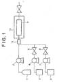
- FIG. 1 shows a simplified schematic drawing of an apparatus used for removing residues according to the present invention.
- the semiconductor wafer having residues on its surface is introduced to and placed in a high pressure vessel 9, then CO 2 is supplied from a CO 2 cylinder 1 to the high pressure vessel 9 by a high pressure pump 2.
- the high pressure vessel 9 isthermostated at a specific temperature by a thermostat 10 in order to maintain the pressurized CO 2 in the high pressure vessel 9 at the supercritical condition.
- An additive and a co-solvent are supplied to the high pressure vessel 9 from tanks 3 and 6 by high pressure pumps 4 and 7, respectively, while the additive and co-solvent are mixed by a line mixer 11 on the way to the high pressure vessel 9.
- the flow rates of the additive and the co-solvent are adjusted by valves 5 and 8, respectively in order to set to the predetermined values.
- the CO 2 , the additive and the co-solvent may be supplied continuously.
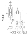
- Figure 2 shows another embodiment of the apparatus for removing residues according to the present invention.
- the additive is mixed with the co-solvent by the line mixer 11 before being fed into the high pressure vessel 9 in order to avoid heterogeneously contacting.
- the ratio of the additive and the co-solvent to be fed into the high pressure vessel 9 is controlled by a ratio controller 12, which regulates the feeding rate(s) of the additive and/or the co-solvent to the supercritical CO 2 in the high pressure vessel 9.
- the removing process is performed at a temperature in the range from 31°C to 210°C, and at a pressure ranged from 5 M Pa to 30 M Pa, preferably, from 7.1 M Pa to 20 M Pa.
- the time required for removing the residues depends on the size of the object, the kind and amount of the residues, which is usually in the range from a minute to several ten minutes.
- This experiment is carried out by dipping an object in an additive shown in table 1 at an atmospheric pressure at a temperature in the range of from 40°C to 100°C for 20 minutes.
- the object for this experiment is a silicon wafer having a SiO 2 layer coated with a novolac phenol type resist, patterned by a development, and treated to form microstructures on its surface by dry etching of a fluorine gas.
- a rate of removing residues is estimated as a ratio of an area of the surface adhering with residues after removing and before removing by a microscope.
- ⁇ and the term “ ⁇ ” mean that the rate is less than 90%, and 90% or more, respectively.
- the term " ⁇ " means the rate is 90% or more when the additive is diluted ten times by a co-solvent such as dimethylsulfoxide.
- alkylamine such as methylamine and ethylamine
- alkanolamine such as monoethanolamine
- quaternary ammonium hydroxide such as TMAH and choline
- hydroxylamine and ammonium fluoride
- quaternary ammonium hydroxide,hydroxylamine, and ammonium fluoride have a superior rate for removing residues.
- experiment No. 2-1-2-9 As shown in table 2, in experiment No. 2-1-2-9, the effects of co-solvents are confirmed.
- the conditions in experiment No. 2-1-2-9 observed through the window are transparent, homogenous, and without two phases.
- This experiment for removing residues from the surface of semiconductor wafers is carried out by using a remover including additives H, I, G, J, L, and K which include the fluoride of formula NR1R2R3R4F (R represents a hydrogen or alkyl group).
- the compositions of the additives are listed in Table 4.
- compositions of Additive Additive Fluoride (wt % of additive) Other components (wt % of additive) H TMAF (13.43) DMAC(62.5) DIW (24.07) I TMAF (4.48) DMAC (67.5) DIW (28.02) G NH 4 F (5.0) DMAC (64.2) DIW(12.4), AcOH (8.0), NH 4 OAc (10.4) J TBAF (25) DMAC (43) Ethanol (32) L TBAF (32) DMAC (39) Ethanol (29) K TMAF (5) DMAC (62.5) Ethanol (32.5) DMAC:Dimethylacetamide, DIW:De-ionized water, TMAF: Tetramethylammoniumfluoride, PG: Propyleneglycol, DMSO: Dimethylsulfoxide, AcOH: Acetic acid, TBAF: Tetrabutylammoniumfluoride, NH 4 OAc: ammonium acetate.
- silicon wafers A, B and C are used. These silicon wafers have different patterns on their surfaces and the removing characteristics of their resists are also different.
- the silicon wafers are prepared to generate the thermal oxides of silicon on the surface thereof and broken into chips (1cm x 1cm). The chips are etched in the fluoride gas. Then the resists on the chips are ashed by a plasma to generate ashed resists.
- the chips are placed in the high pressure vessel 9.
- the solutions of additives H, I, G, J, K and L are prepared such that the fluoride is dissolved in the other components listed in the table 4, respectively. Then, such additives are introduced with CO 2 and ethanol into the high pressure vessel in Fig. 1.
- the temperature of CO 2 in the high pressure vessel 9 is 40°C
- the pressure is 15 M Pa
- the time for making the chips contact with CO 2 is 3 minutes. After taken out from the high pressure vessel 9, the chips are observed with an electron microscope.
- the ashed resists on the wafer-A are cleaned by both 0.05wt% of H and I with 5wt% ethanol dissolved in the supercritical CO 2 .
- the term "Excellent” means that there is no residues on the surface of the silicon wafer (chips).
- the term “Fair” means that there are a few residues on the surface or a little disappearance of the pattern.
- a water rinse is needed to remove residue since a water-soluble residue newly appears on the surface of the silicon wafer (chips).
- Runs 1 to 7 and 9 to 14 the water rinsing step subsequent to the removing step is not needed. In these cases, a solvent including CO 2 and alcohol, e.g.
- Wafer-C contains more difficult ashed resists to be removed from the surface of the silicon wafer (chips). In order to remove this resist, longer removing time (three times longer than wafer-B) is required. The result is excellent.
- the silicon wafers are prepared to generate the thermal oxides of silicon on their surface and are broken into chips.
- the chips are placed in the high pressure vessel 9 in Fig. 1.
- a remover including CO 2 , the additives, and ethanol is introduced into the high pressure vessel 9.
- the chips are taken out and the thickness of the thermal oxides on the chips is measured by an ellipseometer.
- the etch rate of the thermal oxides is determined by dividing the decrease of the thickness per the treatment time.
- the temperature of CO 2 at the supercritical condition is 40C
- the pressure is 15 M Pa
- the treatment time is 20 to 60 minutes.
Abstract
Description
- The present invention relates to a process and an apparatus for removing residues from the microstructure of an object. The present invention specifically relates to a process and an apparatus for removing residues, such as resists, generated during a semiconductor manufacturing process from a semiconductor wafer surface having a fine structure of convex and concave portions.
- It is required as one step in manufacturing a semiconductor wafer to remove residues, such as photoresists, UV-hardened resists, X-ray hardened resists, ashed resists, carbon-fluorine containing polymer, plasma etch residues, and organic or inorganic contaminants from the other steps of the manufacturing process. The dry and wet removal methods are commonly used. In the wet removal method, the semiconductor wafer is dipped in an agent, such as a water solution, including a remover to remove residues from the surface of semiconductor wafer. Recently, supercritical CO2 is used as such an agent because of its low viscosity.
- However, supercritical CO2 is not enough by itself to remove several residues from the surface of the semiconductor wafer. To resolve this problem, several additives to supercritical CO2 are proposed. As described in the Japanese unexamined patent publication No. 10-125644, methane or a surfactant having a CFx group is used as an additive to supercritical CO2. In Japanese unexamined patent publication No. 8-191063, dimethylsulfoxide ordimethyl-formamide is used as such an additive. These additives are not always effective for removing residues.
- An object of the present invention is, therefore, to provide a process and an apparatus for effectively removing residues from the microstructure of an object.
- According to the present invention, a process is provided for removing residues from the object, which comprises steps of preparing a remover including a CO2, an additive for removing the residues and a co-solvent for dissolving said additive in said CO2 at a pressurized fluid condition, and bringing the object into contact with said remover so as to remove the residues from the object.
- A process is further provided for removing residues from the microstructure of an object, which comprises a step of contacting the object with a remover including a supercritical CO2, a compound having hydroxyl group, and a fluoride of formula NR1R2R3R4F, where R represents a hydrogen or alkyl group.
- An apparatus is further provided for removing residues from the object, which comprises a vessel, at least one inlet for feeding into said vessel a CO2, an additive for removing the residues and a co-solvent for dissolving said additive in said CO2, a pump for pressurizing CO2 into said vessel, and a heater for keeping said pressurized CO2 at a predetermined temperature.
- The foregoing and additional features and characteristics of the present invention will become more apparent from the following detailed description considered with reference to the accompanying drawings in which like reference numerals designate like elements and wherein:
- FIG. 1 is a schematic diagram of an apparatus for removing residues in accordance with the present invention.
- FIG. 2 is a schematic diagram of another embodiment of the apparatus for removing residues in accordance with the present invention.
- FIG. 3 shows an effect of the concentration of tetramethylammoniumfluoride (hereinafter referred to as "TMAF") on the etch rate.
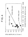
- FIG. 4 shows an effect of the concentration of ethanol on the etch rate.
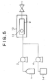
- FIG. 5 is a schematic diagram of a third embodiment of the apparatus for removing residues in accordance with the present invention.
-
- The present invention is applied to the microstructure of an object, e.g., a semiconductor wafer having a fine structure of convex and concave portions on its surface, and a substrate made of a metal, plastic or ceramic which forms or remains continuous or noncontinuous layer of materials different therefrom.
- As the pressurized CO2 is not enough by itself to remove residues, the pressurized CO2 of the present invention, to which an additive and a co-solvent are added, is used as a remover for removing residues from the object. The additive used for this purpose can remove residues but cannot substantially dissolve in CO2 by itself. The co-solvent used for this purpose can make the additive dissolved or dispersed homogeneously in CO2.
- The pressurized CO2 has a high dispersion rate and enables the dissolved residues to disperse therein. If CO2 is converted to a supercritical condition, it penetrates into fine pattern portions of the object more effectively. By this feature, the additive is conveyed into pores or concave portions on a surface of the object due to the low viscosity of CO2.
- The CO2 is pressurized to 5 MPa or more, but not less than 7.1 MPa at a temperature of 31°C to convert the CO2 to a supercritical fluid condition.
- The basic compound is preferably used as the additive because it effectively hydrolyzes polymers typically used as a resist in manufacturing a semiconductor. The preferred basic compound includes at least one element selected from the group consisting of quaternary ammoniumhydroxide, quaternary ammoniumfluoride, alkylamine, alkanolamine, hydroxylamine, and ammoniumfluoride. It is preferred to use a compound including at least one of quaternary ammoniumhydroxide, quaternary ammoniumfluoride hydroxylamine and ammoniumfluoride to remove novolac phenol resists from a semiconductor wafer. The quaternary ammoniumhydroxide may be any quaternary ammoniumhydroxide, e.g. tetramethylammoniumhydroxide, tetraethylammoniumhydroxide, tetrapropylammoniumhydroxide,tetrabutylammoniumhydroxide (hereinafter referred as TBAH), and choline. The quaternary ammoniumfluoride may be any quaternary ammoniumfluoride, e.g. tetramethylammoniumfluoride (hereinafter referred as TMAF), tetraethylammoniumfluoride, tetrapropylammoniumfluoride, tetrabutylammoniumfluoride, and cholinefluoride. The alkylamine may be any alkylamine, e.g. methylamine, dimethylamine, ethylamine, diethylamine, triethylamine, and propylamine, dipropylamine. The alkanolamine may be any alkanolamine, e.g., monoethanolamine, diethanolamine, andtriethanolamine.
- The additive is preferably added in a ratio of not less than 0.001 wt. % of the remover, more preferably in a ratio of not less than 0.002 wt. %. When the additive is added in a ratio of more than 8 wt. %, the co-solvent should be added more, but the amount of CO2 is decreased according to the amount of the added co-solvent, which decreases the penetration of CO2 into a surface of the object. The upper range of the additive is 8 wt. %, preferably 6 wt. %, and more preferably 4 wt. %.
- According to the present invention, the co-solvent is added to CO2 together with the additive. The co-solvent of the present invention is a compound having an affinity to both CO2 and the additive. Such a co-solvent dissolves or disperses the additive homogeneously in the pressurized CO2 in fluid condition. An alcohol, dimethylsulfoxide or a mixture thereof is used as the co-solvent. The alcohol may be any alcohol, e.g. ethanol, methanol, n-propanol, iso-propanol, n-butanol, iso-butanol, diethyleneglycolmonomethyleter, diethyleneglycolmonoethyleter, and hexafluoro isopropanol, preferably ethanol and methanol.
- The kind and amount of the co-solvent are selected depending on the kind and amount of the additive to CO2. The amount of the co-solvent is preferably five times or more than that of the additive because the remover easily becomes homogeneous and transparent. Alternatively, the remover may include the co-solvent in a range of 1 wt. % to 50 wt. %. If more than 50 wt. % of the co-solvent is added, the penetration rate of the remover decreases due to less amount of CO2. It is preferable to use a remover including CO2, alcohol as the co-solvent, quaternary ammoniumfluoride and/or quaternary ammoniumhydroxide as the additive because these additives are well dissolved in CO2 by alcohol and are CO2-philic. According to the present invention, it is preferable to contact the object with a remover composed of CO2, a fluoride of formula NR1R2R3R4F, (R represents a hydrogen or alkyl group), and a compound having hydroxyl group, while CO2 is high pressurized or is preferably kept at a supercritical condition. This remover is more effective to remove ashed residues from the semiconductor wafer. The fluoride may be any fluoride of formula NR1R2R3R4F where R represents a hydrogen or alkyl group, e.g. ammonium fluoride, tetramethylammoniumfluoride, and tetraethylammoniumfluoride. It is preferable to use the fluoride with Rs being alkyl groups, such as tetramethylammoniumfluoride andtetraethylammoniumfluoride because such fluorides are CO2-philic. In the present invention, the remover may include the fluoride preferably in the range from 0.001 wt % to 5 wt % of the remover, more preferably in the range from 0.002 wt % to 0.02 wt % of the remover.
- The fluoride is used as the additive to supercritical CO2 in the presence of a compound having a hydroxyl group, e.g., alcohol (such as ethanol, methanol, n-propanol, isopropanol, n-butanol and isobutanol , phenol), glycol (such as ethylenglycol and methylenglycol and polyethylenglycol). The alcohol is preferred because it effectively dissolves or disperses the fluoride, such as TMAF, homogeneously in supercritical CO2. Among alcohol, ethanol is preferable because a larger amount of the fluoride, such as TMAF, can be dissolved in supercritical CO2 by the presence of the ethanol. The concentration of the compound in supercritical CO2 depends on the kind and concentration of the fluoride, and the kind of the residue. Approximately, the compound is preferably included in supercritical CO2 in the range from 1 wt % to 20 wt % of the remover.
- It is preferable that the supercritical CO2 further comprises dimethylacetamide (hereinafter referred to as "DMAC"). The DMAC contained in the CO2 is preferably six to seventy times of the fluoride contained in the CO2 by weight. Further, it is preferable that the supercritical CO2 includes substantially no water, which is a hindrance for manufacturing semiconductor wafers.
- Figure 1 shows a simplified schematic drawing of an apparatus used for removing residues according to the present invention. Firstly, the semiconductor wafer having residues on its surface is introduced to and placed in a
high pressure vessel 9, then CO2 is supplied from a CO2 cylinder 1 to thehigh pressure vessel 9 by ahigh pressure pump 2. Thehigh pressure vessel 9 isthermostated at a specific temperature by athermostat 10 in order to maintain the pressurized CO2 in thehigh pressure vessel 9 at the supercritical condition. An additive and a co-solvent are supplied to thehigh pressure vessel 9 fromtanks line mixer 11 on the way to thehigh pressure vessel 9. The flow rates of the additive and the co-solvent are adjusted byvalves - Figure 2 shows another embodiment of the apparatus for removing residues according to the present invention. In this apparatus, the additive is mixed with the co-solvent by the
line mixer 11 before being fed into thehigh pressure vessel 9 in order to avoid heterogeneously contacting. The ratio of the additive and the co-solvent to be fed into thehigh pressure vessel 9 is controlled by aratio controller 12, which regulates the feeding rate(s) of the additive and/or the co-solvent to the supercritical CO2 in thehigh pressure vessel 9. - The removing process is performed at a temperature in the range from 31°C to 210°C, and at a pressure ranged from 5 M Pa to 30 M Pa, preferably, from 7.1 M Pa to 20 M Pa. The time required for removing the residues depends on the size of the object, the kind and amount of the residues, which is usually in the range from a minute to several ten minutes.
- Hereinafter, the present invention is described with reference to experiments.
- This experiment is carried out by dipping an object in an additive shown in table 1 at an atmospheric pressure at a temperature in the range of from 40°C to 100°C for 20 minutes. The object for this experiment is a silicon wafer having a SiO2 layer coated with a novolac phenol type resist, patterned by a development, and treated to form microstructures on its surface by dry etching of a fluorine gas. A rate of removing residues is estimated as a ratio of an area of the surface adhering with residues after removing and before removing by a microscope. The term "×" and the term "○" mean that the rate is less than 90%, and 90% or more, respectively. The term "Ø" means the rate is 90% or more when the additive is diluted ten times by a co-solvent such as dimethylsulfoxide.
- The results are summarized in table 1.
Additive Removability Acetone × Dimethylformamide × Dimethylsulfoxide × N-methyl-2-pyroridon × Propylencarbonate × Methylamine ○ Ethylamine ○ Monoethanolamine ○ Hydroxytetramethylammonium solution Ø Choline solution Ø Hydroxylamine solution Ø Ammonium fluoride solution Ø - As shown in table 1, alkylamine (such as methylamine and ethylamine) , alkanolamine (such as monoethanolamine), quaternary ammonium hydroxide (such as TMAH and choline), hydroxylamine, and ammonium fluoride have high removability. Especially, quaternary ammonium hydroxide,hydroxylamine, and ammonium fluoride have a superior rate for removing residues.
- This experiment for investigating an effect of co-solvent on a solubility of additive in CO2 is carried out via the apparatus shown in Fig. 5. CO2 is introduced into the
vessel 9 from the CO2 cylinder 1 by thepump 2. The pressure and the temperature in the vessel are maintained at 20 MPa and 80°C by thethermostat 10. The additive and co-solvent are mixed in the ratio shown in table 2, then the mixture is introduced into thevessel 9 from the mixingtank 14 by thepump 4. The same amount of CO2 as the mixture is evacuated from thevessel 9 so that the pressure is maintained at 20 MPa when the mixture is introduced. The effect of co-solvent, i.e., whether the additive is dissolved in CO2, is observed through theglass window 13 of thevessel 9. When the additive is not dissolved in CO2, two phases are observed through the window. The term "×" in table 2 means that the two phases are observed. The term "O" means the co-solvent makes the additive dissolved or dispersed homogeneously in CO2 (the two phases are not observed).Exp. No. Additive Co-solvent Observation wt % wt % 2-1 TMAH 1.21 ethanol 22.1 ○ 2-2 TMAH 1.50 dimethylsulfoxide 30.0 ○ 2-3 TBAH 0.40 ethanol 38.1 ○ 2-4 choline 0.05 ethanol 20.0 ○ 2-5 choline 1.76 ethanol 35.3 ○ 2-6 choline 0.25 ethanol 24.0 ○ 2-7 choline 0.29 isopropanol 27.9 ○ 2-8 choline 0.39 DEGME 38.3 ○ 2-9 Mono-ethanolamine 0.05 ethanol 25.0 ○ 2-10 Non Non ○ 2-11 Non ethanol 20.0 ○ 2-12 choline 0.05 Non × DEGME: diethyleneglycolmethylether - As shown in table 2, in experiment No. 2-1-2-9, the effects of co-solvents are confirmed. The conditions in experiment No. 2-1-2-9 observed through the window are transparent, homogenous, and without two phases.
- This experiment for removing residues using a remover including high pressure CO2, additive(s), and co-solvent(s) is carried out via the apparatus of Fig. 1. The object in this experiment is the same as the one in the
experiment 1. The kind and concentration of the additive and co-solvent in the remover are shown in table 3. The terms"Ø", "○" and "×" in table 3 indicate the rate of removing residues being 90% or more, 60% or more, and 10% or less, respectively.Exp. No. Additive Co-solvent Rate Wt% Wt% 3-1 Choline 0.05 Ethanol 20.0 ○ 3-2 Choline 1.70 Ethanol 35.3 Ø 3-3 TMAH 1.21 Methanol 22.2 Ø 3-4 TMAH 1.50 Dimethylsulfoxide 30.0 Ø 3-5 Non Non × 3-6 Non Ethanol 20.0 × 3-7 Non dimethylsulfoxide 30.0 × - As shown in table 3, in the experiment No. 3-1-3-4, the residues are effectively removed.
- This experiment for removing residues from the surface of semiconductor wafers is carried out by using a remover including additives H, I, G, J, L, and K which include the fluoride of formula NR1R2R3R4F (R represents a hydrogen or alkyl group). The compositions of the additives are listed in Table 4.
Compositions of Additive Additive Fluoride (wt % of additive) Other components (wt % of additive) H TMAF (13.43) DMAC(62.5) DIW (24.07) I TMAF (4.48) DMAC (67.5) DIW (28.02) G NH4F (5.0) DMAC (64.2) DIW(12.4), AcOH (8.0), NH4OAc (10.4) J TBAF (25) DMAC (43) Ethanol (32) L TBAF (32) DMAC (39) Ethanol (29) K TMAF (5) DMAC (62.5) Ethanol (32.5) DMAC:Dimethylacetamide, DIW:De-ionized water, TMAF: Tetramethylammoniumfluoride, PG: Propyleneglycol, DMSO: Dimethylsulfoxide, AcOH: Acetic acid, TBAF: Tetrabutylammoniumfluoride, NH4OAc: ammonium acetate. - In this experiment, three kinds of silicon wafers A, B and C are used. These silicon wafers have different patterns on their surfaces and the removing characteristics of their resists are also different. The silicon wafers are prepared to generate the thermal oxides of silicon on the surface thereof and broken into chips (1cm x 1cm). The chips are etched in the fluoride gas. Then the resists on the chips are ashed by a plasma to generate ashed resists. The chips are placed in the
high pressure vessel 9. The solutions of additives H, I, G, J, K and L are prepared such that the fluoride is dissolved in the other components listed in the table 4, respectively. Then, such additives are introduced with CO2 and ethanol into the high pressure vessel in Fig. 1. The temperature of CO2 in thehigh pressure vessel 9 is 40°C, the pressure is 15 M Pa, and the time for making the chips contact with CO2 is 3 minutes. After taken out from thehigh pressure vessel 9, the chips are observed with an electron microscope. - The result of this experiment is summarized in Table 5.
Run Wafer Additive Conc. in Remover [wt%] Result Additive Ethanol 1 A H 0.05 5 Excellent 2 A I 0.05 5 Excellent 3 B H 0.05 5 Fair 4 B H 0.10 5 Excellent 5 B H 0.25 5 Fair 6 B I 0.05 5 Fair 7 C H 0.10 5 Excellent 8 A G 0.05 5 Fair, but water rinse needs to remove the residue newly appeared 9 A J 0.05 5 Excellent 10 A K 0.05 5 Excellent 11 A L 0.05 5 Excellent 12 B J 0.10 5 Excellent 13 B K 0.10 5 Excellent 14 B L 0.10 5 Excellent - The ashed resists on the wafer-A are cleaned by both 0.05wt% of H and I with 5wt% ethanol dissolved in the supercritical CO2. The term "Excellent" means that there is no residues on the surface of the silicon wafer (chips). The term "Fair" means that there are a few residues on the surface or a little disappearance of the pattern. In
Run 8 using NH4F, a water rinse is needed to remove residue since a water-soluble residue newly appears on the surface of the silicon wafer (chips). InRuns 1 to 7 and 9 to 14, the water rinsing step subsequent to the removing step is not needed. In these cases, a solvent including CO2 and alcohol, e.g. methanol and ethanol, but no water is preferably used for rinsing the silicon wafer. Further, in cases of the additives J, K and L, no water is substantially needed in both steps of removing and rinsing. Such method is superior because it uses substantially no water which becomes a hindrance for manufacturing semiconductor wafers. - Wafer-C contains more difficult ashed resists to be removed from the surface of the silicon wafer (chips). In order to remove this resist, longer removing time (three times longer than wafer-B) is required. The result is excellent.
- The silicon wafers are prepared to generate the thermal oxides of silicon on their surface and are broken into chips. The chips are placed in the
high pressure vessel 9 in Fig. 1. Then, a remover including CO2, the additives, and ethanol is introduced into thehigh pressure vessel 9. After the removal treatment for several ten minutes, the chips are taken out and the thickness of the thermal oxides on the chips is measured by an ellipseometer. The etch rate of the thermal oxides is determined by dividing the decrease of the thickness per the treatment time. The temperature of CO2 at the supercritical condition is 40C, the pressure is 15 M Pa, and the treatment time is 20 to 60 minutes. - The result of this experiment is summarized in Table 6
Additive Concentration in Remover [wt%] Etch Rate of thermal oxides of silicon [A/min] additive Ethanol H 0.030 5.9 2.4 H 0.047 4.7 4.6 H 0.228 4.3 7.5 I 0.025 5.1 1.4 I 0.044 2.2 3.3 I 0.048 4.8 1.6 I 0.049 4.8 1.6 I 0.050 5.0 1.7 I 0.050 10.0 0.3 I 0.056 5.5 1.6 I 0.057 2.8 2.0 I 0.057 5.6 1.9 I 0.071 3.5 3.7 I 0.248 4.7 5.3 G 0.005 5.1 1.1 G 0.012 4.7 -0.1 G 0.028 5.5 3.9 G 0.039 5.1 8.3 G 0.043 4.2 7.9 G 0.044 4.4 5.1 - These data in table 6 are plotted in Figures 3 and 4. As shown in Figure 3, the etch rate of thermal oxides depends on the concentration of additives. Besides, as shown in Figure 4, if the concentration of the additive is constant, the etch rate varies according to the ethanol concentration. The etch rate can be controlled according to the removing objects or the removing process. As seen from Figures 3 and 4, the etch rate is controlled by adjusting the concentrations of the additive and ethanol, and their ratio.
Claims (16)
- A composition for removing residues from the microstructure of an object, comprising:carbon dioxide;an additive for removing the residues comprising a fluoride having the formula NR1R2R3R4F, where R1, R2, R3 and R4 are each independently a hydrogen or an alkyl group; anda co-solvent for dissolving said additive in said carbon dioxide at a pressurized fluid condition.
- The composition according to claim 1, wherein R1, R2, R3 and R4 are hydrogen.
- The composition according to claim 1, wherein R1, R2, R3 and R4 are an alkyl.
- The composition according to claim 1, wherein the fluoride having the formula NR1R2R3R4F is selected from the group consisting of tetramethylammonium fluoride, tetraethylammonium fluoride, tetrapropylammonium fluoride, tetrabutylammonium fluoride and choline fluoride.
- The composition according to anyone of claims 1 to 4, wherein said co-solvent is an alcohol, dimethylsulfoxide or a mixture thereof.
- The composition according to anyone of claims 1 to 4, wherein said co-solvent is a compound having a hydroxyl group.
- The composition according to claim 6, wherein said compound having a hydroxyl group is an alcohol or a glycol.
- The composition according to claim 7, wherein said compound having a hydroxyl group is selected from the group consisting of methanol, ethanol, n-propanol, iso-propanol, n-butanol, iso-butanol, diethylene-glycolmonomethylether, diethyleneglycolmonoethylether, hexafluoro iso-propanol, phenol, methylene glycol, ethylene glycol, propylene glycol and polyethylene glycol.
- The composition according to any one of claims 1 to 8, wherein said additive further comprises a basic compound, wherein said basic compound is at least one element selected from the group consisting of quaternary ammonium hydroxide, alkylamine, alkanolamine and hydroxylamine.
- The composition according to any one of claims 1 to 9, wherein said co-solvent further comprises one or more of de-ionized water, dimethylacetamide, ammonium acetate and acetic acid.
- The composition according to any one of claims 1 to 10, wherein said composition comprises de-ionized water.
- The composition according to any one of claims 1 to 10, wherein said composition is substantially free of water.
- The composition according to any one of claims 1 to 12, wherein said carbon dioxide is converted to a supercritical condition.
- The composition according to any one of claims 1 to 13, wherein said additive is present in said composition in the range of from 0.001 wt% to 8 wt%.
- The composition according to any one of claims 1 to 14, wherein the co-solvent is present in the composition in the range of from 1 wt% to 50 wt%.
- The composition according to any one of claims 1 to 15, wherein the residues are selected from photoresists, UV-hardened resists, X-ray hardened resists, ashed resists, carbon-fluorine containing polymer, plasma etch residues, and organic or inorganic contaminants.
Applications Claiming Priority (3)
| Application Number | Priority Date | Filing Date | Title |
|---|---|---|---|
| JP2001034337 | 2001-02-09 | ||
| JP2001034337A JP2002237481A (en) | 2001-02-09 | 2001-02-09 | Method of cleaning microscopic structure |
| EP02736487A EP1358670B1 (en) | 2001-02-09 | 2002-02-08 | Process for removing residues from the microstructure of an object |
Related Parent Applications (1)
| Application Number | Title | Priority Date | Filing Date |
|---|---|---|---|
| EP02736487A Division EP1358670B1 (en) | 2001-02-09 | 2002-02-08 | Process for removing residues from the microstructure of an object |
Publications (3)
| Publication Number | Publication Date |
|---|---|
| EP1457550A2 true EP1457550A2 (en) | 2004-09-15 |
| EP1457550A3 EP1457550A3 (en) | 2004-11-03 |
| EP1457550B1 EP1457550B1 (en) | 2006-07-05 |
Family
ID=18897963
Family Applications (2)
| Application Number | Title | Priority Date | Filing Date |
|---|---|---|---|
| EP04011792A Expired - Lifetime EP1457550B1 (en) | 2001-02-09 | 2002-02-08 | Composition for removing residues from the microstructure of an object |
| EP02736487A Expired - Lifetime EP1358670B1 (en) | 2001-02-09 | 2002-02-08 | Process for removing residues from the microstructure of an object |
Family Applications After (1)
| Application Number | Title | Priority Date | Filing Date |
|---|---|---|---|
| EP02736487A Expired - Lifetime EP1358670B1 (en) | 2001-02-09 | 2002-02-08 | Process for removing residues from the microstructure of an object |
Country Status (10)
| Country | Link |
|---|---|
| US (3) | US20030106573A1 (en) |
| EP (2) | EP1457550B1 (en) |
| JP (2) | JP2002237481A (en) |
| KR (2) | KR100482496B1 (en) |
| CN (2) | CN1243366C (en) |
| AT (2) | ATE332571T1 (en) |
| DE (2) | DE60212937T2 (en) |
| SG (1) | SG125957A1 (en) |
| TW (1) | TW569328B (en) |
| WO (1) | WO2002080233A2 (en) |
Cited By (1)
| Publication number | Priority date | Publication date | Assignee | Title |
|---|---|---|---|---|
| EP1572833A1 (en) * | 2002-10-31 | 2005-09-14 | Advanced Technology Materials, Inc. | Supercritical carbon dioxide/chemical formulation for ashed and unashed aluminum post-etch residue removal |
Families Citing this family (36)
| Publication number | Priority date | Publication date | Assignee | Title |
|---|---|---|---|---|
| US7064070B2 (en) * | 1998-09-28 | 2006-06-20 | Tokyo Electron Limited | Removal of CMP and post-CMP residue from semiconductors using supercritical carbon dioxide process |
| AU2001255656A1 (en) * | 2000-04-25 | 2001-11-07 | Tokyo Electron Limited | Method of depositing metal film and metal deposition cluster tool including supercritical drying/cleaning module |
| JP3978023B2 (en) * | 2001-12-03 | 2007-09-19 | 株式会社神戸製鋼所 | High pressure processing method |
| US7557073B2 (en) * | 2001-12-31 | 2009-07-07 | Advanced Technology Materials, Inc. | Non-fluoride containing supercritical fluid composition for removal of ion-implant photoresist |
| US7326673B2 (en) | 2001-12-31 | 2008-02-05 | Advanced Technology Materials, Inc. | Treatment of semiconductor substrates using long-chain organothiols or long-chain acetates |
| US20040016450A1 (en) * | 2002-01-25 | 2004-01-29 | Bertram Ronald Thomas | Method for reducing the formation of contaminants during supercritical carbon dioxide processes |
| JP2003224099A (en) | 2002-01-30 | 2003-08-08 | Sony Corp | Surface treatment method |
| JP2006508521A (en) * | 2002-02-15 | 2006-03-09 | 東京エレクトロン株式会社 | Drying of resist using solvent bath and supercritical CO2 |
| AU2003220039A1 (en) * | 2002-03-04 | 2003-09-22 | Supercritical Systems Inc. | Method of passivating of low dielectric materials in wafer processing |
| AU2003220443A1 (en) * | 2002-03-22 | 2003-10-13 | Supercritical Systems Inc. | Removal of contaminants using supercritical processing |
| US7169540B2 (en) * | 2002-04-12 | 2007-01-30 | Tokyo Electron Limited | Method of treatment of porous dielectric films to reduce damage during cleaning |
| US6764552B1 (en) * | 2002-04-18 | 2004-07-20 | Novellus Systems, Inc. | Supercritical solutions for cleaning photoresist and post-etch residue from low-k materials |
| JP2003318810A (en) * | 2002-04-26 | 2003-11-07 | Kobe Steel Ltd | Radio data collection system and radio data repeater |
| US6669785B2 (en) * | 2002-05-15 | 2003-12-30 | Micell Technologies, Inc. | Methods and compositions for etch cleaning microelectronic substrates in carbon dioxide |
| US20030217764A1 (en) * | 2002-05-23 | 2003-11-27 | Kaoru Masuda | Process and composition for removing residues from the microstructure of an object |
| US6800142B1 (en) * | 2002-05-30 | 2004-10-05 | Novellus Systems, Inc. | Method for removing photoresist and post-etch residue using activated peroxide followed by supercritical fluid treatment |
| JP2004128251A (en) * | 2002-10-03 | 2004-04-22 | Elpida Memory Inc | Machine and method for coating |
| US7485611B2 (en) * | 2002-10-31 | 2009-02-03 | Advanced Technology Materials, Inc. | Supercritical fluid-based cleaning compositions and methods |
| JP2004158534A (en) * | 2002-11-05 | 2004-06-03 | Kobe Steel Ltd | Method for cleaning microscopic structure |
| US20040177867A1 (en) * | 2002-12-16 | 2004-09-16 | Supercritical Systems, Inc. | Tetra-organic ammonium fluoride and HF in supercritical fluid for photoresist and residue removal |
| US20040112409A1 (en) * | 2002-12-16 | 2004-06-17 | Supercritical Sysems, Inc. | Fluoride in supercritical fluid for photoresist and residue removal |
| JP4248903B2 (en) | 2003-03-19 | 2009-04-02 | 大日本スクリーン製造株式会社 | High pressure processing apparatus and high pressure processing method |
| US20040231707A1 (en) * | 2003-05-20 | 2004-11-25 | Paul Schilling | Decontamination of supercritical wafer processing equipment |
| KR100505693B1 (en) * | 2003-06-26 | 2005-08-03 | 삼성전자주식회사 | Cleaning method of photoresist or organic material from microelectronic device substrate |
| JP2005033135A (en) * | 2003-07-11 | 2005-02-03 | Kobe Steel Ltd | Cleaning device for microstructure |
| US20050022850A1 (en) * | 2003-07-29 | 2005-02-03 | Supercritical Systems, Inc. | Regulation of flow of processing chemistry only into a processing chamber |
| US20050039775A1 (en) * | 2003-08-19 | 2005-02-24 | Whitlock Walter H. | Process and system for cleaning surfaces of semiconductor wafers |
| JP4757452B2 (en) * | 2004-04-02 | 2011-08-24 | 昭和炭酸株式会社 | Gas-liquid separator |
| US7195676B2 (en) * | 2004-07-13 | 2007-03-27 | Air Products And Chemicals, Inc. | Method for removal of flux and other residue in dense fluid systems |
| US20060081273A1 (en) * | 2004-10-20 | 2006-04-20 | Mcdermott Wayne T | Dense fluid compositions and processes using same for article treatment and residue removal |
| US7550075B2 (en) * | 2005-03-23 | 2009-06-23 | Tokyo Electron Ltd. | Removal of contaminants from a fluid |
| US7789971B2 (en) | 2005-05-13 | 2010-09-07 | Tokyo Electron Limited | Treatment of substrate using functionalizing agent in supercritical carbon dioxide |
| JP2007142335A (en) * | 2005-11-22 | 2007-06-07 | Dainippon Screen Mfg Co Ltd | High-pressure treatment method |
| JP4179378B2 (en) * | 2007-01-04 | 2008-11-12 | トヨタ自動車株式会社 | VEHICLE DRIVE CONTROL DEVICE AND VEHICLE |
| JP6682272B2 (en) | 2013-01-15 | 2020-04-15 | ローレンス リバモア ナショナル セキュリティー, エルエルシー | Laser driven hot water treatment |
| FR3021554A1 (en) * | 2014-05-28 | 2015-12-04 | Dfd Dense Fluid Degreasing | METHOD AND DEVICE FOR SUPERCRITICAL FLUID TREATMENT WITH ADDITIVE INJECTION |
Citations (5)
| Publication number | Priority date | Publication date | Assignee | Title |
|---|---|---|---|---|
| WO2001033613A2 (en) * | 1999-11-02 | 2001-05-10 | Tokyo Electron Limited | Removal of photoresist and residue from substrate using supercritical carbon dioxide process |
| US6242165B1 (en) * | 1998-08-28 | 2001-06-05 | Micron Technology, Inc. | Supercritical compositions for removal of organic material and methods of using same |
| US6306564B1 (en) * | 1997-05-27 | 2001-10-23 | Tokyo Electron Limited | Removal of resist or residue from semiconductors using supercritical carbon dioxide |
| WO2002015251A1 (en) * | 2000-08-14 | 2002-02-21 | Tokyo Electron Limited | Removal of photoresist and photoresist residue from semiconductors using supercritical carbon dioxide process |
| EP1365441A1 (en) * | 2002-05-23 | 2003-11-26 | Kabushiki Kaisha Kobe Seiko Sho (Kobe Steel, Ltd.) | Process and composition for removing residues from the microstructure of an object |
Family Cites Families (18)
| Publication number | Priority date | Publication date | Assignee | Title |
|---|---|---|---|---|
| US5339844A (en) * | 1992-08-10 | 1994-08-23 | Hughes Aircraft Company | Low cost equipment for cleaning using liquefiable gases |
| US5456759A (en) * | 1992-08-10 | 1995-10-10 | Hughes Aircraft Company | Method using megasonic energy in liquefied gases |
| KR0137841B1 (en) * | 1994-06-07 | 1998-04-27 | 문정환 | Method for removing a etching waste material |
| JPH08330266A (en) * | 1995-05-31 | 1996-12-13 | Texas Instr Inc <Ti> | Method of cleansing and processing surface of semiconductor device or the like |
| US5868856A (en) * | 1996-07-25 | 1999-02-09 | Texas Instruments Incorporated | Method for removing inorganic contamination by chemical derivitization and extraction |
| US5868862A (en) * | 1996-08-01 | 1999-02-09 | Texas Instruments Incorporated | Method of removing inorganic contamination by chemical alteration and extraction in a supercritical fluid media |
| US5989353A (en) * | 1996-10-11 | 1999-11-23 | Mallinckrodt Baker, Inc. | Cleaning wafer substrates of metal contamination while maintaining wafer smoothness |
| US5908510A (en) * | 1996-10-16 | 1999-06-01 | International Business Machines Corporation | Residue removal by supercritical fluids |
| US6118000A (en) * | 1996-11-04 | 2000-09-12 | Hydrochem Industrial Services, Inc. | Methods for preparing quaternary ammonium salts |
| US5709756A (en) * | 1996-11-05 | 1998-01-20 | Ashland Inc. | Basic stripping and cleaning composition |
| US5983082A (en) * | 1997-10-31 | 1999-11-09 | Motorola, Inc. | Phase quadrature signal generator having a variable phase shift network |
| US6200943B1 (en) * | 1998-05-28 | 2001-03-13 | Micell Technologies, Inc. | Combination surfactant systems for use in carbon dioxide-based cleaning formulations |
| SG77710A1 (en) * | 1998-09-09 | 2001-01-16 | Tokuyama Corp | Photoresist ashing residue cleaning agent |
| US6277753B1 (en) * | 1998-09-28 | 2001-08-21 | Supercritical Systems Inc. | Removal of CMP residue from semiconductors using supercritical carbon dioxide process |
| CA2255413A1 (en) * | 1998-12-11 | 2000-06-11 | Fracmaster Ltd. | Foamed nitrogen in liquid co2 for fracturing |
| US6828289B2 (en) * | 1999-01-27 | 2004-12-07 | Air Products And Chemicals, Inc. | Low surface tension, low viscosity, aqueous, acidic compositions containing fluoride and organic, polar solvents for removal of photoresist and organic and inorganic etch residues at room temperature |
| US6425956B1 (en) * | 2001-01-05 | 2002-07-30 | International Business Machines Corporation | Process for removing chemical mechanical polishing residual slurry |
| US7326673B2 (en) * | 2001-12-31 | 2008-02-05 | Advanced Technology Materials, Inc. | Treatment of semiconductor substrates using long-chain organothiols or long-chain acetates |
-
2001
- 2001-02-09 JP JP2001034337A patent/JP2002237481A/en active Pending
-
2002
- 2002-02-08 EP EP04011792A patent/EP1457550B1/en not_active Expired - Lifetime
- 2002-02-08 DE DE60212937T patent/DE60212937T2/en not_active Expired - Lifetime
- 2002-02-08 AT AT02736487T patent/ATE332571T1/en not_active IP Right Cessation
- 2002-02-08 EP EP02736487A patent/EP1358670B1/en not_active Expired - Lifetime
- 2002-02-08 CN CNB028002741A patent/CN1243366C/en not_active Expired - Fee Related
- 2002-02-08 DE DE60212999T patent/DE60212999T2/en not_active Expired - Fee Related
- 2002-02-08 KR KR10-2002-7013494A patent/KR100482496B1/en not_active IP Right Cessation
- 2002-02-08 TW TW091102499A patent/TW569328B/en not_active IP Right Cessation
- 2002-02-08 CN CNA2004100447914A patent/CN1542910A/en active Pending
- 2002-02-08 US US10/240,848 patent/US20030106573A1/en not_active Abandoned
- 2002-02-08 JP JP2002578549A patent/JP3996513B2/en not_active Expired - Fee Related
- 2002-02-08 AT AT04011792T patent/ATE332355T1/en not_active IP Right Cessation
- 2002-02-08 WO PCT/US2002/003608 patent/WO2002080233A2/en active IP Right Grant
- 2002-02-08 KR KR10-2004-7006269A patent/KR100490506B1/en not_active IP Right Cessation
- 2002-02-08 US US10/067,773 patent/US20020164873A1/en not_active Abandoned
- 2002-02-08 SG SG200402533A patent/SG125957A1/en unknown
-
2004
- 2004-04-09 US US10/820,695 patent/US20040198627A1/en not_active Abandoned
Patent Citations (5)
| Publication number | Priority date | Publication date | Assignee | Title |
|---|---|---|---|---|
| US6306564B1 (en) * | 1997-05-27 | 2001-10-23 | Tokyo Electron Limited | Removal of resist or residue from semiconductors using supercritical carbon dioxide |
| US6242165B1 (en) * | 1998-08-28 | 2001-06-05 | Micron Technology, Inc. | Supercritical compositions for removal of organic material and methods of using same |
| WO2001033613A2 (en) * | 1999-11-02 | 2001-05-10 | Tokyo Electron Limited | Removal of photoresist and residue from substrate using supercritical carbon dioxide process |
| WO2002015251A1 (en) * | 2000-08-14 | 2002-02-21 | Tokyo Electron Limited | Removal of photoresist and photoresist residue from semiconductors using supercritical carbon dioxide process |
| EP1365441A1 (en) * | 2002-05-23 | 2003-11-26 | Kabushiki Kaisha Kobe Seiko Sho (Kobe Steel, Ltd.) | Process and composition for removing residues from the microstructure of an object |
Cited By (2)
| Publication number | Priority date | Publication date | Assignee | Title |
|---|---|---|---|---|
| EP1572833A1 (en) * | 2002-10-31 | 2005-09-14 | Advanced Technology Materials, Inc. | Supercritical carbon dioxide/chemical formulation for ashed and unashed aluminum post-etch residue removal |
| EP1572833A4 (en) * | 2002-10-31 | 2006-03-15 | Advanced Tech Materials | Supercritical carbon dioxide/chemical formulation for ashed and unashed aluminum post-etch residue removal |
Also Published As
| Publication number | Publication date |
|---|---|
| TW569328B (en) | 2004-01-01 |
| JP2002237481A (en) | 2002-08-23 |
| EP1457550B1 (en) | 2006-07-05 |
| KR100490506B1 (en) | 2005-05-19 |
| WO2002080233A3 (en) | 2002-11-14 |
| CN1542910A (en) | 2004-11-03 |
| EP1358670A4 (en) | 2004-11-17 |
| US20020164873A1 (en) | 2002-11-07 |
| US20030106573A1 (en) | 2003-06-12 |
| EP1457550A3 (en) | 2004-11-03 |
| SG125957A1 (en) | 2006-10-30 |
| JP3996513B2 (en) | 2007-10-24 |
| EP1358670A2 (en) | 2003-11-05 |
| KR20040040490A (en) | 2004-05-12 |
| KR100482496B1 (en) | 2005-04-14 |
| EP1358670B1 (en) | 2006-07-05 |
| CN1457502A (en) | 2003-11-19 |
| CN1243366C (en) | 2006-02-22 |
| ATE332355T1 (en) | 2006-07-15 |
| US20040198627A1 (en) | 2004-10-07 |
| DE60212999T2 (en) | 2006-12-28 |
| DE60212937T2 (en) | 2007-12-06 |
| ATE332571T1 (en) | 2006-07-15 |
| DE60212937D1 (en) | 2006-08-17 |
| KR20020093896A (en) | 2002-12-16 |
| DE60212999D1 (en) | 2006-08-17 |
| JP2004519863A (en) | 2004-07-02 |
| WO2002080233A2 (en) | 2002-10-10 |
Similar Documents
| Publication | Publication Date | Title |
|---|---|---|
| EP1457550B1 (en) | Composition for removing residues from the microstructure of an object | |
| US7888301B2 (en) | Resist, barc and gap fill material stripping chemical and method | |
| US6777380B2 (en) | Compositions for cleaning organic and plasma etched residues for semiconductor devices | |
| EP1619557B1 (en) | Composition for removing photoresist and/or etching residue from a substrate and use thereof | |
| EP1688798B1 (en) | Aqueous based residue removers comprising fluoride | |
| EP1091254B1 (en) | Resist stripping composition | |
| KR100368193B1 (en) | Aqueous rinsing composition | |
| US7456140B2 (en) | Compositions for cleaning organic and plasma etched residues for semiconductor devices | |
| US20150097139A1 (en) | Compositions for use in semiconductor devices | |
| EP1365441A1 (en) | Process and composition for removing residues from the microstructure of an object | |
| WO2004008249A2 (en) | Compositions and method for removing photoresist and/or resist residue | |
| KR20080091844A (en) | Selective removal chemistries for semiconductor applications, methods of production and uses thereof | |
| EP3599633B1 (en) | Post etch residue cleaning compositions and methods of using the same | |
| KR100720249B1 (en) | Method for cleaning microstructure | |
| JP4167257B2 (en) | Residue removal composition | |
| US20080060682A1 (en) | High temperature spm treatment for photoresist stripping | |
| JP2005048189A (en) | Composition for removing residue | |
| KR100875586B1 (en) | Semiconductor substrates drying method using surfactants in supercritical carbon dioxide after wet etching | |
| KR102397091B1 (en) | Resist stripper composition and a method of stripping resist using the same |
Legal Events
| Date | Code | Title | Description |
|---|---|---|---|
| PUAI | Public reference made under article 153(3) epc to a published international application that has entered the european phase |
Free format text: ORIGINAL CODE: 0009012 |
|
| AC | Divisional application: reference to earlier application |
Ref document number: 1358670 Country of ref document: EP Kind code of ref document: P |
|
| AK | Designated contracting states |
Kind code of ref document: A2 Designated state(s): AT BE CH CY DE DK ES FI FR GB GR IE IT LI LU MC NL PT SE TR |
|
| PUAL | Search report despatched |
Free format text: ORIGINAL CODE: 0009013 |
|
| RAP1 | Party data changed (applicant data changed or rights of an application transferred) |
Owner name: AIR PRODUCTS AND CHEMICALS, INC. |
|
| AK | Designated contracting states |
Kind code of ref document: A3 Designated state(s): AT BE CH CY DE DK ES FI FR GB GR IE IT LI LU MC NL PT SE TR |
|
| RIC1 | Information provided on ipc code assigned before grant |
Ipc: 7G 03F 7/42 B Ipc: 7B 08B 3/00 B Ipc: 7C 11D 7/32 B Ipc: 7H 01L 21/00 B Ipc: 7C 11D 11/00 B Ipc: 7C 11D 1/00 B Ipc: 7C 11D 3/37 A |
|
| 17P | Request for examination filed |
Effective date: 20041216 |
|
| 17Q | First examination report despatched |
Effective date: 20050503 |
|
| AKX | Designation fees paid |
Designated state(s): AT BE CH CY DE DK ES FI FR GB GR IE IT LI LU MC NL PT SE TR |
|
| GRAP | Despatch of communication of intention to grant a patent |
Free format text: ORIGINAL CODE: EPIDOSNIGR1 |
|
| GRAS | Grant fee paid |
Free format text: ORIGINAL CODE: EPIDOSNIGR3 |
|
| GRAA | (expected) grant |
Free format text: ORIGINAL CODE: 0009210 |
|
| AC | Divisional application: reference to earlier application |
Ref document number: 1358670 Country of ref document: EP Kind code of ref document: P |
|
| AK | Designated contracting states |
Kind code of ref document: B1 Designated state(s): AT BE CH CY DE DK ES FI FR GB GR IE IT LI LU MC NL PT SE TR |
|
| PG25 | Lapsed in a contracting state [announced via postgrant information from national office to epo] |
Ref country code: IT Free format text: LAPSE BECAUSE OF FAILURE TO SUBMIT A TRANSLATION OF THE DESCRIPTION OR TO PAY THE FEE WITHIN THE PRESCRIBED TIME-LIMIT;WARNING: LAPSES OF ITALIAN PATENTS WITH EFFECTIVE DATE BEFORE 2007 MAY HAVE OCCURRED AT ANY TIME BEFORE 2007. THE CORRECT EFFECTIVE DATE MAY BE DIFFERENT FROM THE ONE RECORDED. Effective date: 20060705 Ref country code: BE Free format text: LAPSE BECAUSE OF FAILURE TO SUBMIT A TRANSLATION OF THE DESCRIPTION OR TO PAY THE FEE WITHIN THE PRESCRIBED TIME-LIMIT Effective date: 20060705 Ref country code: FI Free format text: LAPSE BECAUSE OF FAILURE TO SUBMIT A TRANSLATION OF THE DESCRIPTION OR TO PAY THE FEE WITHIN THE PRESCRIBED TIME-LIMIT Effective date: 20060705 Ref country code: LI Free format text: LAPSE BECAUSE OF FAILURE TO SUBMIT A TRANSLATION OF THE DESCRIPTION OR TO PAY THE FEE WITHIN THE PRESCRIBED TIME-LIMIT Effective date: 20060705 Ref country code: CH Free format text: LAPSE BECAUSE OF FAILURE TO SUBMIT A TRANSLATION OF THE DESCRIPTION OR TO PAY THE FEE WITHIN THE PRESCRIBED TIME-LIMIT Effective date: 20060705 Ref country code: AT Free format text: LAPSE BECAUSE OF FAILURE TO SUBMIT A TRANSLATION OF THE DESCRIPTION OR TO PAY THE FEE WITHIN THE PRESCRIBED TIME-LIMIT Effective date: 20060705 |
|
| REG | Reference to a national code |
Ref country code: GB Ref legal event code: FG4D |
|
| REG | Reference to a national code |
Ref country code: CH Ref legal event code: EP |
|
| REG | Reference to a national code |
Ref country code: IE Ref legal event code: FG4D |
|
| REF | Corresponds to: |
Ref document number: 60212999 Country of ref document: DE Date of ref document: 20060817 Kind code of ref document: P |
|
| PG25 | Lapsed in a contracting state [announced via postgrant information from national office to epo] |
Ref country code: DK Free format text: LAPSE BECAUSE OF FAILURE TO SUBMIT A TRANSLATION OF THE DESCRIPTION OR TO PAY THE FEE WITHIN THE PRESCRIBED TIME-LIMIT Effective date: 20061005 Ref country code: SE Free format text: LAPSE BECAUSE OF FAILURE TO SUBMIT A TRANSLATION OF THE DESCRIPTION OR TO PAY THE FEE WITHIN THE PRESCRIBED TIME-LIMIT Effective date: 20061005 |
|
| PG25 | Lapsed in a contracting state [announced via postgrant information from national office to epo] |
Ref country code: ES Free format text: LAPSE BECAUSE OF FAILURE TO SUBMIT A TRANSLATION OF THE DESCRIPTION OR TO PAY THE FEE WITHIN THE PRESCRIBED TIME-LIMIT Effective date: 20061016 |
|
| ET | Fr: translation filed | ||
| PG25 | Lapsed in a contracting state [announced via postgrant information from national office to epo] |
Ref country code: PT Free format text: LAPSE BECAUSE OF FAILURE TO SUBMIT A TRANSLATION OF THE DESCRIPTION OR TO PAY THE FEE WITHIN THE PRESCRIBED TIME-LIMIT Effective date: 20061205 |
|
| PGFP | Annual fee paid to national office [announced via postgrant information from national office to epo] |
Ref country code: GB Payment date: 20070105 Year of fee payment: 6 |
|
| PGFP | Annual fee paid to national office [announced via postgrant information from national office to epo] |
Ref country code: NL Payment date: 20070108 Year of fee payment: 6 |
|
| PG25 | Lapsed in a contracting state [announced via postgrant information from national office to epo] |
Ref country code: MC Free format text: LAPSE BECAUSE OF NON-PAYMENT OF DUE FEES Effective date: 20070228 |
|
| PLBE | No opposition filed within time limit |
Free format text: ORIGINAL CODE: 0009261 |
|
| STAA | Information on the status of an ep patent application or granted ep patent |
Free format text: STATUS: NO OPPOSITION FILED WITHIN TIME LIMIT |
|
| 26N | No opposition filed |
Effective date: 20070410 |
|
| PGFP | Annual fee paid to national office [announced via postgrant information from national office to epo] |
Ref country code: IT Payment date: 20070525 Year of fee payment: 6 |
|
| PG25 | Lapsed in a contracting state [announced via postgrant information from national office to epo] |
Ref country code: IE Free format text: LAPSE BECAUSE OF NON-PAYMENT OF DUE FEES Effective date: 20070208 |
|
| PG25 | Lapsed in a contracting state [announced via postgrant information from national office to epo] |
Ref country code: GR Free format text: LAPSE BECAUSE OF FAILURE TO SUBMIT A TRANSLATION OF THE DESCRIPTION OR TO PAY THE FEE WITHIN THE PRESCRIBED TIME-LIMIT Effective date: 20061006 |
|
| PGFP | Annual fee paid to national office [announced via postgrant information from national office to epo] |
Ref country code: FR Payment date: 20070201 Year of fee payment: 6 |
|
| GBPC | Gb: european patent ceased through non-payment of renewal fee |
Effective date: 20080208 |
|
| NLV4 | Nl: lapsed or anulled due to non-payment of the annual fee |
Effective date: 20080901 |
|
| PG25 | Lapsed in a contracting state [announced via postgrant information from national office to epo] |
Ref country code: NL Free format text: LAPSE BECAUSE OF NON-PAYMENT OF DUE FEES Effective date: 20080901 |
|
| REG | Reference to a national code |
Ref country code: FR Ref legal event code: ST Effective date: 20081031 |
|
| PG25 | Lapsed in a contracting state [announced via postgrant information from national office to epo] |
Ref country code: FR Free format text: LAPSE BECAUSE OF NON-PAYMENT OF DUE FEES Effective date: 20080229 |
|
| PGFP | Annual fee paid to national office [announced via postgrant information from national office to epo] |
Ref country code: DE Payment date: 20090227 Year of fee payment: 8 |
|
| PG25 | Lapsed in a contracting state [announced via postgrant information from national office to epo] |
Ref country code: GB Free format text: LAPSE BECAUSE OF NON-PAYMENT OF DUE FEES Effective date: 20080208 |
|
| PG25 | Lapsed in a contracting state [announced via postgrant information from national office to epo] |
Ref country code: LU Free format text: LAPSE BECAUSE OF NON-PAYMENT OF DUE FEES Effective date: 20070208 Ref country code: IT Free format text: LAPSE BECAUSE OF NON-PAYMENT OF DUE FEES Effective date: 20080208 Ref country code: CY Free format text: LAPSE BECAUSE OF FAILURE TO SUBMIT A TRANSLATION OF THE DESCRIPTION OR TO PAY THE FEE WITHIN THE PRESCRIBED TIME-LIMIT Effective date: 20060705 |
|
| PG25 | Lapsed in a contracting state [announced via postgrant information from national office to epo] |
Ref country code: TR Free format text: LAPSE BECAUSE OF FAILURE TO SUBMIT A TRANSLATION OF THE DESCRIPTION OR TO PAY THE FEE WITHIN THE PRESCRIBED TIME-LIMIT Effective date: 20060705 |
|
| PG25 | Lapsed in a contracting state [announced via postgrant information from national office to epo] |
Ref country code: DE Free format text: LAPSE BECAUSE OF NON-PAYMENT OF DUE FEES Effective date: 20100901 |