EP1306103A1 - Electrode assembly - Google Patents
Electrode assembly Download PDFInfo
- Publication number
- EP1306103A1 EP1306103A1 EP02090354A EP02090354A EP1306103A1 EP 1306103 A1 EP1306103 A1 EP 1306103A1 EP 02090354 A EP02090354 A EP 02090354A EP 02090354 A EP02090354 A EP 02090354A EP 1306103 A1 EP1306103 A1 EP 1306103A1
- Authority
- EP
- European Patent Office
- Prior art keywords
- electrode line
- electrode
- longitudinal guides
- longitudinal
- guides
- Prior art date
- Legal status (The legal status is an assumption and is not a legal conclusion. Google has not performed a legal analysis and makes no representation as to the accuracy of the status listed.)
- Granted
Links
Images


Classifications
-
- A—HUMAN NECESSITIES
- A61—MEDICAL OR VETERINARY SCIENCE; HYGIENE
- A61N—ELECTROTHERAPY; MAGNETOTHERAPY; RADIATION THERAPY; ULTRASOUND THERAPY
- A61N1/00—Electrotherapy; Circuits therefor
- A61N1/02—Details
- A61N1/04—Electrodes
- A61N1/05—Electrodes for implantation or insertion into the body, e.g. heart electrode
- A61N1/056—Transvascular endocardial electrode systems
Definitions
- the invention relates to an intravascular electrode arrangement comprising a first and second, for placement in blood vessels such as veins or Electrode line adapted to arteries, each with a stimulation and / or Sensing electrode in the area of a distal end of the respective Electrode line.
- the stimulation represents of the left heart is a problem because of placement intracardiac electrodes in the left heart is extremely complex. Therefore are used to stimulate the left atrium or ventricle instead intravascular electrodes used, for example in Coronary arteries are introduced. This results in problem described in the previous paragraph.
- This solution is based on the idea for the left atrium and the left ventricle of a heart each has its own intravascular Provide electrode catheters, each with respect to the different implantation locations are optimally designed.
- To implant this Electrode lines become the ventricular electrode line introduced. This is easily possible in the usual way, since the ventricular Electrode line has no guides. Then the atrial Electrode lead with its guides over the ventricular Electrode line pushed that the ventricular electrode line runs within the longitudinal guides. The atrial lead with their guides can then be advanced, passing through the ventricular lead is guided.
- the longitudinal guides In order to guide the first electrode line as precisely as possible allow, the longitudinal guides have eyelets that over the second Slide electrode lead and accordingly with respect to your Inner diameter to the outer diameter of the second Electrode line are adapted and this essentially correspond.
- the diameter of the two electrode lines is preferred less than 2mm so they can be used as intravascular electrode leads can be used.
- Electrode line with the outside longitudinal guides attached to the electrode line, which preferably comprise eyelets.
- the longitudinal guides preferably contain nitinol, a nickel-titanium alloy.
- the longitudinal guides have two in the longitudinal direction of the electrode line Ends, of which preferably at least one of the ends is one Inclined, starting from the electrode line to each other end is inclined.
- a variant is particularly preferred which both ends of the longitudinal guides are bevelled accordingly. A such a slope facilitates the insertion of the electrode line or Electrode assembly.
- the slope is Longitudinal guides of an open lattice structure or a wire mesh educated. This lattice structure or the wire mesh is especially after Designed like a stent.
- An electrode line in which the longitudinal guides are also preferred are subsequently applied to a sheath of the electrode line.
- the An alternative to this is in longitudinal guides made of the casing material themselves are formed, so that longitudinal guides and the shell of the Electrode line are integrally formed together.
- the sheath of the electrode line and Longitudinal guides different material for example, the shell of the Electrode lead formed from silicon-containing material while the Longitudinal guides essentially of nitinol-containing material, i.e. one Metal.
- the longitudinal guides have friction-reducing tongues on between which to hold the second electrode line provided cavity of the longitudinal guides and the sheath of the first electrode line arranged and such are formed so that a sheath of the second electrode line the tongues is at a distance from the sheath of the first electrode line.
- the immediate friction can the shells of the two electrode lines to each other largely be avoided so that the two electrode lines are as possible can be easily moved longitudinally relative to each other.
- tongue is in In this connection, every type of distance - imparting component of the Longitudinal guides meant, especially metal-containing components of the Longitudinal guide that is within the longitudinal guides between the two Electrode lines are arranged.
- a short circuit or electrical contact of the sensing or Stimulation electrodes of the one electrode lead to the electrodes to prevent the second electrode line, it is provided in particular the electrodes of the first electrode line on that To electrically isolate the side of the circumference of the first electrode line, the is facing due to the longitudinal guides of the second electrode line.
- FIG. 1 shows an electrode arrangement 10 with an atrial Electrode catheter 12 and a second ventricular electrode catheter 14.
- the two electrode catheters 12 and 14 are due to their Diameter and flexibility for intravascular placement suitably trained. That means the two intravascular Electrode catheters 12 and 14 are thin and flexible enough to fit in one Blood vessel like a vein or artery to be placed.
- Both electrode catheters 12 and 14 have a sheath, of which the Sheath 16 of the atrial electrode catheter 12 with longitudinal guides 18 in Form of eyelets is equipped for longitudinally displaceable recording of the ventricular electrode catheter 14 are formed.
- a suitable one Material for the sheath of the electrode catheter as well as for the Longitudinal guides 18 is, for example, silicone, which is in the area of Longitudinal guides 18, for example by a stiffener made of wire or The like can be reinforced.
- Both electrode catheters 12 and 14 point to their respective distal ones End of stimulation and / or sensing electrodes.
- the stimulation and Sensing electrodes 20 and 22 of the ventricular electrode catheter 14 are in the usual way as a tip electrode 20 and as a ring electrode 22 trained.
- Corresponding electrodes optionally allow that unipolar or bipolar stimulation or sensing.
- both Electrode catheter with only one electrode in the form of a tip or Ring electrode be equipped.
- the atrial electrode catheter 12 also has a tip electrode 24 and a ring electrode 26, these two electrodes on their the ventricular electrode line 14 side electrically isolated are so that there is no short circuit between the electrodes 20 and 22 of the ventricular electrode catheter 14 and the corresponding Electrodes 24 and 26 of the atrial electrode catheter 12 come out if the distal ends of the two electrode catheters are moved longitudinally of the atrial electrode catheter with respect to the ventricular Electrode catheters 12 are at the same level.
- the ventricular lead is first inserted into a patient's blood vessels so that the distal end of the Electrode line 14 with its electrodes 20 and 22 the desired Destination, e.g. in the coronary sinus. Then the eyelets 18 the atrial electrode line 12 at the proximal end of the ventricular Electrode line 14 pushed onto the electrode line 14 so that the atrial electrode lead by means of its eyelets 18 from the one already implanted ventricular electrode line 14 is guided. Also has the distal end the atrial electrode line 12 the intended destination in The atrial electrode line 12 is reached by means of the atrium of the heart of their eyelets 18 with respect to the ventricular electrode line 14 Jammed fixed. Corresponding eyelets 18, which jam such enable are shown in Figure 7.
- FIG. 2 shows a section through the electrode arrangement from FIG Area of one of the longitudinal guides 18.
- Longitudinal guide 18 is a component of the sheath 16 of the atrial electrode line 12.
- Within this sheath 16 of the atrial electrode line 12 is one stiffening helical coil 30 made of metal.
- the ventricular electrode line 14 is constructed similarly to the atrial one Electron line 12, only that it has no longitudinal guides 18. Also the ventricular electrode line 14 has a sheath 32, for example Silicone and a stiffening metal coil 34 arranged therein. The outer diameter of the sleeve 32 is slightly less than that Inner diameter of the longitudinal guide 18 to ensure mobility of the atrial lead 12 with respect to the ventricular lead 14 to allow.
- the longitudinal guide 18 is designed such that the sleeves 16 and 32 of the atrial or ventricular of the electrode line 12 or 14 a distance have a from one another, as shown by the dashed line 36 in FIG. 2 is indicated.
- FIG. 3 shows a short section of an atrial electrode line 12 ' an alternative longitudinal guide 18 ', the outside of the metal sleeve on the Electrode line 12 'is placed.
- the design of the metal sleeve 18 with Constrictions 40 are selected so that one in the metal sleeve 18 ' inserted ventricular lead a lateral distance to the atrial electrode line 12 'occupies.
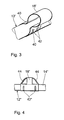
- Figure 4 again shows a short section of an atrial Electrode line 12 "with longitudinal guide 18" attached to it.
- the Longitudinal guide 18 " is designed similarly to the longitudinal guide 18 'from FIG. 3 and, like this, has restraining constrictions 42 "that are generated, for example, by crimping.
- the Longitudinal guide 18 but also two slopes 44, which are in the manner of a Stents are designed like a bridge and are intended to prevent the Longitudinal guides 18 "when inserting the atrial electrode line 12" in Interlocking tissue.
- Figure 5 again shows a short section of an atrial Electrode line 12 "'with longitudinal guide 18' '' arranged thereon the longitudinal guide 18 "'is preferably made of metal such as Nitinol is formed and has to hold and guide along one ventricular electrode line two brackets 50.
- the Longitudinal guide 18 '' 'on two tongues 52 which surround the atrial electrode line 12 '' 'are molded around and are circumferential to the atrial Electrode line 12 "'overlap.
- the tongues 52 have one Function, the longitudinal guide 18 "'hold on the atrial lead 12' '' to give, by developing a corresponding bracket effect.
- the thickness of the tongues 52 ensures that one in the Longitudinal guide 18 '' 'located ventricular electrode line a distance from the atrial lead 12 '' '. Therefore, at Longitudinal guide 18 '' 'such constrictions as the constrictions 40 of the Longitudinal guide 18 'from Figure 3 are omitted.
- Figure 6 shows the distal end of an atrial electrode lead 12 '' '. With a longitudinal guide 18 "', as already described in Figure 5. From Figure 6 shows that the tip electrode 24 '' 'and the ring electrode 26 '' 'on the circumferential side of the atrial electrode catheter 12' '' are isolated when implanting a ventricular lead is facing and is led past this. This circumferential direction is determined by the orientation of the longitudinal guide 18 '' '.
- a cable 60 which within the ventricular lead and at its distal end exit.
- This cable is with the distal end of the atrial Electrode lead connected so that it is possible to connect the distal end of the atrial lead with the help of the cable in the direction of the distal Pull the end of the ventricular lead.
- the cable pull runs this purpose within the ventricular lead up to proximal end to be operated from there.
- the eyelet can be opposite the longitudinal axis the atrial lead, e.g. tilted by means of a cable that there is a jamming of the eyelet with one in the eyelet located ventricular lead comes, so both Electrode lines are fixed relative to each other.
- the eyelet on the atrial lead can also be used be otherwise deformable to prevent jamming with a Allow electrode lead in the eyelet.
- the atrial lead in the area of the eyelet e.g. S-shaped or otherwise bent to preform such that the Longitudinal axes of the atrial lead and ventricular Electrode leads in the area of the eye tend not to be parallel to run to each other so that there is tension between the eyelet and the second electrode line located in it comes.
- the first atrial lead is then inserted Preforming e.g. canceled by means of an appropriate stylet, see above that atrial and ventricular lead are slightly relative to each other are longitudinally displaceable.
- the atrial electrode lead also tilts the eyelet due to its preforming the ventricular lead and the two lead fixed relative to each other.
Abstract
Description
Die Erfindung betrifft eine intravaskuläre Elektrodenanordnung umfassend eine erste und zweite, für das Platzieren in Blutgefäßen wie Venen oder Arterien angepasste Elektrodenleitung mit jeweils einer Stimulationsund/oder Sensing-Elektrode im Bereich eines distalen Endes der jeweiligen Elektrodenleitung.The invention relates to an intravascular electrode arrangement comprising a first and second, for placement in blood vessels such as veins or Electrode line adapted to arteries, each with a stimulation and / or Sensing electrode in the area of a distal end of the respective Electrode line.
Im Sinne der vorliegenden Erfindung wird zwischen intrakardialen Elektrodenleitungen einerseits und intravaskulären Elektrodenleitungen in dem Sinne unterschieden, dass intrakardiale Elektrodenleitungen dazu ausgebildet sind, dass ihre Sensing- oder Stimulationselektroden nach der Implantation im Atrium oder Ventrikel eines Herzens platziert sind, während intravaskuläre Elektrodenleitungen im hier verstandenen engeren Sinne solche Elektrodenleitungen sind, deren Elektroden sich nach der Implantation in einer Ader wie beispielsweise einer Vene oder einer Arterie befinden. Aufgrund der räumlichen Enge, die in solchen Blutgefäßen herrscht, sind die entsprechenden intravaskulären Implantationsorte schwieriger anzusteuern, als intrakardiale Implantationsorte. Außerdem variieren die intravaskulären Implantationsorte von Patient zu Patient stärker, als dies bei intrakardialen Implantationsorten der Fall ist.For the purposes of the present invention, intracardiac Electrode leads on the one hand and intravascular electrode leads in distinguished the sense that intracardiac lead leads to it are designed that their sensing or stimulation electrodes after the Are placed during the implantation in the atrium or ventricle of a heart intravascular electrode leads in the narrower sense understood here are such electrode lines, whose electrodes are after the Implantation in a vein such as a vein or an artery are located. Because of the spatial constriction that occurs in such blood vessels prevails, the corresponding intravascular implantation sites more difficult to control than intracardiac implantation sites. Moreover The intravascular implantation locations vary from patient to patient stronger than is the case with intracardial implantation sites.
Im Zusammenhang mit der Stimulation eines Herzens stellt die Stimulation des linken Herzens deshalb ein Problem dar, weil eine Platzierung intrakardialer Elektroden im linken Herzen höchst aufwendig ist. Daher werden zur Stimulation des linken Atriums oder Ventrikels statt dessen intravaskuläre Elektroden verwendet, die beispielsweise in Herzkranzgefäße eingeführt werden. Damit ergibt sich das im vorangegangenen Absatz geschilderte Problem.In connection with the stimulation of a heart, the stimulation represents of the left heart is a problem because of placement intracardiac electrodes in the left heart is extremely complex. Therefore are used to stimulate the left atrium or ventricle instead intravascular electrodes used, for example in Coronary arteries are introduced. This results in problem described in the previous paragraph.
Dieses Problem wird erfindungsgemäß durch eine intravaskuläre Elektrodenanordnung der eingangs genannten Art gelöst, bei der außen an der ersten Elektrodenleitung angebrachte Längsführungen zur Aufnahme der zweiten Elektrodenleitung vorgesehen sind.According to the invention, this problem is solved by an intravascular Electrode arrangement of the type mentioned solved at the outside longitudinal guides attached to the first electrode line for receiving the second electrode line are provided.
Dieser Lösung liegt der Gedanke zugrunde, für das linke Atrium und den linken Ventrikel eines Herzens jeweils einen eigenen intravaskulären Elektrodenkatheter vorzusehen, die jeweils hinsichtlich der unterschiedlichen Implantationsorte optimal gestaltet sind. Bevorzugt ist in diesem Zusammenhang eine Elektrodenanordnung, bei der die erste Elektrodenleitung mit den Längsführungen als atrialer Elektrodenkatheter ausgebildet ist, während die zweite Elektrodenleitung der Führung der ersten, ventrikulären Elektrodenleitung dient und als ventrikulärer Elektrodenkatheter ausgebildet ist. Zur Implantation dieser Elektrodenleitungen wird zunächst die ventrikuläre Elektrodenleitung eingeführt. Dies ist einfach auf übliche weise möglich, da die ventrikuläre Elektrodenleitung keine Führungen aufweist. Anschließend wird die atriale Elektrodenleitung mit ihren Führungen so über die ventrikuläre Elektrodenleitung geschoben, dass die ventrikuläre elektrodenleitung innerhalb der Längsführungen verläuft. Die atriale Elektrodenleitung mit ihren Führungen kann dann vorgeschoben werden, wobei sie durch die ventrikuläre Elektrodenleitung geführt wird.This solution is based on the idea for the left atrium and the left ventricle of a heart each has its own intravascular Provide electrode catheters, each with respect to the different implantation locations are optimally designed. Is preferred in in this connection an electrode arrangement in which the first Electrode lead with the longitudinal guides as an atrial electrode catheter is formed while the second electrode line is guiding the serves first, ventricular lead and as ventricular Electrode catheter is formed. To implant this Electrode lines become the ventricular electrode line introduced. This is easily possible in the usual way, since the ventricular Electrode line has no guides. Then the atrial Electrode lead with its guides over the ventricular Electrode line pushed that the ventricular electrode line runs within the longitudinal guides. The atrial lead with their guides can then be advanced, passing through the ventricular lead is guided.
Um eine möglichst präzise Führung der ersten Elektrodenleitung zu ermöglichen, weisen die Längsführungen Ösen auf, die über die zweite Elektrodenleitung zu schieben und dementsprechend bezüglich ihres Innendurchmessers an den Außendurchmesser der zweiten Elektrodenleitung angepasst sind und diesem im wesentlichen entsprechen.In order to guide the first electrode line as precisely as possible allow, the longitudinal guides have eyelets that over the second Slide electrode lead and accordingly with respect to your Inner diameter to the outer diameter of the second Electrode line are adapted and this essentially correspond.
Der Durchmesser der beiden Elektrodenleitungen ist vorzugsweise geringer als 2mm, damit sie als intravaskuläre Elektrodenleitungen eingesetzt werden können.The diameter of the two electrode lines is preferred less than 2mm so they can be used as intravascular electrode leads can be used.
Um eine zwei Elektrodenleitungen umfassende Elektrodenanordnung der vorgenannten Art zu ermöglichen, ist in erster Linie nur eine der beiden Elektrodenleitung im erfindungsgemäßen Sinne gegenüber dem Stand der Technik abzuwandeln, während die zweite Elektrodenleitung dem Stand der Technik entsprechen kann. Dementsprechend besteht die erfindungsgemäße Lösung des eingangs genannten Problems bereits in einer einzigen, erfindungsgemäß gestalteten Elektrodenleitung mit außen an der Elektrodenleitung angebrachten Längsführungen, welche vorzugsweise Ösen umfassen.Around an electrode arrangement comprising two electrode lines To enable the aforementioned type is primarily only one of the two Electrode line in the sense of the invention compared to the prior art Modify technology while the second electrode line is standing can correspond to the technology. Accordingly, there is solution according to the invention of the problem mentioned at the beginning in a single, according to the invention designed electrode line with the outside longitudinal guides attached to the electrode line, which preferably comprise eyelets.
Die Längsführungen enthalten vorzugsweise Nitinol, eine Nickel-Titanlegierung.The longitudinal guides preferably contain nitinol, a nickel-titanium alloy.
Die Längsführungen weisen in Längsrichtung der Elektrodenleitung zwei Enden auf, von denen vorzugsweise zumindest eines der Enden eine Schräge aufweist, die ausgehend von der Elektrodenleitung zu dem jeweils anderen Ende hin geneigt ist. Besonders bevorzugt ist eine Variante, bei der beide Enden der Längsführungen entsprechend abgeschrägt sind. Eine derartige Schräge erleichtert das Einführen der Elektrodenleitung bzw. der Elektrodenanordnung. The longitudinal guides have two in the longitudinal direction of the electrode line Ends, of which preferably at least one of the ends is one Inclined, starting from the electrode line to each other end is inclined. A variant is particularly preferred which both ends of the longitudinal guides are bevelled accordingly. A such a slope facilitates the insertion of the electrode line or Electrode assembly.
In einer bevorzugten Ausführungsvariante ist die Schräge der Längsführungen von einer offenen Gitterstruktur oder einem Drahtgeflecht gebildet. Diese Gitterstruktur oder das Drahtgeflecht ist insbesondere nach Art eines Stents ausgestaltet.In a preferred embodiment, the slope is Longitudinal guides of an open lattice structure or a wire mesh educated. This lattice structure or the wire mesh is especially after Designed like a stent.
Bevorzugt wird auch eine Elektrodenleitung, bei der die Längsführungen auf eine Hülle der Elektrodenleitung nachträglich aufgebracht sind. Die Alternative hierzu besteht in Längsführungen, die von dem Hüllenmaterial selbst gebildet sind, so dass Längsführungen und die Hülle der Elektrodenleitung zusammen einteilig ausgebildet sind. Bei der bevorzugten Variante enthalten die Hülle der Elektrodenleitung und die Längsführungen unterschiedliches Material, beispielsweise ist die Hülle der Elektrodenleitung von silikonhaltigem Material gebildet, während die Längsführungen im wesentlichen von nitinolhaltigem Material, also einem Metall, gebildet sind.An electrode line in which the longitudinal guides are also preferred are subsequently applied to a sheath of the electrode line. The An alternative to this is in longitudinal guides made of the casing material themselves are formed, so that longitudinal guides and the shell of the Electrode line are integrally formed together. In the preferred variant contain the sheath of the electrode line and Longitudinal guides different material, for example, the shell of the Electrode lead formed from silicon-containing material while the Longitudinal guides essentially of nitinol-containing material, i.e. one Metal.
In einer bevorzugten Ausführungsvariante weisen die Längsführungen reibungsvermindernde Zungen auf, die zwischen einem zur Aufnahme der zweiten Elektrodenleitung vorgesehenen Hohlraum der Längsführungen und der Hülle der ersten Elektrodenleitung angeordnet und derart ausgebildet sind, dass eine Hülle der zweiten Elektrodenleitung vermittels der Zungen einen Abstand zu der Hülle der ersten Elektrodenleitung hat. Mit diesen Abstand herstellenden Zungen kann die unmittelbare Reibung der Hüllen der beiden Elektrodenleitungen aneinander weitgehend vermieden werden, so dass sich die beiden Elektrodenleitungen möglichst leichtgängig relativ zueinander längsverschieben lassen. Mit Zunge ist in diesem Zusammenhang jede Art abstandsvermittelnder Bestandteil der Längsführungen gemeint, insbesondere metallhaltige Bestandteile der Längsführung, die innerhalb der Längsführungen zwischen den beiden Elektrodenleitungen angeordnet sind.In a preferred embodiment variant, the longitudinal guides have friction-reducing tongues on between which to hold the second electrode line provided cavity of the longitudinal guides and the sheath of the first electrode line arranged and such are formed so that a sheath of the second electrode line the tongues is at a distance from the sheath of the first electrode line. With these spacing tongues, the immediate friction can the shells of the two electrode lines to each other largely be avoided so that the two electrode lines are as possible can be easily moved longitudinally relative to each other. With tongue is in In this connection, every type of distance - imparting component of the Longitudinal guides meant, especially metal-containing components of the Longitudinal guide that is within the longitudinal guides between the two Electrode lines are arranged.
Um schließlich einen Kurzschluss oder elektrischen Kontakt der Sensingoder Stimulationselektroden der einen Elektrodenleitung zu den Elektroden der zweiten Elektrodenleitung zu verhindern, ist es vorgesehen, insbesondere die Elektroden der ersten Elektrodenleitung auf derjenigen Seite des Umfangs der ersten Elektrodenleitung elektrisch zu isolieren, die aufgrund der Längsführungen der zweiten Elektrodenleitung zugewandt ist.Finally, a short circuit or electrical contact of the sensing or Stimulation electrodes of the one electrode lead to the electrodes to prevent the second electrode line, it is provided in particular the electrodes of the first electrode line on that To electrically isolate the side of the circumference of the first electrode line, the is facing due to the longitudinal guides of the second electrode line.
Die Erfindung soll nun anhand von Ausführungsbeispielen mit Hilfe der Figuren näher erläutert werden. Die Figuren zeigen:
- Figur 1
- eine Seitenansicht einer Elektrodenanordnung mit zwei Elektrodenleitungen;
- Figur 2
- den in Figur 1 eingetragenen Schnitt A-A in vergrößerter Darstellung;
- Figur 3
- einen Abschnitt einer ersten Elektrodenleitung mit einer Längsführung in Form einer Nitinolhülse;
- Figur 4
- eine Seitenansicht eines Abschnitts einer ersten Elektrodenleitung mit einer Längsführung, die Schrägen aufweist;
- Figur 5
- einen Abschnitt einer Elektrodenleitung mit einer Variante einer Längsführung, die abstandsvermittelnde Zungen aufweist;
- Figur 6
- das distale Ende einer ersten Elektrodenleitung mit teilweise isolierten Stimulations- oder Sensing-Elektroden; und
- Figur 7
- eine alternative Ausführungsform ähnlich Figur 1.
- Figure 1
- a side view of an electrode arrangement with two electrode lines;
- Figure 2
- the section AA entered in Figure 1 in an enlarged view;
- Figure 3
- a section of a first electrode line with a longitudinal guide in the form of a nitinol sleeve;
- Figure 4
- a side view of a portion of a first electrode line with a longitudinal guide which has slopes;
- Figure 5
- a section of an electrode line with a variant of a longitudinal guide which has distance-imparting tongues;
- Figure 6
- the distal end of a first electrode lead with partially isolated stimulation or sensing electrodes; and
- Figure 7
- an alternative embodiment similar to Figure 1.
Figur 1 zeigt eine Elektrodenanordnung 10 mit einem atrialen
Elektrodenkatheter 12 und einem zweiten ventrikulären Elektrodenkatheter
14. Die beiden Elektrodenkatheter 12 und 14 sind aufgrund ihres
Durchmessers und ihrer Flexibilität für eine intravaskuläre Anordnung
geeignet ausgebildet. Das heißt die beiden intravaskulären
Elektrodenkatheter 12 und 14 sind dünn und flexibel genug, um in einem
Blutgefäß wie einer Vene oder Arterie platziert zu werden. FIG. 1 shows an
Beide Elektrodenkatheter 12 und 14 weisen eine Hülle auf, von denen die
Hülle 16 des atrialen Elektrodenkatheters 12 mit Längsführungen 18 in
Form von Ösen ausgestattet ist, die zur längsverschieblichen Aufnahme
des ventrikulären Elektrodenkatheters 14 ausgebildet sind. Ein geeignetes
Material für die Hüllen der Elektrodenkatheter sowie für die
Längsführungen 18 ist beispielsweise Silikon, welches im Bereich der
Längsführungen 18 beispielsweise durch eine Versteifung aus Draht oder
Ähnlichem verstärkt sein kann.Both
Beide Elektrodenkatheter 12 und 14 weisen an Ihrem jeweiligen distalen
Ende Stimulations- und/oder Sensing-Elektroden auf. Die Stimulations- und
Sensing-Elektroden 20 und 22 des ventrikulären Elektrodenkatheters 14
sind dabei in üblicher Weise als Spitzenelektrode 20 und als Ringelektrode
22 ausgebildet. Entsprechende Elektroden ermöglichen wahlweise das
unipolare oder bipolare Stimulieren oder Abfühlen. Alternativ können beide
Elektrodenkatheter auch nur mit einer Elektrode in Form einer Spitzenoder
Ringelektrode ausgestattet sein.Both
Auch der atriale Elektrodenkatheter 12 weist eine Spitzenelektrode 24 und
eine Ringelektrode 26 auf, wobei diese beiden Elektroden auf ihrer der
ventrikulären Elektrodenleitung 14 zugewandten Seite elektrisch isoliert
sind, damit es nicht zu einem Kurzschluss zwischen den Elektroden 20 und
22 des ventrikulären Elektrodenkatheters 14 und den entsprechenden
Elektroden 24 und 26 des atrialen Elektrodenkatheters 12 kommt, falls sich
die distalen Enden der beiden Elektrodenkatheter beim Längsverschieben
des atrialen Elektrodenkatheters bezüglich des ventrikulären
Elektrodenkatheters 12 auf gleicher Höhe befinden.The
Im Falle der Implantation wird zunächst die ventrikuläre Elektrodenleitung
so in Blutgefäße eines Patienten eingeführt, dass das distale Ende der
Elektrodenleitung 14 mit ihren Elektroden 20 und 22 den gewünschten
Zielort, z.B. im Coronar-Sinus einnimmt. Anschließend werden die Ösen 18
der atrialen Elektrodenleitung 12 am proximalen Ende der ventrikulären
Elektrodenleitung 14 auf die Elektrodenleitung 14 geschoben, so dass die
atriale Elektrodenleitung mittels ihrer Ösen 18 von der bereits implantierten
ventrikulären Elektrodenleitung 14 geführt wird. Hat auch das distale Ende
der atrialen Elektrodenleitung 12 den bestimmungsgemäßen Zielort im
Atrium des Herzen erreicht, wird die atriale Elektrodenleitung 12 mittels
ihrer Ösen 18 gegenüber der ventrikulären Elektrodenleitung 14 durch
Verklemmen fixiert. Entsprechende Ösen 18, die ein solches Verklemmen
ermöglichen, sind in Figur 7 dargestellt.In the case of implantation, the ventricular lead is first
inserted into a patient's blood vessels so that the distal end of the
Figur 2 zeigt einen Schnitt durch die Elektrodenanordnung aus Figur 1 im
Bereich einer der Längsführungen 18. Wie Figur 2 zu nehmen ist, ist die
Längsführung 18 ein Bestandteil der Hülle 16 der atrialen Elektrodenleitung
12. Innerhalb dieser Hülle 16 der atrialen Elektrodenleitung 12 ist eine
versteifende Helixwendel 30 aus Metall angeordnet.FIG. 2 shows a section through the electrode arrangement from FIG
Area of one of the longitudinal guides 18. As can be seen in FIG
Longitudinal guide 18 is a component of the
Die ventrikuläre Elektrodenleitung 14 ist ähnlich aufgebaut wie die atriale
Elektronenleitung 12, nur dass sie keine Längsführungen 18 aufweist. Auch
die ventrikuläre Elektrodenleitung 14 weist eine Hülle 32 beispielsweise aus
Silikon und eine darin angeordnete versteifende Metallwendel 34 auf. Der
Außendurchmesser der Hülle 32 ist etwas geringer als der
Innendurchmesser der Längsführung 18, um eine Beweglichkeit der
atrialen Elektrodenleitung 12 bezüglich der ventrikulären Elektrodenleitung
14 zu erlauben.The
Die Längsführung 18 ist so ausgebildet, dass die Hüllen 16 und 32 der
atrialen bzw. ventrikulären der Elektrodenleitung 12 bzw. 14 einen Abstand
a voneinander haben, wie dies durch die gestrichelte Linie 36 in Figur 2
angedeutet ist.The
Figur 3 zeigt einen kurzen Abschnitt einer atrialen Elektrodenleitung 12' mit
einer alternativen Längsführung 18', die als Metallhülse außen auf die
Elektrodenleitung 12' aufgesetzt ist. Die Gestaltung der Metallhülse 18 mit
Einschnürungen 40 ist so gewählt, dass eine in die Metallhülse 18'
eingeführte ventrikuläre Elektrodenleitung einen seitlichen Abstand zur
atrialen Elektrodenleitung 12' einnimmt. Durch Crimpen erzeugte
Einschnürungen 42 an der Metallhülse 18' sorgen für einen sicheren Halt
auf der atrialen Elektrodenleitungen 12'. FIG. 3 shows a short section of an atrial electrode line 12 '
an alternative longitudinal guide 18 ', the outside of the metal sleeve on the
Electrode line 12 'is placed. The design of the
Figur 4 zeigt wiederum einen kurzen Abschnitt einer atrialen
Elektrodenleitung 12" mit drauf angebrachter Längsführung 18". Die
Längsführung 18" ist ähnlich gestaltet wie die Längsführung 18' aus Figur 3
und weist wie diese haltbringende Einschnürungen 42" auf, die
beispielsweise durch Crimpen erzeugt sind. Zusätzlich weist die
Längsführung 18" jedoch auch zwei Schrägen 44 auf, die nach Art eines
Stents stegartig ausgebildet sind und verhindern sollen, dass sich die
Längsführungen 18" beim Einführen der atrialen Elektrodenleitung 12" im
Gewebe verhaken.Figure 4 again shows a short section of an
Figur 5 zeigt wiederum einen kurzen Abschnitt einer atrialen
Elektrodenleitung 12"' mit darauf angeordneter Längsführung 18'''. Auch
die Längsführung 18"' ist vorzugsweise aus Metall wie beispielsweise
Nitinol gebildet und weist zum Halten und für die Führung entlang einer
ventrikulären Elektrodenleitung zwei Bügel 50 auf. Außerdem weist die
Längsführung 18''' zwei Zungen 52 auf, die um die atriale Elektrodenleitung
12''' herumgeformt sind und sich in Umfangsrichtung der atrialen
Elektrodenleitung 12"' überlappen. Die Zungen 52 haben zum einen die
Funktion, der Längsführung 18"' Halt auf der atrialen Elektrodenleitung 12'''
zu geben, indem sie eine entsprechende Klammerwirkung entfalten.
Außerdem sorgt die Dicke der Zungen 52 dafür, dass eine in der
Längsführung 18''' befindliche ventrikuläre Elektrodenleitung einen Abstand
von der atrialen Elektrodenleitung 12''' hat. Daher können bei der
Längsführung 18''' solche Einschnürungen wie die Einschnürungen 40 der
Längsführung 18' aus Figur 3 entfallen.Figure 5 again shows a short section of an
Figur 6 zeigt das distale Ende einer atrialen Elektrodenleitung 12'''. mit
einer Längsführung 18"', wie sie bereits in Figur 5 beschrieben ist. Aus
Figur 6 geht hervor, dass die Spitzenelektrode 24''' und die Ringelektrode
26''' auf derjenigen Umfangsseite des atrialen Elektrodenkatheters 12'''
isoliert sind, die beim Implantieren einer ventrikulären Elektrodenleitung
zugewandt ist und an dieser vorbeigeführt wird. Diese Umfangsrichtung
wird durch die Ausrichtung der Längsführung 18''' bestimmt. Die
Ausrichtung der Längsführung 18''' bezüglich der atrialen Elektrodenleitung
12''' mit ihren teilweise isolierten Elektroden 24''' und 26''' ist somit so zu
wählen, dass die Bügel 50 die Längsführung 18''' in diejenige
Umfangsrichtung weisen, in der die Elektroden 24''' und 26''' der atrialen
Elektrodenleitung 12''' isoliert sind.Figure 6 shows the distal end of an atrial electrode lead 12 '' '. With
a
Gemäß der in Figur 7 abgebildeten Variante ist gegenüber der in Figur 1
dargestellten Variante zusätzlich ein Seilzug 60 vorgesehen, der innerhalb
der ventrikulären Elektrodenleitung verläuft und an deren distalem Ende
austritt. Dieser Seilzug ist mit dem distalen Ende der atrialen
Elektrodenleitung verbunden, so dass es möglich ist, das distale Ende der
atrialen Elektrodenleitung mit Hilfe des Seilzuges in Richtung des distalen
Ende der ventrikulären Elektrodenleitung zu Ziehen. Der Seilzug verlauft zu
diesem Zweck innerhalb der ventrikulären Elektrodenleitung bis zu deren
proximalem Ende, um von dort aus betätigt zu werden.According to the variant shown in FIG. 7, compared to that in FIG
variant additionally provided a
In einer nicht dargestellten Variante einer atrialen Elektrodenleitung mit einer Längsführung bzw. Öse, kann die Öse gegenüber der Längsachse der atrialen Elektrodenleitung z.B. mittels eines Seilzuges so gekippt werden, dass es zu einem Verklemmen der Öse mit einer in der Öse befindlichen ventrikulären Elektrodenleitung kommt, so dass beiden Elektrodenleitungen relativ zueinander fixiert sind.In a variant, not shown, of an atrial electrode line a longitudinal guide or eyelet, the eyelet can be opposite the longitudinal axis the atrial lead, e.g. tilted by means of a cable that there is a jamming of the eyelet with one in the eyelet located ventricular lead comes, so both Electrode lines are fixed relative to each other.
Alternativ hierzu kann die Öse an der atrialen Elektrodenleitung auch anderweitig verformbar ausgebildet sein, um ein Verklemmen mit einer Elektrodenleitung in der Öse zu ermöglichen.Alternatively, the eyelet on the atrial lead can also be used be otherwise deformable to prevent jamming with a Allow electrode lead in the eyelet.
Außerdem ist es möglich, die atriale Elektrodenleitung im Bereich der Öse z.B. S-förmig oder anderweitig gebogen derart vorzuformen, dass die Längsachsen der atrialen Elektrodenleitung und der ventrikulären Elektrodenleitung im Bereich der Öse dazu neigen, nicht parallel zueinander zu verlaufen, so dass es zu Verspannungen zwischen der Öse und der in ihr befindlichen zweiten Elektrodenleitung kommt. Während des Einführens der ersten, atrialen Elektrodenleitung wird dann deren Vorformung z.B. mittels eines entsprechenden Mandrins aufgehoben, so dass atriale und ventrikuläre Elektrodenleitung leicht relativ zueinander längsverschieblich sind. Anschließend - wenn die atriale Elektrodenleitung die vorgesehene Position eingenommen hat - wird der Mandrin entfernt, die atriale Elektrodenleitung verkantet aufgrund ihrer Vorformung die Öse mit der ventrikulären Elektrodenleitung und die beiden Elektrodenleitung sind relativ zueinander fixiert.It is also possible to place the atrial lead in the area of the eyelet e.g. S-shaped or otherwise bent to preform such that the Longitudinal axes of the atrial lead and ventricular Electrode leads in the area of the eye tend not to be parallel to run to each other so that there is tension between the eyelet and the second electrode line located in it comes. During the The first atrial lead is then inserted Preforming e.g. canceled by means of an appropriate stylet, see above that atrial and ventricular lead are slightly relative to each other are longitudinally displaceable. Then - if the atrial lead has taken the intended position - the stylet is removed, the atrial electrode lead also tilts the eyelet due to its preforming the ventricular lead and the two lead fixed relative to each other.
Claims (16)
Applications Claiming Priority (2)
| Application Number | Priority Date | Filing Date | Title |
|---|---|---|---|
| DE10153842 | 2001-10-24 | ||
| DE10153842A DE10153842A1 (en) | 2001-10-24 | 2001-10-24 | electrode assembly |
Publications (2)
| Publication Number | Publication Date |
|---|---|
| EP1306103A1 true EP1306103A1 (en) | 2003-05-02 |
| EP1306103B1 EP1306103B1 (en) | 2005-10-19 |
Family
ID=7704395
Family Applications (1)
| Application Number | Title | Priority Date | Filing Date |
|---|---|---|---|
| EP02090354A Expired - Lifetime EP1306103B1 (en) | 2001-10-24 | 2002-10-15 | Electrode assembly |
Country Status (4)
| Country | Link |
|---|---|
| US (1) | US7561924B2 (en) |
| EP (1) | EP1306103B1 (en) |
| AT (1) | ATE306964T1 (en) |
| DE (2) | DE10153842A1 (en) |
Cited By (1)
| Publication number | Priority date | Publication date | Assignee | Title |
|---|---|---|---|---|
| EP2459274A2 (en) * | 2009-07-30 | 2012-06-06 | Richard North | Modular electrode and insertion tool |
Families Citing this family (15)
| Publication number | Priority date | Publication date | Assignee | Title |
|---|---|---|---|---|
| US8239045B2 (en) | 2003-06-04 | 2012-08-07 | Synecor Llc | Device and method for retaining a medical device within a vessel |
| US7617007B2 (en) * | 2003-06-04 | 2009-11-10 | Synecor Llc | Method and apparatus for retaining medical implants within body vessels |
| US7082336B2 (en) | 2003-06-04 | 2006-07-25 | Synecor, Llc | Implantable intravascular device for defibrillation and/or pacing |
| JP4616252B2 (en) * | 2003-06-04 | 2011-01-19 | シネコー・エルエルシー | Intravascular electrophysiology system and method |
| WO2005058415A2 (en) * | 2003-12-12 | 2005-06-30 | Synecor, Llc | Implantable medical device having pre-implant exoskeleton |
| WO2005077450A2 (en) * | 2004-02-10 | 2005-08-25 | Synecor, Llc | Intravascular delivery system for therapeutic agents |
| US7590454B2 (en) * | 2004-03-12 | 2009-09-15 | Boston Scientific Neuromodulation Corporation | Modular stimulation lead network |
| US20050203600A1 (en) * | 2004-03-12 | 2005-09-15 | Scimed Life Systems, Inc. | Collapsible/expandable tubular electrode leads |
| US8412348B2 (en) | 2004-05-06 | 2013-04-02 | Boston Scientific Neuromodulation Corporation | Intravascular self-anchoring integrated tubular electrode body |
| US7937160B2 (en) | 2004-12-10 | 2011-05-03 | Boston Scientific Neuromodulation Corporation | Methods for delivering cortical electrode leads into patient's head |
| US20110009933A1 (en) * | 2009-07-09 | 2011-01-13 | Boston Scientific Neuromodulation Corporation | Piggy-back percutaneous lead insertion kit |
| US20130259357A1 (en) * | 2012-01-18 | 2013-10-03 | Cachet Financial Solutions Inc. | Remote deposit capture method and apparatus |
| US10098768B2 (en) * | 2014-09-15 | 2018-10-16 | Cook Medical Technologies Llc | Ratchet operated vascular intervention device delivery system |
| DE102018113593A1 (en) * | 2018-06-07 | 2019-12-12 | Biotronik Se & Co. Kg | Electrode cable with variable, stepwise adjustable fixation length |
| DE102018113594A1 (en) | 2018-06-07 | 2019-12-12 | Biotronik Se & Co. Kg | Electrode cable with variable, stepless fixation length |
Citations (5)
| Publication number | Priority date | Publication date | Assignee | Title |
|---|---|---|---|---|
| DE2605590A1 (en) * | 1976-02-12 | 1977-08-18 | Heinz Dr Med Praeuer | Pacemaker electrode with flexible electrode catheter - with flexible projecting base for abutment against wall of heart |
| US5267958A (en) * | 1992-03-30 | 1993-12-07 | Medtronic, Inc. | Exchange catheter having exterior guide wire loops |
| US6056722A (en) * | 1997-09-18 | 2000-05-02 | Iowa-India Investments Company Limited Of Douglas | Delivery mechanism for balloons, drugs, stents and other physical/mechanical agents and methods of use |
| US6095990A (en) * | 1998-08-31 | 2000-08-01 | Parodi; Juan Carlos | Guiding device and method for inserting and advancing catheters and guidewires into a vessel of a patient in endovascular treatments |
| WO2001068177A1 (en) * | 2000-03-10 | 2001-09-20 | Kensey Nash Corporation | Device for connecting a catheter onto a guide-wire |
Family Cites Families (18)
| Publication number | Priority date | Publication date | Assignee | Title |
|---|---|---|---|---|
| US7205A (en) * | 1850-03-26 | Apparatus foe receiving and transferring to the pile sheets of paper | ||
| US4402329A (en) * | 1981-09-28 | 1983-09-06 | Medtronic, Inc. | Positive anchoring A-V lead |
| US4479500A (en) | 1982-09-16 | 1984-10-30 | Medtronic, Inc. | Pacing lead with A-V distance adapter |
| US4904431A (en) * | 1988-08-12 | 1990-02-27 | Baxter International, Inc. | Process for manufacturing catheters |
| US5107856A (en) * | 1991-01-10 | 1992-04-28 | Siemens-Pacesetter, Inc. | Multiple lead suture sleeve |
| US5706809A (en) * | 1993-01-29 | 1998-01-13 | Cardima, Inc. | Method and system for using multiple intravascular sensing devices to detect electrical activity |
| US5908446A (en) * | 1994-07-07 | 1999-06-01 | Cardiac Pathways Corporation | Catheter assembly, catheter and multi-port introducer for use therewith |
| DE4425195C1 (en) | 1994-07-16 | 1995-11-16 | Osypka Peter | Heart catheter with multiple electrode device |
| US5674274A (en) * | 1995-12-14 | 1997-10-07 | Pacesetter, Inc. | Implantable adjustable single-pass A-V lead for use with an implantable stimulation device |
| US5954761A (en) * | 1997-03-25 | 1999-09-21 | Intermedics Inc. | Implantable endocardial lead assembly having a stent |
| US5957967A (en) | 1998-02-19 | 1999-09-28 | Medtronic, Inc. | Implantable medical lead using stamped conductor and distal loop |
| US6132456A (en) * | 1998-03-10 | 2000-10-17 | Medtronic, Inc. | Arrangement for implanting an endocardial cardiac lead |
| US5902331A (en) * | 1998-03-10 | 1999-05-11 | Medtronic, Inc. | Arrangement for implanting an endocardial cardiac lead |
| US6094596A (en) * | 1998-06-19 | 2000-07-25 | Angeron Corporation | Transvenous defibrillation lead system for use in middle cardiac vein |
| US6129749A (en) | 1998-08-25 | 2000-10-10 | Cardiac Pacemakers, Inc. | Monorail left ventricular access lead |
| EP1106202A3 (en) * | 1999-11-30 | 2004-03-31 | BIOTRONIK Mess- und Therapiegeräte GmbH & Co Ingenieurbüro Berlin | Electrode for intravascular stimulation, cardioversion and /or defibrillation |
| AU2001249877A1 (en) | 2000-04-13 | 2001-10-30 | Uab Research Foundation | Inter-atrial septum electrode for atrial defibrillation |
| US6574512B1 (en) * | 2000-08-28 | 2003-06-03 | Cardiac Pacemakers, Inc. | Lead system with main lead and transverse lead |
-
2001
- 2001-10-24 DE DE10153842A patent/DE10153842A1/en not_active Withdrawn
-
2002
- 2002-10-15 DE DE50204581T patent/DE50204581D1/en not_active Expired - Lifetime
- 2002-10-15 EP EP02090354A patent/EP1306103B1/en not_active Expired - Lifetime
- 2002-10-15 AT AT02090354T patent/ATE306964T1/en not_active IP Right Cessation
- 2002-10-22 US US10/278,040 patent/US7561924B2/en not_active Expired - Fee Related
Patent Citations (5)
| Publication number | Priority date | Publication date | Assignee | Title |
|---|---|---|---|---|
| DE2605590A1 (en) * | 1976-02-12 | 1977-08-18 | Heinz Dr Med Praeuer | Pacemaker electrode with flexible electrode catheter - with flexible projecting base for abutment against wall of heart |
| US5267958A (en) * | 1992-03-30 | 1993-12-07 | Medtronic, Inc. | Exchange catheter having exterior guide wire loops |
| US6056722A (en) * | 1997-09-18 | 2000-05-02 | Iowa-India Investments Company Limited Of Douglas | Delivery mechanism for balloons, drugs, stents and other physical/mechanical agents and methods of use |
| US6095990A (en) * | 1998-08-31 | 2000-08-01 | Parodi; Juan Carlos | Guiding device and method for inserting and advancing catheters and guidewires into a vessel of a patient in endovascular treatments |
| WO2001068177A1 (en) * | 2000-03-10 | 2001-09-20 | Kensey Nash Corporation | Device for connecting a catheter onto a guide-wire |
Cited By (2)
| Publication number | Priority date | Publication date | Assignee | Title |
|---|---|---|---|---|
| EP2459274A2 (en) * | 2009-07-30 | 2012-06-06 | Richard North | Modular electrode and insertion tool |
| EP2459274A4 (en) * | 2009-07-30 | 2014-09-24 | Richard North | Modular electrode and insertion tool |
Also Published As
| Publication number | Publication date |
|---|---|
| US7561924B2 (en) | 2009-07-14 |
| DE10153842A1 (en) | 2003-05-08 |
| US20030097051A1 (en) | 2003-05-22 |
| ATE306964T1 (en) | 2005-11-15 |
| DE50204581D1 (en) | 2005-11-24 |
| EP1306103B1 (en) | 2005-10-19 |
Similar Documents
| Publication | Publication Date | Title |
|---|---|---|
| DE69632006T2 (en) | Guide wire unit | |
| DE69635402T2 (en) | Guide unit with internal guidewire made of a shape memory alloy | |
| EP1306103B1 (en) | Electrode assembly | |
| DE602005002182T2 (en) | Flat wire spiral electrode usable in screw-in cardiac stimulation leads | |
| DE60017716T2 (en) | COEXTRUDED MEDICAL MULTILUMENLINE | |
| DE60023702T2 (en) | SYSTEM FOR INTRODUCING CATHETERS | |
| DE60017962T2 (en) | Clamping device for clamping a line | |
| DE2506694C2 (en) | Implantable, transvenous insertable electrode arrangement | |
| DE60015742T2 (en) | MEDICAL ELECTRODE LINE | |
| DE19957241B4 (en) | Electric cable for medical purposes and system for introducing same | |
| DE69824425T2 (en) | CONNECTION SYSTEM FOR PACING PIPES | |
| DE602004006039T2 (en) | Multifunctional handle for catheters | |
| DE69936786T2 (en) | TEMPORARY ATRIAL ELECTRODE CATHETER FOR CARDIOVERSION | |
| DE60019908T2 (en) | coronary sinus | |
| DE69929963T2 (en) | Medical lead with a sigma feature | |
| DE60129843T2 (en) | GUIDANCE OR DIAGNOSIS CATHETER FOR RIGHT HEART CANCER | |
| DE69627290T2 (en) | Implantable electrode cable with at least one electrode contact | |
| DE69636709T2 (en) | Cardiac lead with insulating composite structure | |
| DE3049652C2 (en) | Endocardial, implantable lead for pacemakers | |
| DE2613044B2 (en) | Implantable electrical lead | |
| DE8207842U1 (en) | IMPLANTABLE LINE | |
| DE3507119A1 (en) | ADJUSTABLE ENDOCARDIAL ELECTRODE ARRANGEMENT | |
| DE10058106A1 (en) | Medical electrical line with in the direction of the distant increasing bending stiffness | |
| DE60016512T2 (en) | Implantable electrode lead | |
| EP0779079B1 (en) | Single electrode lead for double-chamber cardiac stimulators, especially for DD cardiac stimulators |
Legal Events
| Date | Code | Title | Description |
|---|---|---|---|
| PUAI | Public reference made under article 153(3) epc to a published international application that has entered the european phase |
Free format text: ORIGINAL CODE: 0009012 |
|
| AK | Designated contracting states |
Designated state(s): AT BE BG CH CY CZ DE DK EE ES FI FR GB GR IE IT LI LU MC NL PT SE SK TR |
|
| AX | Request for extension of the european patent |
Extension state: AL LT LV MK RO SI |
|
| 17P | Request for examination filed |
Effective date: 20030901 |
|
| AKX | Designation fees paid |
Designated state(s): AT BE BG CH CY CZ DE DK EE ES FI FR GB GR IE IT LI LU MC NL PT SE SK TR |
|
| 17Q | First examination report despatched |
Effective date: 20040716 |
|
| GRAP | Despatch of communication of intention to grant a patent |
Free format text: ORIGINAL CODE: EPIDOSNIGR1 |
|
| GRAS | Grant fee paid |
Free format text: ORIGINAL CODE: EPIDOSNIGR3 |
|
| GRAA | (expected) grant |
Free format text: ORIGINAL CODE: 0009210 |
|
| AK | Designated contracting states |
Kind code of ref document: B1 Designated state(s): AT BE BG CH CY CZ DE DK EE ES FI FR GB GR IE IT LI LU MC NL PT SE SK TR |
|
| PG25 | Lapsed in a contracting state [announced via postgrant information from national office to epo] |
Ref country code: IT Free format text: LAPSE BECAUSE OF FAILURE TO SUBMIT A TRANSLATION OF THE DESCRIPTION OR TO PAY THE FEE WITHIN THE PRE;WARNING: LAPSES OF ITALIAN PATENTS WITH EFFECTIVE DATE BEFORE 2007 MAY HAVE OCCURRED AT ANY TIME BEFORE 2007. THE CORRECT EFFECTIVE DATE MAY BE DIFFERENT FROM THE ONE RECORDED.SCRIBED TIME-LIMIT Effective date: 20051019 Ref country code: IE Free format text: LAPSE BECAUSE OF FAILURE TO SUBMIT A TRANSLATION OF THE DESCRIPTION OR TO PAY THE FEE WITHIN THE PRESCRIBED TIME-LIMIT Effective date: 20051019 Ref country code: FI Free format text: LAPSE BECAUSE OF FAILURE TO SUBMIT A TRANSLATION OF THE DESCRIPTION OR TO PAY THE FEE WITHIN THE PRESCRIBED TIME-LIMIT Effective date: 20051019 Ref country code: SK Free format text: LAPSE BECAUSE OF FAILURE TO SUBMIT A TRANSLATION OF THE DESCRIPTION OR TO PAY THE FEE WITHIN THE PRESCRIBED TIME-LIMIT Effective date: 20051019 Ref country code: CZ Free format text: LAPSE BECAUSE OF FAILURE TO SUBMIT A TRANSLATION OF THE DESCRIPTION OR TO PAY THE FEE WITHIN THE PRESCRIBED TIME-LIMIT Effective date: 20051019 |
|
| REG | Reference to a national code |
Ref country code: GB Ref legal event code: FG4D Free format text: NOT ENGLISH |
|
| REG | Reference to a national code |
Ref country code: CH Ref legal event code: EP Ref country code: CH Ref legal event code: NV Representative=s name: BRAUNPAT BRAUN EDER AG |
|
| GBT | Gb: translation of ep patent filed (gb section 77(6)(a)/1977) | ||
| REG | Reference to a national code |
Ref country code: IE Ref legal event code: FG4D Free format text: LANGUAGE OF EP DOCUMENT: GERMAN |
|
| REF | Corresponds to: |
Ref document number: 50204581 Country of ref document: DE Date of ref document: 20051124 Kind code of ref document: P |
|
| REG | Reference to a national code |
Ref country code: SE Ref legal event code: TRGR |
|
| PG25 | Lapsed in a contracting state [announced via postgrant information from national office to epo] |
Ref country code: DK Free format text: LAPSE BECAUSE OF FAILURE TO SUBMIT A TRANSLATION OF THE DESCRIPTION OR TO PAY THE FEE WITHIN THE PRESCRIBED TIME-LIMIT Effective date: 20060119 Ref country code: BG Free format text: LAPSE BECAUSE OF FAILURE TO SUBMIT A TRANSLATION OF THE DESCRIPTION OR TO PAY THE FEE WITHIN THE PRESCRIBED TIME-LIMIT Effective date: 20060119 Ref country code: GR Free format text: LAPSE BECAUSE OF FAILURE TO SUBMIT A TRANSLATION OF THE DESCRIPTION OR TO PAY THE FEE WITHIN THE PRESCRIBED TIME-LIMIT Effective date: 20060119 |
|
| PG25 | Lapsed in a contracting state [announced via postgrant information from national office to epo] |
Ref country code: ES Free format text: LAPSE BECAUSE OF FAILURE TO SUBMIT A TRANSLATION OF THE DESCRIPTION OR TO PAY THE FEE WITHIN THE PRESCRIBED TIME-LIMIT Effective date: 20060130 |
|
| PG25 | Lapsed in a contracting state [announced via postgrant information from national office to epo] |
Ref country code: PT Free format text: LAPSE BECAUSE OF FAILURE TO SUBMIT A TRANSLATION OF THE DESCRIPTION OR TO PAY THE FEE WITHIN THE PRESCRIBED TIME-LIMIT Effective date: 20060320 |
|
| REG | Reference to a national code |
Ref country code: IE Ref legal event code: FD4D |
|
| ET | Fr: translation filed | ||
| PLBE | No opposition filed within time limit |
Free format text: ORIGINAL CODE: 0009261 |
|
| STAA | Information on the status of an ep patent application or granted ep patent |
Free format text: STATUS: NO OPPOSITION FILED WITHIN TIME LIMIT |
|
| 26N | No opposition filed |
Effective date: 20060720 |
|
| PG25 | Lapsed in a contracting state [announced via postgrant information from national office to epo] |
Ref country code: MC Free format text: LAPSE BECAUSE OF NON-PAYMENT OF DUE FEES Effective date: 20061031 |
|
| BERE | Be: lapsed |
Owner name: BIOTRONIK MESS- UND THERAPIEGERATE G.M.B.H. & CO Effective date: 20061031 |
|
| PG25 | Lapsed in a contracting state [announced via postgrant information from national office to epo] |
Ref country code: AT Free format text: LAPSE BECAUSE OF NON-PAYMENT OF DUE FEES Effective date: 20061015 |
|
| PG25 | Lapsed in a contracting state [announced via postgrant information from national office to epo] |
Ref country code: EE Free format text: LAPSE BECAUSE OF FAILURE TO SUBMIT A TRANSLATION OF THE DESCRIPTION OR TO PAY THE FEE WITHIN THE PRESCRIBED TIME-LIMIT Effective date: 20051019 |
|
| PG25 | Lapsed in a contracting state [announced via postgrant information from national office to epo] |
Ref country code: TR Free format text: LAPSE BECAUSE OF FAILURE TO SUBMIT A TRANSLATION OF THE DESCRIPTION OR TO PAY THE FEE WITHIN THE PRESCRIBED TIME-LIMIT Effective date: 20051019 Ref country code: LU Free format text: LAPSE BECAUSE OF NON-PAYMENT OF DUE FEES Effective date: 20061015 |
|
| PG25 | Lapsed in a contracting state [announced via postgrant information from national office to epo] |
Ref country code: CY Free format text: LAPSE BECAUSE OF FAILURE TO SUBMIT A TRANSLATION OF THE DESCRIPTION OR TO PAY THE FEE WITHIN THE PRESCRIBED TIME-LIMIT Effective date: 20051019 |
|
| PGFP | Annual fee paid to national office [announced via postgrant information from national office to epo] |
Ref country code: NL Payment date: 20081023 Year of fee payment: 7 |
|
| PG25 | Lapsed in a contracting state [announced via postgrant information from national office to epo] |
Ref country code: BE Free format text: LAPSE BECAUSE OF FAILURE TO SUBMIT A TRANSLATION OF THE DESCRIPTION OR TO PAY THE FEE WITHIN THE PRESCRIBED TIME-LIMIT Effective date: 20061031 |
|
| PGFP | Annual fee paid to national office [announced via postgrant information from national office to epo] |
Ref country code: IT Payment date: 20081027 Year of fee payment: 7 |
|
| PGRI | Patent reinstated in contracting state [announced from national office to epo] |
Ref country code: IT Effective date: 20091201 |
|
| REG | Reference to a national code |
Ref country code: NL Ref legal event code: V1 Effective date: 20100501 |
|
| PG25 | Lapsed in a contracting state [announced via postgrant information from national office to epo] |
Ref country code: NL Free format text: LAPSE BECAUSE OF NON-PAYMENT OF DUE FEES Effective date: 20100501 |
|
| PGRI | Patent reinstated in contracting state [announced from national office to epo] |
Ref country code: IT Effective date: 20091201 |
|
| REG | Reference to a national code |
Representative=s name: RANDOLL, SOEREN, DIPL.-CHEM. UNIV. DR. RER. NA, DE Ref country code: DE Ref legal event code: R082 Ref document number: 50204581 Country of ref document: DE |
|
| REG | Reference to a national code |
Ref country code: DE Ref legal event code: R081 Ref document number: 50204581 Country of ref document: DE Owner name: BIOTRONIK SE & CO. KG, DE Free format text: FORMER OWNER: BIOTRONIK MESS- UND THERAPIEGERAETE GMBH & CO. INGENIEURBUERO BERLIN, 12359 BERLIN, DE Effective date: 20111219 |
|
| PGFP | Annual fee paid to national office [announced via postgrant information from national office to epo] |
Ref country code: FR Payment date: 20121113 Year of fee payment: 11 |
|
| PGFP | Annual fee paid to national office [announced via postgrant information from national office to epo] |
Ref country code: GB Payment date: 20121023 Year of fee payment: 11 Ref country code: SE Payment date: 20121024 Year of fee payment: 11 |
|
| REG | Reference to a national code |
Ref country code: SE Ref legal event code: EUG |
|
| GBPC | Gb: european patent ceased through non-payment of renewal fee |
Effective date: 20131015 |
|
| PG25 | Lapsed in a contracting state [announced via postgrant information from national office to epo] |
Ref country code: GB Free format text: LAPSE BECAUSE OF NON-PAYMENT OF DUE FEES Effective date: 20131015 |
|
| REG | Reference to a national code |
Ref country code: FR Ref legal event code: ST Effective date: 20140630 |
|
| PG25 | Lapsed in a contracting state [announced via postgrant information from national office to epo] |
Ref country code: SE Free format text: LAPSE BECAUSE OF NON-PAYMENT OF DUE FEES Effective date: 20131016 Ref country code: FR Free format text: LAPSE BECAUSE OF NON-PAYMENT OF DUE FEES Effective date: 20131031 |
|
| PGFP | Annual fee paid to national office [announced via postgrant information from national office to epo] |
Ref country code: DE Payment date: 20161014 Year of fee payment: 15 Ref country code: CH Payment date: 20161025 Year of fee payment: 15 |
|
| REG | Reference to a national code |
Ref country code: DE Ref legal event code: R119 Ref document number: 50204581 Country of ref document: DE |
|
| REG | Reference to a national code |
Ref country code: CH Ref legal event code: PCAR Free format text: NEW ADDRESS: HOLEESTRASSE 87, 4054 BASEL (CH) |
|
| REG | Reference to a national code |
Ref country code: CH Ref legal event code: PL |
|
| PG25 | Lapsed in a contracting state [announced via postgrant information from national office to epo] |
Ref country code: LI Free format text: LAPSE BECAUSE OF NON-PAYMENT OF DUE FEES Effective date: 20171031 Ref country code: DE Free format text: LAPSE BECAUSE OF NON-PAYMENT OF DUE FEES Effective date: 20180501 Ref country code: CH Free format text: LAPSE BECAUSE OF NON-PAYMENT OF DUE FEES Effective date: 20171031 |