EP1258829A1 - System for detecting the presence of people or objects in delimited spaces with an entrance - Google Patents
System for detecting the presence of people or objects in delimited spaces with an entrance Download PDFInfo
- Publication number
- EP1258829A1 EP1258829A1 EP01201768A EP01201768A EP1258829A1 EP 1258829 A1 EP1258829 A1 EP 1258829A1 EP 01201768 A EP01201768 A EP 01201768A EP 01201768 A EP01201768 A EP 01201768A EP 1258829 A1 EP1258829 A1 EP 1258829A1
- Authority
- EP
- European Patent Office
- Prior art keywords
- electronic unit
- low frequency
- high frequency
- frequency electromagnetic
- electromagnetic signal
- Prior art date
- Legal status (The legal status is an assumption and is not a legal conclusion. Google has not performed a legal analysis and makes no representation as to the accuracy of the status listed.)
- Withdrawn
Links
Images


Classifications
-
- G—PHYSICS
- G07—CHECKING-DEVICES
- G07B—TICKET-ISSUING APPARATUS; FARE-REGISTERING APPARATUS; FRANKING APPARATUS
- G07B15/00—Arrangements or apparatus for collecting fares, tolls or entrance fees at one or more control points
- G07B15/02—Arrangements or apparatus for collecting fares, tolls or entrance fees at one or more control points taking into account a variable factor such as distance or time, e.g. for passenger transport, parking systems or car rental systems
-
- G—PHYSICS
- G07—CHECKING-DEVICES
- G07C—TIME OR ATTENDANCE REGISTERS; REGISTERING OR INDICATING THE WORKING OF MACHINES; GENERATING RANDOM NUMBERS; VOTING OR LOTTERY APPARATUS; ARRANGEMENTS, SYSTEMS OR APPARATUS FOR CHECKING NOT PROVIDED FOR ELSEWHERE
- G07C9/00—Individual registration on entry or exit
- G07C9/20—Individual registration on entry or exit involving the use of a pass
- G07C9/28—Individual registration on entry or exit involving the use of a pass the pass enabling tracking or indicating presence
Definitions
- the invention relates to the detection of individuals or objects in spaces delimited each with at least one entry.
- entry we must understand wide any door or passage way giving access to the space delimited by question. For example, it is planned to detect the presence of individuals during a journey in public transport or during a sporting or cultural event taking place in a demarcated place.
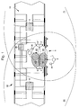
- FIG. 1 One embodiment of the detection system described in this document is represented in figure 1. It is proposed to equip each delimited space, indicated by the reference numeral 10, (for example defined by compartment 32 of a train of metro, railway wagon, bus, etc.) of low emission means frequency 4, 4 *, 5, 5 * placed at input 6 (in this case at each input). These transmission means are arranged to transmit, during the passage of an individual (indicated by the numerical reference 8) or of an object through entry 6, low frequency electromagnetic signals carrying data to one unit portable electronics (indicated by the reference numeral 36) which is equipped individual 8 or object.
- the reference numeral 10 for example defined by compartment 32 of a train of metro, railway wagon, bus, etc.
- These transmission means are arranged to transmit, during the passage of an individual (indicated by the numerical reference 8) or of an object through entry 6, low frequency electromagnetic signals carrying data to one unit portable electronics (indicated by the reference numeral 36) which is equipped individual 8 or object.
- the low-frequency transmission means 4, 4 *, 5, 5 * are arranged for transmit at relatively low frequency (of the order of a hundred kHz) at least a first low frequency electromagnetic signal in a region of communication (formed of communication regions 60, 61, 62 and 63 in the illustration in FIG. 1) essentially covering the entrance 6 to the delimited space 10.
- the detection system further comprises transmission-reception means high frequency 12, 13 associated with the delimited space 10 and making it possible to establish a relatively high frequency two-way communication (on the order of hundred MHz or more) with portable electronic units 36.
- these high frequency transmission-reception means 12, 13 comprise one or more high frequency receivers, here two in number, and one or more high frequency transmitters, also two in this example, placed in the delimited space 10 so that the communication regions, indicated by the numerical references 70 and 71, defined by these transceivers 12, 13 cover essentially the entire surface of the delimited space 10 y including entrance 6.
- These communication regions 70, 71 are in particular arranged to encompass the communication regions 61, 62, 63, 64 of the low transmitters frequency 4, 4 *, 5, 5 * placed at the inputs.
- FIG. 2 schematically shows the structure of a portable unit 36 of the Figure 1 detection system.
- This portable electronic unit includes a low frequency reception unit 46 and an antenna 28 for receiving data transmitted by means of the low frequency electromagnetic signal (s) emitted by the transmission means 4, 4 *, 5, 5 *, as well as a high transceiver block frequency 48 and an antenna 30 for exchanging data with the means high frequency transceiver 12, 13 associated with the demarcated space 10 at by means of a high frequency electromagnetic signal.
- a high frequency electromagnetic signal (designated by the reference C in the following description) is transmitted by the transceiver block 48, and a receipt receipt (designated by the reference ACK in the continuation of the description) is transmitted by the transmission-reception means 12,13 associated with the demarcated space 10.
- An electronic data processing unit 44 associated with a memory 45 is connected to the low frequency reception 46 and transceiver blocks high frequency 48.
- the electronic unit 36 is powered by a source electric power supply 24 such as a cell or other battery.
- the data processing unit 44 can be put into standby mode in order to save energy.
- the high transceiver block frequency 48 may be deactivated or put on standby by the processing unit 44 as shown schematically by the interrupt means 50.
- the electronic units 36 are normally in Eve.
- the data processing unit 44 as well as the block high frequency transmission-reception 48 are thus deactivated.
- this electronic unit 36 is activated by electromagnetic fields low frequency transmitted by the transmission means 4, 4 *, 5, 5 * and receives, via the low frequency electromagnetic signals transmitted, data relating to the space delimited in question (for example an identification of the vehicle or of the place where penetrates the individual or object, the date and time, and, if necessary, other parameters relating to the demarcated space 10).
- data relating to the space delimited in question for example an identification of the vehicle or of the place where penetrates the individual or object, the date and time, and, if necessary, other parameters relating to the demarcated space 10.
- the electronic unit 36 undertakes to communicate at high frequency by means of its transceiver block high frequency 48 with associated transmission / reception means 12, 13 to the delimited space.
- an identification of the portable electronic unit 36 is in particular transmitted to the transmission-reception means 12, 13 of the demarcated space 10 to be recorded by a computer edge 20 associated with this delimited space 10 and connected to the low emission means frequency 4, 4 *, 5, 5 * as well as the high frequency transmission-reception means 12, 13.
- the transmission-reception means 12, 13 transmit a receipt reception to the portable electronic unit 36.
- each portable electronic unit 36 can keep a register of the latest entries and exits in defined spaces, including time, date and a identification of each delimited space considered.
- each portable electronic unit once activated by low frequency electromagnetic fields, proceeds to the emission, at least once, of a high frequency electromagnetic signal at destination of high frequency transceivers 12, 13 awaiting a receipt receipt from these transceivers 12, 13.
- this high frequency electromagnetic signal, or presence interrogation signal is transmitted periodically, and as soon as the high frequency signal emitted by a portable electronic unit is no longer received by the transmission-reception means high frequency during a determined period of time, it is assumed that this unit portable electronics are no longer inside delimited space 10 and the unit portable electronics 36 is then switched to standby mode.
- this first operating mode will be designated in the following description by the acronym "BIBO” ( B e In B e O ut) meaning that the presence or absence of an electronic unit 36 in the the delimited space is determined on the basis of a reception, by the high-frequency transmission-reception means 12, 13 associated with the space 10, of a high-frequency electromagnetic signal coming from the portable electronic unit.
- BIBO B e In B e O ut
- the means of transmission include first and second low frequency transmitters, designated respectively by the reference numbers 4, 4 * and 5, 5 *, as specifically illustrated in Figure 1.
- These first and second transmitters are arranged to respectively transmit first and second low frequency electromagnetic signals (designated respectively by the references A and B in the following description) in first 60, 61 and second 62, 63 communication regions respectively spatially separated from each other and partially overlapping.
- These first 60, 61 and second 62, 63 communication regions essentially cover entry 6 in the delimited space and are respectively located towards the outside and inside of delimited space 10, so that when an individual or object enters the delimited space 10, this first meets the first A, then the second signal low frequency electromagnetic B.
- the first and second transmitters include each a pair of 4 and 4 * transmitters, respectively 5 and 5 *, placed on either side of entry 6. It will nevertheless be understood that these first and second transmitters may each include only one transmitter or possibly more than two, the main thing being that the communication regions defined by these transmitters low frequency cover the passage area of individuals or objects through entrance 6 and allow to define a succession of spatially separated regions in which are issued separate signals.
- This arrangement of the first and second low frequency transmitters 4, 4 * and 5, 5 * and their emission field aims to allow, in addition to an awakening of the units portable electronics 36, detecting the direction of passage of individuals or objects through entry 6.
- This direction of passage detection is carried out in determining the order of reception of the first and second electromagnetic signals low frequency A, B emitted respectively by transmitters 4, 4 * in the regions of communication 60, 61 and by transmitters 5, 5 * in the communication regions 62, 63.
- the detection of the direction of passage through entry 6 is carried out in particular by the electronic unit 36 based on the order of reception of the first and second low frequency electromagnetic signals A, B issued at the entrance.
- the information concerning the direction of passage is for example determined by detecting at least which of the first and second signals low frequency electromagnetic A, B was received first and last during the passage of the individual or object through entry 6.
- This meaningful information of passage namely information of entry, exit or information according to which the electronic unit 36 has remained inside or outside the space delimited is transmitted by the electronic unit 36 in the form of a signal high frequency electromagnetic to high frequency transceivers 12, 13.
- the portable electronic unit 36 is then put on standby.
- the receipt of ACK reception transmitted by transceivers 12, 13 may or may not be considered by the electronic unit 36.
- this receipt receipt ACK is considered by the electronic unit to confirm reception of the signal high frequency C.
- WIWO W alk I n W alk O ut
- WIWO the second mode of operation mentioned above
- the system detection based on the first mode of operation mentioned above, said BIBO is then preferably adopted.
- the second WIWO operating mode mentioned above is generally preferred and adopted wherever possible since it does not require the purpose of establishing the presence or absence of a portable electronic unit in the delimited space, that a short-term communication between these units electronics and the transceivers associated with the demarcated space.
- the first BIBO operating mode mentioned above typically requires exchanges between the electronic units and the transceivers associated with the space delimited in order to establish the presence or absence of an electronic unit in this space, and is therefore, compared to the second mode of operation WIWO, slightly less optimal from a consumption point of view.
- the BIBO operating mode or the WIWO operating mode is adopted by default for all delimited spaces considered. A compromise, by definition not optimal, is thus realized.
- a general aim of the present invention is therefore to propose a solution allowing to adopt one or other of the above-mentioned operating modes, or even others, depending on the type or characteristics of each delimited space considered, and in particular to adopt the operating mode best suited to the delimited space considered, this in order to increase the reliability of the detection of individuals or objects in these spaces and also optimize consumption in wherever possible.
- a particular object of the present invention is further to provide a solution with great flexibility of use allowing, if necessary, the application of several distinct operating modes for a defined space considered, this in particular in order to compensate for potential deficiencies of one or the other of the operating modes used.
- the present invention thus relates to a system for detecting individuals or objects in a plurality of delimited spaces each having at least one entry whose characteristics are set out in independent claim 1.
- the present invention also relates to detection methods including the features are set out in claims 8 to 10.
- the detection system is thus configured to operate in at least two distinct operating modes, such as the WIWO and BIBO operation mentioned above (or even others), and the signal (s) low frequency transmitted by the low frequency transmission means placed in entry have for this purpose selection information indicating which of the modes of operation must be used by portable electronic units when they are passage through the entrance.
- the system is furthermore configured to switch, at least temporarily, from an operating mode to a other for the same delimited space considered, for example switching from the second mode WIWO operating mode to the first BIBO operating mode and vice versa. It is thus possible to overcome certain problems which could potentially intervene with one or other of the operating modes used.
- a drawback of the WIWO operating mode based on the detection of the direction of passage lies in the fact that there is a probability, low, the portable electronic unit cannot correctly detect the direction of passage through the entrance. Indeed, given the physical characteristics transmission and reception of electromagnetic signals in the environment, it The sequence of signals received by the portable electronic unit may not be not coherent or sufficiently decisive and does not lead to a sure conclusion as to the direction of passage of this electronic unit through (or in the vicinity) of the entrance.
- a disadvantage of the BIBO operating mode based on the reception of the high frequency electromagnetic signal lies in the fact that there a low probability that the electromagnetic presence interrogation signal will not is not correctly received by the high frequency transmission-reception means associated with the delimited space or that the receipt of reception transmitted by the high frequency transmission-reception means associated with the demarcated space is not correctly received by the electronic unit, this could result in the unexpected standby of the portable electronic unit while it is in reality still inside the demarcated space.
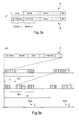
- Figure 3a shows the shape and content of the electromagnetic signals low frequency A, B transmitted to a portable electronic unit in the frame specific of an application to means of public transport. We will insist on again on the fact that the invention is in no way limited to this single application.
- the first and second low frequency electromagnetic signals A, B each include data relating to the delimited space with which the low frequency transmitters are associated placed as a starter.
- the first electromagnetic signal A can thus comprise, as illustrated, first and second words respectively indicating the date and time of passage by entering the demarcated space where this signal is issued.
- this first electromagnetic signal A may include other words, where appropriate defining various parameters for transmitting and / or receiving signals high frequency electromagnetic signals to be transmitted and / or received by the unit electronic as will emerge from the discussion of Figure 3b.
- the second signal low frequency electromagnetic B has one or more words indicating the identity of the delimited space considered (for example an identification of the vehicle, railway wagon or metro train, etc.), as well as, in the context of the application considered here, one or more words indicating the identity from the station or stop where the public transport vehicle is parked in question.
- At least one of the first and second signals low frequency electromagnetic A, B (preferably both) have a selection information, designated SELECT, which may include one or more bits information, indicating which of the operating modes should be used by the electronic units when passing through the entrance to the defined space considered.
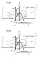
- FIG. 5a illustrates a first advantageous variant of the system according to the present invention according to which the first and second signals low frequency electromagnetic A, B both contain information of determined selection, designated SELECT_WIWO, so that the presence or the absence of an electronic unit 36 in the delimited space 10 is detected according to the WIWO operating mode.
- SELECT_WIWO information of determined selection
- the portable electronic unit 36 receives information from single selection SELECT_WIWO according to which it must operate according to the second WIWO operating mode and thus issue, after passing through input 6, a high frequency electromagnetic signal C including direction information passage detected by the electronic unit 36. Following this transmission, the unit portable electronics is preferably put on standby as already mentioned.
- FIG. 5b illustrates a second variant advantageous of the system according to the present invention according to which the first signal low frequency electromagnetic A, emitted outside the defined space 10, contains specific selection information, designated SELECT_BIBO, so that the presence or absence of an electronic unit 36 in the delimited space 10 either determined according to the first BIBO operating mode following an entry in the demarcated space.
- the second electromagnetic signal B emitted inside of the delimited space 10 comprises a specific selection information, designated SELECT_WIWO, so that the portable electronic unit 36 operates, if it is in standby mode, according to the second WIWO operating mode.
- a portable electronic unit 36 operates normally according to the first BIBO operating mode, i.e. proceeds to the emission of the high frequency electromagnetic signal C awaiting a receipt ACK reception from the high frequency transmission-reception means (12, 13 in Figure 1) associated with the delimited space 10.
- the unit portable electronics 36 operates according to the second WIWO operating mode only if it has entered standby mode when it is actually still at inside the demarcated space 10 and subsequently crosses the fields of the transmitters low frequency placed at the input 6.
- a unit portable electronics is normally only put on standby if it is actually outside the scope of sending and receiving means high frequency transmission-reception associated with the defined space and does not receive consequence no more ACK receipt receipt.
- the selection information transmitted by the second signal electromagnetic B is thus not considered.
- Figure 3b shows the shape and content of the high electromagnetic signal frequency C transmitted by a portable electronic unit as well as the receipt of ACK reception transmitted by high frequency transmission-reception means associated with the demarcated space.
- the high frequency electromagnetic signal C transmitted by the portable electronic unit 36 includes in particular an identification number ID of the electronic unit, information concerning the date and time of passage by the entry and, if applicable, the direction of passage detection information, designated DIRECTION, if the system operates according to the WIWO operating mode.
- a sequence formed by N repetitions of the above-mentioned data is preferably transmitted several times (by example with a maximum M of repetitions) with a repetition period T1.
- the transmission of the high frequency signal C is preferably carried out in this way to provide some redundancy.
- the emission of the above-mentioned sequences is also repeated periodically with a T2 repeat period.
- the aforementioned T1 and T2 repeat periods as well as, where applicable, the repetition parameters N and M are preferably transmitted by means of the low frequency electromagnetic signals A and / or B. Note that these parameters are adapted according to the characteristics of the delimited space considered and can, if necessary, be adapted over time, for example depending on the time between two successive stops of the transport vehicle.
- the high transmission-reception means frequency associated with the demarcated space issue a receipt of ACK reception (both in the first and second BIBO operating modes and WIWO) as soon as the high frequency electromagnetic signal C has been received correctly.
- Figure 4 shows a flowchart illustrating the flow of the detection of the presence or absence of an electronic unit according to this invention.
- the detection process begins at step S100 with an electronic unit in standby mode. As soon as the portable electronic unit picks up one of the two low frequency electromagnetic signals A, B (step S102), the means for data processing 44 of the electronic unit is activated (step S104) and these read and identify the selection information SELECT contained in the first electromagnetic signal received (step S106), namely the first A or second low frequency electromagnetic signal B.
- this SELECT selection information matches the information in determined selection SELECT_WIWO indicating that the electronic unit must operate depending on the WIWO operating mode, the electronic unit first of all detecting the direction of passage DIRECTION (step S108), then activating the block high frequency reception 30, 48 (step S112) and finally to signal transmission high frequency electromagnetic C containing the direction of passage information DIRECTION (step S114).
- the electronic unit If the SELECT selection information matches the selection information determined SELECT_BIBO indicating that the electronic unit must operate according to the BIBO operating mode, the electronic unit first activates of the high frequency reception block 30, 48 (step S109), then the transmission of the high frequency electromagnetic signal C (step S111), and checking the receipt of ACK receipt receipt (step S113), the latter step being repeated as long as this ACK receipt receipt is received.
- step S114 the means for data processing 44 as well as the high frequency transceiver block 30, 48 of the electronic unit are deactivated (step S116) and the latter then goes to again in standby mode and the detection process can start again in step S100.
- the detection of the direction of passage is for example carried out by the portable electronic unit based on the order of reception of the first and second low frequency electromagnetic signals A, B emitted at the input, by example by detecting at least which of the first and second low frequency electromagnetic signals A, B was received first and last during the passage of the individual or the object by entry 6.
- a truth table comprising at least the identifications of the first and last low frequency signals received.
- the table below shows by way of example a truth table formed of the identifications of the first, penultimate and last low frequency signals received as well as the resulting interpretation of the direction of passage.
- First signal received Penultimate signal received Last signal received Conclusion 1 AT AT AT AT stayed outside 2 AT AT B Entrance 3 AT B AT undefined state 4 AT B B Entrance 5 B AT AT exit 6 B AT B undefined state 7 B B AT exit 8 B B B stay indoors
- states 3 and 6 do not allow conclude to an entry, an exit, or to the fact that the portable electronic unit is stayed inside or outside the defined space.
- states 2 and 7 correspond respectively to an input and an output of a unit electronic. It will of course be understood that these states could also be considered as undefined states.
- step S110 where, if such ambiguity in the direction of passage is detected, the process continues with step S109 of activation of the transmit-receive block 30, 48 followed by steps S111 and S113.
- the portable electronic unit In either of the above cases where the portable electronic unit is switched from one operating mode to another, it should be included in the high frequency electromagnetic signal C transmitted by the electronic unit, a information indicating that the latter has carried out this switching, i.e. a information analogous to the SELECT selection information transmitted by the low frequency electromagnetic input signals.
- the low frequency transmission means 4, 4 *, 5, 5 * are illustrated as being arranged in compartment 32 of the vehicle.
- these low frequency transmission means are associated with the delimited space considered, that is to say that they transmit in particular information relating to this delimited space.
- the transmitters of the first low frequency electromagnetic signal A which are located towards the outside of the delimited space are not arranged inside the vehicle compartment but are fixedly arranged on the platform or stop where passengers get on and off.
- the transmission-reception means high frequency can also be arranged outside the compartment vehicle, for example in platform access corridors or directly on these docks.
Abstract
Description
L'invention concerne la détection d'individus ou d'objets dans des espaces délimités présentant chacun au moins une entrée. Par entrée, il faut comprendre de manière large toute porte ou chemin de passage donnant accès à l'espace délimité en question. A titre d'exemple, il est prévu de détecter la présence d'individus lors d'un trajet dans un transport public ou lors d'un événement sportif ou culturel ayant lieu dans un endroit délimité.The invention relates to the detection of individuals or objects in spaces delimited each with at least one entry. By entry, we must understand wide any door or passage way giving access to the space delimited by question. For example, it is planned to detect the presence of individuals during a journey in public transport or during a sporting or cultural event taking place in a demarcated place.
Dans le cadre de la présente invention, il est prévu de détecter la présence d'individus ou d'objets au moyen de cartes ou d'unités électroniques portables ayant des moyens pour recevoir et émettre des données sous la forme de signaux électromagnétiques. Il est prévu de munir les individus ou objets de telles unités électroniques portables.In the context of the present invention, it is intended to detect the presence individuals or objects by means of portable electronic cards or units having means for receiving and transmitting data in the form of signals electromagnetic. It is planned to equip individuals or objects with such units portable electronics.
La demande internationale WO 01/03057, incorporée ici par référence, également au nom du présent Déposant, décrit un tel procédé de détection ainsi qu'un système de détection d'individus ou d'objets dans un espace délimité présentant une entrée.International application WO 01/03057, incorporated here by reference, also in the name of the present Applicant, describes such a detection method as well than a system for detecting individuals or objects in a defined space presenting an entry.
Un mode de réalisation du système de détection décrit dans ce document est
représenté à la figure 1. Il est proposé de munir chaque espace délimité, indiqué par
la référence numérique 10, (par exemple défini par le compartiment 32 d'une rame de
métro, d'un wagon de chemin de fer, d'un autobus, etc.) de moyens d'émission basse
fréquence 4, 4*, 5, 5* placés à l'entrée 6 (en l'occurrence à chaque entrée). Ces
moyens d'émission sont agencés pour transmettre, lors du passage d'un individu
(indiqué par la référence numérique 8) ou d'un objet au travers de l'entrée 6, des
signaux électromagnétiques basse fréquence portant des données à une unité
électronique portable (indiquée par la référence numérique 36) dont est équipé
l'individu 8 ou l'objet.One embodiment of the detection system described in this document is
represented in figure 1. It is proposed to equip each delimited space, indicated by
the
Les moyens d'émission basse fréquence 4, 4*, 5, 5* sont agencés pour
émettre à relativement basse fréquence (de l'ordre d'une centaine de kHz) au moins
un premier signal électromagnétique basse fréquence dans une région de
communication (formée des régions de communication 60, 61, 62 et 63 dans
l'illustration de la figure 1) couvrant essentiellement l'entrée 6 à l'espace délimité 10.The low-frequency transmission means 4, 4 *, 5, 5 * are arranged for
transmit at relatively low frequency (of the order of a hundred kHz) at least
a first low frequency electromagnetic signal in a region of
communication (formed of
Le système de détection comporte en outre des moyens d'émission-réception
haute fréquence 12, 13 associés à l'espace délimité 10 et permettant d'établir une
communication bidirectionnelle à relativement haute fréquence (de l'ordre d'une
centaine de MHz ou plus) avec les unités électroniques portables 36. Plus
exactement, ces moyens d'émission-réception haute fréquence 12, 13 comprennent
un ou plusieurs récepteurs haute fréquence, ici au nombre de deux, et un ou plusieurs
émetteurs haute fréquence, également au nombre de deux dans cet exemple, placés
dans l'espace délimité 10 de manière à ce que les régions de communication,
indiquées par les références numériques 70 et 71, définies par ces émetteurs-récepteurs
12, 13 couvrent essentiellement toute la surface de l'espace délimité 10 y
compris l'entrée 6. Ces régions de communication 70, 71 sont en particulier agencées
pour englober les régions de communication 61, 62, 63, 64 des émetteurs basse
fréquence 4, 4*, 5, 5* placés aux entrées.The detection system further comprises transmission-reception means
Dans la figure 1, seul un espace délimité est illustré. On comprendra néanmoins que tous les espaces délimités, définis par exemple par l'ensemble des rames d'un métro ou des compartiments du moyen de transport considéré, sont équipés chacun de moyens d'émission et de réception analogues.In Figure 1, only a delimited space is illustrated. We will understand nevertheless that all the delimited spaces, defined for example by the set of subway trains or compartments of the means of transport considered, are each equipped with similar transmitting and receiving means.
La figure 2 montre schématiquement la structure d'une unité portable 36 du
système de détection de la figure 1. Cette unité électronique portable comporte un
bloc de réception basse fréquence 46 et une antenne 28 pour recevoir les données
transmises au moyen du ou des signaux électromagnétiques basse fréquence émis
par les moyens d'émission 4, 4*, 5, 5*, ainsi qu'un bloc d'émission-réception haute
fréquence 48 et une antenne 30 pour échanger des données avec les moyens
d'émission-réception haute fréquence 12, 13 associés à l'espace délimité 10 au
moyen d'un signal électromagnétique haute fréquence. En l'occurrence, comme on le
verra en détail ci-après, un signal électromagnétique haute fréquence (désigné par la
référence C dans la suite de la description) est transmis par le bloc d'émission-réception
48, et une quittance de réception (désigné par la référence ACK dans la
suite de la description) est transmise par les moyens d'émission-réception 12,13
associés à l'espace délimité 10.FIG. 2 schematically shows the structure of a
Une unité électronique de traitement de données 44 associée à une mémoire
45 est connectée aux blocs de réception basse fréquence 46 et d'émission-réception
haute fréquence 48. L'unité électronique 36 est alimentée par une source
d'alimentation en énergie électrique 24 telle une pile ou autre batterie.
Préférablement, l'unité de traitement de données 44 peut être mise en mode de veille
afin d'économiser de l'énergie. De même, le bloc d'émission-réception haute
fréquence 48 est susceptible d'être désactivé ou mis en veille par l'unité de traitement
de données 44 comme schématisé par le moyen d'interruption 50. Ainsi, seul le bloc
de réception basse fréquence 46 est alimenté en permanence ou quasi permanence,
celui-ci activant l'unité de traitement de données 44 dès lors qu'un signal
électromagnétique basse fréquence émis par les moyens d'émission basse fréquence
est reçu par ce bloc de réception 46.An electronic
Selon un mode de fonctionnement général décrit dans la demande
internationale susmentionnée, les unités électroniques 36 sont normalement en mode
de veille. En mode de veille, l'unité de traitement de données 44 ainsi que le bloc
d'émission-réception haute fréquence 48 sont ainsi désactivés. Dès lors qu'une unité
électronique 36 en mode de veille traverse une entrée du système, telle l'entrée 6 de
la figure 1, cette unité électronique 36 est activée par les champs électromagnétiques
basse fréquence émis par les moyens d'émission 4, 4*, 5, 5* et reçoit, via le ou les
signaux électromagnétiques basse fréquence transmis, des données relatives à
l'espace délimité en question (par exemple une identification du véhicule ou du lieu où
pénètre l'individu ou l'objet, la date et l'heure, et, le cas échéant, d'autres paramètres
relatifs à l'espace délimité 10). Ces données sont mémorisées dans la mémoire 45 de
l'unité électronique portable 36.According to a general operating mode described in the request
mentioned above, the
Dès lors que l'unité électronique 36 a été activée et a traversé l'entrée 6, celle-ci
entreprend de communiquer à haute fréquence au moyen de son bloc d'émission-réception
haute fréquence 48 avec les moyens d'émission-réception 12, 13 associés
à l'espace délimité. Durant cette communication haute fréquence, une identification de
l'unité électronique portable 36 est notamment transmise aux moyens d'émission-réception
12, 13 de l'espace délimité 10 pour être enregistrée par un ordinateur de
bord 20 associé à cet espace délimité 10 et relié aux moyens d'émission basse
fréquence 4, 4*, 5, 5* ainsi qu'aux moyens d'émission-réception haute fréquence 12,
13. En réponse, les moyens d'émission-réception 12, 13 transmettent une quittance
de réception à destination de l'unité électronique portable 36.As soon as the
L'ordinateur de bord 20, ou plus généralement l'unité centrale de traitement,
tient ainsi à jour un registre contenant les informations d'entrée et de sortie de chaque
unité électronique ayant pénétré dans l'espace délimité 10. De manière similaire,
chaque unité électronique portable 36 peut tenir à jour un registre des dernières
entrées et sorties dans des espaces délimités, notamment l'heure, la date et une
identification de chaque espace délimité considéré.The on-
Selon un mode de fonctionnement particulier du système de détection décrit
dans la demande internationale susmentionnée, chaque unité électronique portable,
une fois activée par les champs électromagnétiques basse fréquence, procède à
l'émission, au moins une fois, d'un signal électromagnétique haute fréquence à
destination des émetteurs-récepteurs haute fréquence 12, 13 en attente d'une
quittance de réception provenant de ces émetteurs-récepteurs 12, 13. Typiquement,
ce signal électromagnétique haute fréquence, ou signal d'interrogation de présence,
est émis de manière périodique, et, dès lors que le signal haute fréquence émis par
une unité électronique portable n'est plus reçu par les moyens d'émission-réception
haute fréquence durant une période de temps déterminée, on admet que cette unité
électronique portable ne se trouve plus à l'intérieur de l'espace délimité 10 et l'unité
électronique portable 36 est alors commutée en mode de veille.According to a particular operating mode of the detection system described
in the above-mentioned international application, each portable electronic unit,
once activated by low frequency electromagnetic fields, proceeds to
the emission, at least once, of a high frequency electromagnetic signal at
destination of
Par souci de simplification, ce premier mode de fonctionnement sera désigné
dans la suite de la description par l'acronyme « BIBO » (Be In Be Out) signifiant que
la présence ou l'absence d'une unité électronique 36 dans l'espace délimité est
déterminée sur la base d'une réception, par les moyens d'émission-réception haute
fréquence 12, 13 associés à l'espace 10, d'un signal électromagnétique haute
fréquence provenant de l'unité électronique portable.For the sake of simplification, this first operating mode will be designated in the following description by the acronym "BIBO" ( B e In B e O ut) meaning that the presence or absence of an
Selon une variante particulière du système de détection décrit dans la
demande internationale susmentionnée, les moyens d'émission comportent des
premier et second émetteurs basse fréquence, désignés respectivement par les
références numériques 4, 4* et 5, 5*, comme illustré spécifiquement dans la figure 1.
Ces premier et second émetteurs sont agencés pour émettre respectivement des
premier et second signaux électromagnétiques basse fréquence (désignés
respectivement par les références A et B dans la suite de la description) dans
respectivement des première 60, 61 et seconde 62, 63 régions de communication
séparées spatialement l'une de l'autre et se recouvrant partiellement. Ces première
60, 61 et seconde 62, 63 régions de communication couvrent essentiellement l'entrée
6 à l'espace délimité et sont respectivement situées vers l'extérieur et vers l'intérieur
de l'espace délimité 10, de sorte que, lorsqu'un individu ou objet pénètre dans
l'espace délimité 10, celui-ci rencontre tout d'abord le premier A, puis le second signal
électromagnétique basse fréquence B.According to a particular variant of the detection system described in the
above-mentioned international application, the means of transmission include
first and second low frequency transmitters, designated respectively by the
Dans l'illustration de la figure 1, les premier et second émetteurs comprennent
chacun une paire d'émetteurs 4 et 4*, respectivement 5 et 5*, placés de part et d'autre
de l'entrée 6. On comprendra néanmoins que ces premier et second émetteurs
peuvent ne comprendre, chacun, qu'un seul émetteur ou éventuellement plus de
deux, l'essentiel étant que les régions de communication définies par ces émetteurs
basse fréquence couvrent la zone de passage des individus ou objets par l'entrée 6 et
permettent de définir une succession de régions spatialement séparées dans
lesquelles sont émis des signaux distincts.In the illustration of Figure 1, the first and second transmitters include
each a pair of 4 and 4 * transmitters, respectively 5 and 5 *, placed on either side
of
Cette disposition des premier et second émetteurs basse fréquence 4, 4* et 5,
5* et de leur champ d'émission a pour but de permettre, outre un éveil des unités
électroniques portables 36, la détection du sens de passage des individus ou objets
au travers de l'entrée 6. Cette détection de sens de passage est effectuée en
déterminant l'ordre de réception des premier et second signaux électromagnétiques
basse fréquence A, B émis respectivement par les émetteur 4, 4* dans les régions de
communication 60, 61 et par les émetteurs 5, 5* dans les régions de communication
62, 63.This arrangement of the first and second
Une réalisation d'un système de détection de passage est plus particulièrement décrite dans la demande de brevet européen No. 00204758.8 du 29.12.2000 intitulée « Système de détection du passage d'un individu ou objet par une entrée-sortie à un espace délimité » également au nom du présent Déposant.A realization of a passage detection system is more particularly described in European patent application No. 00204758.8 of 12.29.2000 entitled "System for detecting the passage of an individual or object through a entry-exit to a delimited space ”also in the name of this Applicant.
Selon cette demande, la détection du sens de passage au travers de l'entrée 6
est notamment effectuée par l'unité électronique 36 en se basant sur l'ordre de
réception des premier et second signaux électromagnétiques basse fréquence A, B
émis à l'entrée. L'information concernant le sens de passage est par exemple
déterminée en détectant au moins lequel des premier et second signaux
électromagnétiques basse fréquence A, B a été reçu en premier et en dernier lieu
durant le passage de l'individu ou de l'objet par l'entrée 6. Cette information de sens
de passage, à savoir une information d'entrée, de sortie ou une information selon
laquelle l'unité électronique 36 est restée à l'intérieur ou à l'extérieure de l'espace
délimité est transmise par l'unité électronique 36 sous la forme d'un signal
électromagnétique haute fréquence aux émetteurs-récepteurs haute fréquence 12,
13. Une fois l'information de sens de passage transmise, l'unité électronique portable
36 est alors mise en veille. Dans ce mode de fonctionnement, la quittance de
réception ACK transmise par les émetteurs-récepteurs 12, 13 peut ou non être
considérée par l'unité électronique 36. Préférablement, cette quittance de réception
ACK est considérée par l'unité électronique afin de confirmer la réception du signal
haute fréquence C.According to this request, the detection of the direction of passage through
Par souci de simplification, ce second mode de fonctionnement sera désigné
dans la suite de la description par l'acronyme « WIWO » (Walk In Walk Out) signifiant
que la présence ou l'absence d'une unité électronique 36 dans l'espace délimité est
déterminée sur la base de l'information de sens de passage au travers l'entrée 6.For simplicity, this second mode of operation will be designated in the following description by the acronym "WIWO" ( W alk I n W alk O ut) meaning that the presence or absence of an
Dans une application typique du système de détection susmentionné, telle que la facturation automatique de trajets effectués par des utilisateurs au moyen de transports publics, on désirera équiper les divers véhicules du réseau de transport public d'un système de détection fonctionnant de manière aussi optimale que possible afin de détecter avec une grande fiabilité la présence ou l'absence des individus dans ces divers véhicules.In a typical application of the above-mentioned detection system, such as automatic billing of journeys made by users using public transport, we will want to equip the various vehicles of the transport network detection system working as optimally as possible in order to reliably detect the presence or absence of individuals in these various vehicles.
En raison de considérations pratiques notamment liées aux possibilités de montage des émetteurs basse fréquence placés aux entrées aux espaces délimités définis par les compartiments des véhicules, il est plus ou moins aisé de mettre en oeuvre le second mode de fonctionnement susmentionné dit WIWO, c'est-à-dire le mode de fonctionnement basé sur la détection du sens de passage des unités électroniques portables au travers des entrées. Toutefois, si les possibilités de montage des émetteurs basse fréquence aux entrées sont limitées ou peu adéquates pour permettre une détection fiable du sens de passage par ces entrées, le système de détection basé sur le premier mode de fonctionnement susmentionné dit BIBO est alors préférablement adopté.Due to practical considerations, notably related to the possibilities of mounting of low frequency transmitters placed at the entrances to the demarcated spaces defined by vehicle compartments, it is more or less easy to set up works the second mode of operation mentioned above called WIWO, that is to say the operating mode based on the detection of the direction of passage of the units portable electronics through inputs. However, if the possibilities of installation of low frequency transmitters at the inputs is limited or not adequate to allow reliable detection of the direction of passage through these inputs, the system detection based on the first mode of operation mentioned above, said BIBO is then preferably adopted.
On notera que le second mode de fonctionnement WIWO susmentionné est généralement préféré et adopté dans la mesure du possible puisqu'il ne requiert, dans le but d'établir la présence ou l'absence d'une unité électronique portable dans l'espace délimité, qu'une communication de courte durée entre ces unités électroniques et les émetteurs-récepteurs associés à l'espace délimité. Le premier mode de fonctionnement BIBO susmentionné nécessite typiquement des échanges périodiques entre les unités électroniques et les émetteurs-récepteurs associés à l'espace délimité afin d'établir la présence ou l'absence d'une unité électronique dans cet espace, et est donc, comparativement au second mode de fonctionnement WIWO, légèrement moins optimal du point de vue de la consommation.Note that the second WIWO operating mode mentioned above is generally preferred and adopted wherever possible since it does not require the purpose of establishing the presence or absence of a portable electronic unit in the delimited space, that a short-term communication between these units electronics and the transceivers associated with the demarcated space. The first BIBO operating mode mentioned above typically requires exchanges between the electronic units and the transceivers associated with the space delimited in order to establish the presence or absence of an electronic unit in this space, and is therefore, compared to the second mode of operation WIWO, slightly less optimal from a consumption point of view.
Jusqu'à maintenant, étant donné que les unités électroniques portables ne sont pas à même de déterminer a priori si le système opère sur la base du premier ou du second mode de fonctionnement susmentionné, le mode de fonctionnement BIBO ou le mode de fonctionnement WIWO est adopté par défaut pour l'ensemble des espaces délimités considérés. Un compromis, par définition non optimal, est ainsi réalisé.Until now, since portable electronic units do not are not able to determine a priori whether the system operates on the basis of the first or of the aforementioned second operating mode, the BIBO operating mode or the WIWO operating mode is adopted by default for all delimited spaces considered. A compromise, by definition not optimal, is thus realized.
Un but général de la présente invention est donc de proposer une solution permettant d'adopter l'un ou l'autre des modes de fonctionnement susmentionnés, voire d'autres, selon le type ou les caractéristiques de chaque espace délimité considéré, et en particulier d'adopter le mode de fonctionnement le mieux adapté à l'espace délimité considéré, ceci afin d'accroítre la fiabilité de la détection des individus ou objets dans ces espaces et également optimiser la consommation dans la mesure du possible.A general aim of the present invention is therefore to propose a solution allowing to adopt one or other of the above-mentioned operating modes, or even others, depending on the type or characteristics of each delimited space considered, and in particular to adopt the operating mode best suited to the delimited space considered, this in order to increase the reliability of the detection of individuals or objects in these spaces and also optimize consumption in wherever possible.
Un but particulier de la présente invention est en outre de proposer une solution présentant une grande flexibilité d'utilisation permettant, le cas échéant, l'application de plusieurs modes de fonctionnement distincts pour un espace délimité considéré, ceci notamment afin de pallier à des déficiences potentielles de l'un ou l'autre des modes de fonctionnement utilisés.A particular object of the present invention is further to provide a solution with great flexibility of use allowing, if necessary, the application of several distinct operating modes for a defined space considered, this in particular in order to compensate for potential deficiencies of one or the other of the operating modes used.
La présente invention a ainsi pour objet un système de détection d'individus ou d'objets dans une pluralité d'espaces délimités présentant chacun au moins une entrée dont les caractéristiques sont énoncées dans la revendication indépendante 1.The present invention thus relates to a system for detecting individuals or objects in a plurality of delimited spaces each having at least one entry whose characteristics are set out in independent claim 1.
Des modes de réalisations avantageux de la présente invention font l'objet des revendications dépendantes.Advantageous embodiments of the present invention are the subject of dependent claims.
La présente invention a également pour objet des procédés de détection dont
les caractéristiques sont énoncées dans les revendications 8 à 10.The present invention also relates to detection methods including
the features are set out in
Selon l'invention, le système de détection est ainsi configuré pour fonctionner dans au moins deux modes de fonctionnement distincts, tels les modes de fonctionnement WIWO et BIBO susmentionnés (voire d'autres), et le ou les signaux basse fréquence transmis par les moyens d'émission basse fréquence placés en entrée comportent à cet effet une information de sélection indiquant lequel des modes de fonctionnement doit être utilisé par les unités électroniques portables lors de leur passage par l'entrée.According to the invention, the detection system is thus configured to operate in at least two distinct operating modes, such as the WIWO and BIBO operation mentioned above (or even others), and the signal (s) low frequency transmitted by the low frequency transmission means placed in entry have for this purpose selection information indicating which of the modes of operation must be used by portable electronic units when they are passage through the entrance.
De la sorte, il est possible de faire cohabiter plusieurs modes de fonctionnement distincts et ainsi adopter le mode de fonctionnement le plus adéquat et le plus optimal pour l'espace délimité considéré. La fiabilité de la détection des individus ou des objets s'en trouve ainsi améliorée.In this way, it is possible to coexist several modes of separate operations and thus adopt the most suitable operating mode and the most optimal for the delimited space considered. Reliable detection of individuals or objects are thereby improved.
Selon un mode de réalisation préféré de l'invention, le système est en outre configuré pour passer, au moins temporairement, d'un mode de fonctionnement à un autre pour le même espace délimité considéré, par exemple passer du second mode de fonctionnement WIWO au premier mode de fonctionnement BIBO et inversement. Il est de la sorte possible de pallier à certains problèmes pouvant potentiellement intervenir avec l'un ou l'autre des modes de fonctionnement utilisé.According to a preferred embodiment of the invention, the system is furthermore configured to switch, at least temporarily, from an operating mode to a other for the same delimited space considered, for example switching from the second mode WIWO operating mode to the first BIBO operating mode and vice versa. It is thus possible to overcome certain problems which could potentially intervene with one or other of the operating modes used.
Par exemple, un inconvénient du mode de fonctionnement WIWO basé sur la détection du sens de passage réside dans le fait qu'il existe une probabilité, faible, que l'unité électronique portable ne puisse pas détecter correctement le sens de passage au travers de l'entrée. En effet, compte tenu des caractéristiques physiques d'émission et de réception des signaux électromagnétiques dans l'environnement, il se peut que la séquence des signaux reçus par l'unité électronique portable ne soit pas cohérente ou suffisamment déterminante et ne permette pas d'aboutir à une conclusion sûre quant au sens de passage de cette unité électronique au travers (ou au voisinage) de l'entrée.For example, a drawback of the WIWO operating mode based on the detection of the direction of passage lies in the fact that there is a probability, low, the portable electronic unit cannot correctly detect the direction of passage through the entrance. Indeed, given the physical characteristics transmission and reception of electromagnetic signals in the environment, it The sequence of signals received by the portable electronic unit may not be not coherent or sufficiently decisive and does not lead to a sure conclusion as to the direction of passage of this electronic unit through (or in the vicinity) of the entrance.
Bien que cette probabilité d'erreur soit relativement faible, il est désirable de rendre le système aussi robuste que possible afin d'éviter au maximum ce type d'erreurs. Une commutation du second mode de fonctionnement WIWO au premier mode de fonctionnement BIBO permet de lever une telle ambiguïté.Although this probability of error is relatively low, it is desirable to make the system as robust as possible in order to avoid this type as much as possible errors. Switching from the second WIWO operating mode to the first BIBO operating mode makes it possible to remove such ambiguity.
De même, un inconvénient du mode de fonctionnement BIBO basé sur la réception du signal électromagnétique haute fréquence réside dans le fait qu'il existe une probabilité, faible, que le signal électromagnétique d'interrogation de présence ne soit pas correctement reçu par les moyens d'émission-réception haute fréquence associés à l'espace délimité ou que la quittance de réception transmise par les moyens d'émission-réception haute fréquence associés à l'espace délimité ne soit pas correctement reçue par l'unité électronique, ceci pouvant avoir pour conséquence la mise en veille inopinée de l'unité électronique portable alors que celle-ci se trouve en réalité encore à l'intérieur de l'espace délimité.Likewise, a disadvantage of the BIBO operating mode based on the reception of the high frequency electromagnetic signal lies in the fact that there a low probability that the electromagnetic presence interrogation signal will not is not correctly received by the high frequency transmission-reception means associated with the delimited space or that the receipt of reception transmitted by the high frequency transmission-reception means associated with the demarcated space is not correctly received by the electronic unit, this could result in the unexpected standby of the portable electronic unit while it is in reality still inside the demarcated space.
Une commutation du premier mode de fonctionnement BIBO au second mode de fonctionnement WIWO permet de corriger une telle erreur d'interprétation.Switching from the first BIBO operating mode to the second mode WIWO allows correcting such an interpretation error.
D'autres caractéristiques et avantages de la présente invention apparaítront plus clairement à la lecture de la description détaillée qui suit, faite en référence aux dessins annexés donnés à titre d'exemples non limitatifs et dans lesquels :
- la figure 1, déjà présentée, est une illustration schématique d'un système de détection d'individus ou d'objets;
- la figure 2, déjà présentée, montre schématiquement un mode de réalisation d'une unité électronique portable du système de la figure 1 ;
- les figure 3a et 3b illustrent l'allure, respectivement, des signaux électromagnétiques basse fréquence et haute fréquence échangés entre une unité électronique portable et les émetteurs et récepteurs associés à l'espace délimité ;
- la figure 4 est un organigramme illustrant le déroulement du processus de détection de la présence ou de l'absence d'une unité électronique selon la présente invention ; et
- les figures 5a et 5b illustrent des première et seconde variantes de réalisation avantageuses du système de détection selon la présente invention.
- Figure 1, already presented, is a schematic illustration of a system for detecting individuals or objects;
- Figure 2, already presented, schematically shows an embodiment of a portable electronic unit of the system of Figure 1;
- FIGS. 3a and 3b illustrate the shape, respectively, of the low frequency and high frequency electromagnetic signals exchanged between a portable electronic unit and the transmitters and receivers associated with the delimited space;
- Figure 4 is a flowchart illustrating the flow of the process of detecting the presence or absence of an electronic unit according to the present invention; and
- Figures 5a and 5b illustrate first and second advantageous alternative embodiments of the detection system according to the present invention.
La figure 3a montre l'allure et le contenu des signaux électromagnétiques basse fréquence A, B transmis à une unité électronique portable dans le cadre spécifique d'une application à des moyens de transports publics. On insistera à nouveau sur le fait que l'invention n'est nullement limitée à cette seule application.Figure 3a shows the shape and content of the electromagnetic signals low frequency A, B transmitted to a portable electronic unit in the frame specific of an application to means of public transport. We will insist on again on the fact that the invention is in no way limited to this single application.
A titre d'exemple purement illustratif et non limitatif, les premier et second signaux électromagnétiques basse fréquence A, B comprennent chacun des données relatives à l'espace délimité auquel sont associés les émetteurs basse fréquence placés en entrée. Ainsi, les premier et second signaux électromagnétiques A, B comprennent chacun une séquence de code décomposée, de manière non limitative, en une pluralité de mots de code WRD_i, i = 1, 2, ..., et se terminant préférablement et typiquement par un mot de vérification ou CRC comme illustré schématiquement dans la figure 3a. As a purely illustrative and nonlimiting example, the first and second low frequency electromagnetic signals A, B each include data relating to the delimited space with which the low frequency transmitters are associated placed as a starter. Thus, the first and second electromagnetic signals A, B each include a non-limiting decomposed code sequence, in a plurality of code words WRD_i, i = 1, 2, ..., and preferably ending and typically by a verification word or CRC as illustrated schematically in Figure 3a.
Le premier signal électromagnétique A peut ainsi comprendre, comme illustré, des premier et second mots indiquant respectivement la date et l'heure de passage par l'entrée à l'espace délimité où ce signal est émis. En complément, ce premier signal électromagnétique A peut comprendre, le cas échéant, d'autres mots définissant divers paramètres d'émission et/ou de réception des signaux électromagnétiques haute fréquence devant être émis et/ou reçu par l'unité électronique comme cela ressortira de la discussion de la figure 3b.The first electromagnetic signal A can thus comprise, as illustrated, first and second words respectively indicating the date and time of passage by entering the demarcated space where this signal is issued. In addition, this first electromagnetic signal A may include other words, where appropriate defining various parameters for transmitting and / or receiving signals high frequency electromagnetic signals to be transmitted and / or received by the unit electronic as will emerge from the discussion of Figure 3b.
Dans l'exemple non limitatif de la figure 3a, le second signal électromagnétique basse fréquence B comporte quant à lui un ou plusieurs mots indiquant l'identité de l'espace délimité considéré (par exemple une identification du véhicule, du wagon de chemin de fer ou encore de la rame de métro, etc.), ainsi que, dans le cadre de l'application considérée ici, un ou plusieurs mots indiquant l'identité de la station ou de l'arrêt auquel est stationné le véhicule de transport public en question.In the nonlimiting example of FIG. 3a, the second signal low frequency electromagnetic B has one or more words indicating the identity of the delimited space considered (for example an identification of the vehicle, railway wagon or metro train, etc.), as well as, in the context of the application considered here, one or more words indicating the identity from the station or stop where the public transport vehicle is parked in question.
Selon l'invention, au moins l'un des premier et second signaux électromagnétiques basse fréquence A, B (préférablement les deux) comportent une information de sélection, désignée SELECT, pouvant comprendre un ou plusieurs bits d'information, indiquant lequel des modes de fonctionnement doit être utilisé par les unités électroniques lors de leur passage par l'entrée à l'espace délimité considéré.According to the invention, at least one of the first and second signals low frequency electromagnetic A, B (preferably both) have a selection information, designated SELECT, which may include one or more bits information, indicating which of the operating modes should be used by the electronic units when passing through the entrance to the defined space considered.
A titre d'exemple, la figure 5a illustre une première variante avantageuse du
système selon la présente invention selon laquelle les premier et second signaux
électromagnétiques basse fréquence A, B comportent tous deux une information de
sélection déterminée, désignée SELECT_WIWO, de sorte que la présence ou
l'absence d'une unité électronique 36 dans l'espace délimité 10 soit détectée selon le
mode de fonctionnement WIWO.By way of example, FIG. 5a illustrates a first advantageous variant of the
system according to the present invention according to which the first and second signals
low frequency electromagnetic A, B both contain information of
determined selection, designated SELECT_WIWO, so that the presence or
the absence of an
Ainsi, selon cette variante, si l'unité électronique 36 pénètre ou sort de l'espace
délimité comme illustré schématiquement par les flèches 100 et 200, respectivement,
ou si cette unité électronique 36 pénètre dans les champs basse fréquence mais reste
à l'extérieur ou à l'intérieur de l'espace délimité 10 comme illustré respectivement par
les flèches 105 et 205, l'unité électronique portable 36 reçoit une information de
sélection unique SELECT_WIWO selon laquelle elle doit opérer selon le second
mode de fonctionnement WIWO et ainsi émettre, suite au passage par l'entrée 6, un
signal électromagnétique haute fréquence C comprenant l'information de sens de
passage détectée par l'unité électronique 36. Suite à cette transmission, l'unité
électronique portable est préférablement mise en veille comme déjà mentionné.Thus, according to this variant, if the
Encore à titre d'exemple, la figure 5b illustre une seconde variante
avantageuse du système selon la présente invention selon laquelle le premier signal
électromagnétique basse fréquence A, émis vers l'extérieur de l'espace délimité 10,
comporte une information de sélection déterminée, désignée SELECT_BIBO, de sorte
que la présence ou l'absence d'une unité électronique 36 dans l'espace délimité 10
soit déterminée selon le premier mode de fonctionnement BIBO suite à une entrée
dans l'espace délimité. Le second signal électromagnétique B émis vers l'intérieur de
l'espace délimité 10 comporte quant à lui une information de sélection déterminée,
désignée SELECT_WIWO, de sorte que l'unité électronique portable 36 opère, si
celle-ci se trouve en mode de veille, selon le second mode de fonctionnement WIWO.Again by way of example, FIG. 5b illustrates a second variant
advantageous of the system according to the present invention according to which the first signal
low frequency electromagnetic A, emitted outside the defined
Selon cette seconde variante, une unité électronique portable 36 opère
normalement selon le premier mode de fonctionnement BIBO, c'est-à-dire procède à
l'émission du signal électromagnétique haute fréquence C en attente d'une quittance
de réception ACK de la part des moyens d'émission-réception haute fréquence (12,
13 dans la figure 1) associés à l'espace délimité 10. Selon cette variante, l'unité
électronique portable 36 n'opère selon le second mode de fonctionnement WIWO que
si celle-ci est entrée en mode de veille alors qu'elle se trouve en réalité encore à
l'intérieur de l'espace délimité 10 et traverse ultérieurement les champs des émetteurs
basse fréquence placés à l'entrée 6.According to this second variant, a portable
On rappellera que, selon le mode de fonctionnement BIBO, une unité électronique portable n'est normalement mise en veille que si celle-ci se trouve effectivement en dehors du champ d'émission et de réception des moyens d'émission-réception haute fréquence associés à l'espace délimité et ne reçoit en conséquence plus de quittance de réception ACK. Dans des conditions normales, lorsque une unité électronique portable active sort de l'espace délimité 10 (dans la direction de la flèche 200) ou pénètre temporairement dans les champs basse fréquence mais reste à l'intérieur de l'espace délimité 10 (dans la direction de la flèche 205), l'information de sélection transmise par le second signal électromagnétique B n'est ainsi pas considérée.It will be recalled that, depending on the BIBO operating mode, a unit portable electronics is normally only put on standby if it is actually outside the scope of sending and receiving means high frequency transmission-reception associated with the defined space and does not receive consequence no more ACK receipt receipt. Under normal conditions, when an active portable electronic unit leaves the delimited space 10 (in the direction of arrow 200) or temporarily enters low fields frequency but remains within the delimited space 10 (in the direction of the arrow 205), the selection information transmitted by the second signal electromagnetic B is thus not considered.
On comprendra ainsi que la variante de réalisation de la figure 5b permet
d'effectuer une correction éventuelle du registre d'entrée-sortie tenu par l'ordinateur
de bord 20 et, le cas échéant, des données mémorisées par l'unité électronique
portable 36, dans le cas où cette unité électronique aurait été mise en veille de
manière inopinée.It will thus be understood that the alternative embodiment of Figure 5b allows
perform a possible correction of the input-output register kept by the computer
on-
La figure 3b montre l'allure et le contenu du signal électromagnétique haute fréquence C transmis par une unité électronique portable ainsi que la quittance de réception ACK transmise par les moyens d'émission-réception haute fréquence associés à l'espace délimité.Figure 3b shows the shape and content of the high electromagnetic signal frequency C transmitted by a portable electronic unit as well as the receipt of ACK reception transmitted by high frequency transmission-reception means associated with the demarcated space.
A titre d'exemple, le signal électromagnétique haute fréquence C transmis par
l'unité électronique portable 36 comporte notamment un numéro d'identification ID de
l'unité électronique, des informations concernant la date et l'heure de passage par
l'entrée ainsi que, le cas échéant, l'information de détection de sens de passage,
désignée DIRECTION, si le système opère selon le mode de fonctionnement WIWO.For example, the high frequency electromagnetic signal C transmitted by
the portable
Comme illustré dans la figure 3b, une séquence formée de N répétitions des données susmentionnées est préférablement transmise à plusieurs reprises (par exemple avec un maximum M de répétitions) avec une période de répétition T1. La transmission du signal haute fréquence C est préférablement effectuée de la sorte afin d'assurer une certaine redondance.As illustrated in FIG. 3b, a sequence formed by N repetitions of the above-mentioned data is preferably transmitted several times (by example with a maximum M of repetitions) with a repetition period T1. The transmission of the high frequency signal C is preferably carried out in this way to provide some redundancy.
Si l'unité électronique portable 36 opère selon le mode de fonctionnement
BIBO, l'émission des séquences susmentionnées est en outre répétée
périodiquement avec une période de répétition T2.If the portable
Les périodes de répétition T1 et T2 susmentionnées ainsi que, le cas échéant, les paramètres de répétition N et M sont préférablement transmis au moyen des signaux électromagnétiques basse fréquence A et/ou B. On notera que ces paramètres sont adaptés selon les caractéristiques de l'espace délimité considéré et peuvent, le cas échéant, être adaptés au cours du temps, par exemple en fonction de la durée entre deux arrêts successifs du véhicule de transport.The aforementioned T1 and T2 repeat periods as well as, where applicable, the repetition parameters N and M are preferably transmitted by means of the low frequency electromagnetic signals A and / or B. Note that these parameters are adapted according to the characteristics of the delimited space considered and can, if necessary, be adapted over time, for example depending on the time between two successive stops of the transport vehicle.
Comme illustré dans la figure 3b, les moyens d'émission-réception haute fréquence associés à l'espace délimité procèdent à l'émission d'une quittance de réception ACK (à la fois dans les premier et second modes de fonctionnement BIBO et WIWO) dès lors que le signal électromagnétique haute fréquence C a pu être reçu correctement.As illustrated in FIG. 3b, the high transmission-reception means frequency associated with the demarcated space issue a receipt of ACK reception (both in the first and second BIBO operating modes and WIWO) as soon as the high frequency electromagnetic signal C has been received correctly.
La figure 4 montre un organigramme illustrant le déroulement du processus de détection de la présence ou de l'absence d'une unité électronique selon la présente invention.Figure 4 shows a flowchart illustrating the flow of the detection of the presence or absence of an electronic unit according to this invention.
Le processus de détection débute à l'étape S100 avec une unité électronique
en mode de veille. Aussitôt que l'unité électronique portable capte l'un des deux
signaux électromagnétiques basse fréquence A, B (étape S102), les moyens de
traitement de données 44 de l'unité électronique sont activés (étape S104) et ceux-ci
procèdent à la lecture et l'identification de l'information de sélection SELECT
contenue dans le premier signal électromagnétique reçu (étape S106), à savoir le
premier A ou le deuxième signal électromagnétique basse fréquence B.The detection process begins at step S100 with an electronic unit
in standby mode. As soon as the portable electronic unit picks up one of the two
low frequency electromagnetic signals A, B (step S102), the means for
Si cette information de sélection SELECT correspond à l'information de
sélection déterminée SELECT_WIWO indiquant que l'unité électronique doit opérer
selon le mode de fonctionnement WIWO, l'unité électronique procède tout d'abord à
la détection du sens de passage DIRECTION (étape S108), puis à l'activation du bloc
de réception haute fréquence 30, 48 (étape S112) et enfin à la transmission du signal
électromagnétique haute fréquence C contenant l'information de sens de passage
DIRECTION (étape S114).If this SELECT selection information matches the information in
determined selection SELECT_WIWO indicating that the electronic unit must operate
depending on the WIWO operating mode, the electronic unit first of all
detecting the direction of passage DIRECTION (step S108), then activating the block
Si l'information de sélection SELECT correspond à l'information de sélection
déterminée SELECT_BIBO indiquant que l'unité électronique doit opérer selon le
mode de fonctionnement BIBO, l'unité électronique procède tout d'abord à l'activation
du bloc de réception haute fréquence 30, 48 (étape S109), puis la transmission du
signal électromagnétique haute fréquence C (étape S111), et la vérification de la
réception de la quittance de réception ACK (étape S113), cette dernière étape étant
répétée tant que cette quittance de réception ACK est reçue.If the SELECT selection information matches the selection information
determined SELECT_BIBO indicating that the electronic unit must operate according to the
BIBO operating mode, the electronic unit first activates
of the high
Dès lors que le signal électromagnétique haute fréquence C comprenant
l'information de sens de passage DIRECTION a été transmise à l'étape S114 (dans le
mode de fonctionnement WIWO) ou qu'aucune quittance de réception ACK n'est
reçue à l'étape S113 (dans le mode de fonctionnement BIBO), les moyens de
traitement de données 44 ainsi que le bloc d'émission-réception haute fréquence 30,
48 de l'unité électronique sont désactivés (étape S116) et celle-ci passe alors à
nouveau en mode de veille et le processus de détection peut à nouveau recommencer
à l'étape S100.As soon as the high frequency electromagnetic signal C comprising
the direction of passing direction information has been transmitted in step S114 (in the
WIWO operating mode) or that no ACK receipt receipt is
received in step S113 (in the BIBO operating mode), the means for
Dans le mode de fonctionnement WIWO, la détection du sens de passage est
par exemple effectuée par l'unité électronique portable en se basant sur l'ordre de
réception des premier et second signaux électromagnétiques basse fréquence A, B
émis à l'entrée, par exemple en détectant au moins lequel des premier et second
signaux électromagnétiques basse fréquence A, B a été reçu en premier et en dernier
lieu durant le passage de l'individu ou de l'objet par l'entrée 6. A titre d'exemple
uniquement, il est possible de constituer une table de vérité comprenant au moins les
identifications des premier et dernier signaux basse fréquence reçus. Le tableau ci-dessous
montre à titre d'exemple une table de vérité formée des identifications des
premier, avant-dernier et dernier signaux basse fréquence reçus ainsi que
l'interprétation résultante du sens de passage.
Dans le tableau ci-dessus, on admet que les états 3 et 6 ne permettent pas de
conclure à une entrée, une sortie, ou au fait que l'unité électronique portable est
restée à l'intérieur ou à l'extérieur de l'espace délimité. On a par contre admis que les
états 2 et 7 correspondent respectivement à une entrée et une sortie d'une unité
électronique. On comprendra bien évidemment que ces états pourraient également
être considérés comme des états non définis.In the table above, we admit that
Dans l'éventualité où l'information de sens de passage n'est pas concluante et
ne permet pas d'affirmer si l'unité électronique portable est entrée, sortie, ou restée à
l'intérieur ou à l'extérieur de l'espace délimité (à titre d'exemple si la séquence de
signaux détecté correspond aux états 3 et 6 indiqués dans le tableau ci-dessus), la
commutation du système dans le mode de fonctionnement BIBO permettra
avantageusement de lever cette ambiguïté. Ce processus est illustré dans la figure 4
par l'étape S110 où, si une telle ambiguïté dans le sens de passage est détectée, le
processus se poursuit par l'étape S109 d'activation du bloc d'émission-réception 30,
48 suivie par les étapes S111 et S113.In the event that the passage direction information is inconclusive and
cannot be used to confirm whether the portable electronic unit entered, left, or stayed at
inside or outside the delimited space (for example if the sequence of
detected signals corresponds to
En se référant à nouveau à la variante illustrée dans la figure 5b, on constatera
que si l'unité électronique est passée de manière inopinée en mode de veille alors
qu'elle se trouve en réalité encore à l'intérieur de l'espace délimité 10, cette unité
entreprendra successivement les étapes du processus de détection selon le mode de
fonctionnement WIWO déjà décrit, permettant de la sorte la correction des registres
d'entrée-sortie.Referring again to the variant illustrated in Figure 5b, we will see
if the electronic unit has unexpectedly gone into standby mode then
that it is actually still inside the delimited
Dans l'un ou l'autre des cas susmentionnés où l'unité électronique portable est commutée d'un mode de fonctionnement à un autre, il conviendra d'inclure, dans le signal électromagnétique haute fréquence C transmis par l'unité électronique, une information indiquant que celle-ci a procédé à cette commutation, c'est-à-dire une information analogue à l'information de sélection SELECT transmise par le ou les signaux électromagnétiques basse fréquence d'entrée.In either of the above cases where the portable electronic unit is switched from one operating mode to another, it should be included in the high frequency electromagnetic signal C transmitted by the electronic unit, a information indicating that the latter has carried out this switching, i.e. a information analogous to the SELECT selection information transmitted by the low frequency electromagnetic input signals.
On comprendra que diverses modifications et/ou améliorations évidentes pour l'homme du métier peuvent être apportées aux divers modes de réalisation décrits dans la présente description sans sortir du cadre de l'invention défini par les revendications annexées.It will be understood that various obvious modifications and / or improvements for the skilled person can be made to the various embodiments described in the present description without departing from the scope of the invention defined by the appended claims.
Ainsi, dans la figure 1, les moyens d'émission basse fréquence 4, 4*, 5, 5* sont
illustrés comme étant disposés dans le compartiment 32 du véhicule. D'une manière
générale, il suffit que ces moyens d'émission basse fréquence soient associés à
l'espace délimité considéré, c'est-à-dire qu'ils transmettent notamment des
informations relatives à cet espace délimité. On peut par exemple concevoir que les
émetteurs du premier signal électromagnétique basse fréquence A qui se trouvent
vers l'extérieur de l'espace délimité ne soient pas disposés à l'intérieur du
compartiment du véhicule mais soient disposés de manière fixe sur le quai ou l'arrêt
où montent et descendent les passagers. De même, les moyens d'émission-réception
haute fréquence peuvent également être disposés en dehors du compartiment du
véhicule, par exemple dans des couloirs d'accès aux quais ou directement sur ces
quais.Thus, in FIG. 1, the low frequency transmission means 4, 4 *, 5, 5 * are
illustrated as being arranged in
Claims (10)
ce système de détection comprenant en outre :
this detection system further comprising:
sinon, transmission, au moins une première fois, dudit signal électromagnétique haute fréquence (C) au moyen dudit bloc d'émission-réception haute fréquence (30, 48) en attente d'une quittance de réception (ACK) provenant desdits moyens d'émission-réception haute fréquence (12, 13) ; et
si ledit mode de fonctionnement correspond au premier (BIBO) desdits modes de fonctionnement, retour de l'unité électronique (36) dans son mode de veille et désactivation desdits moyens de traitement de données (44) et dudit bloc d'émission-réception haute fréquence (30, 48) si aucune quittance de réception (ACK) n'est reçue durant une période de temps déterminée, sinon répétition de la transmission dudit signal électromagnétique haute fréquence (C) jusqu'à ce qu'aucune quittance de réception (ACK) ne soit reçue durant ladite période de temps déterminée.
if not, transmission, at least a first time, of said high frequency electromagnetic signal (C) by means of said high frequency transceiver block (30, 48) awaiting a receipt of reception (ACK) coming from said means of high frequency transmit-receive (12, 13); and
if said operating mode corresponds to the first (BIBO) of said operating modes, return of the electronic unit (36) to its standby mode and deactivation of said data processing means (44) and of said high transceiver block frequency (30, 48) if no receipt of receipt (ACK) is received during a determined period of time, otherwise repetition of the transmission of said high frequency electromagnetic signal (C) until no receipt of receipt (ACK ) is received during the said specified period of time.
Priority Applications (6)
| Application Number | Priority Date | Filing Date | Title |
|---|---|---|---|
| EP01201768A EP1258829A1 (en) | 2001-05-14 | 2001-05-14 | System for detecting the presence of people or objects in delimited spaces with an entrance |
| DE60215004T DE60215004T2 (en) | 2001-05-14 | 2002-05-14 | SYSTEM AND METHOD FOR DETECTING PERSONS OR OBJECTS IN CONDITIONAL ROOMS WHICH HAVE AT LEAST ONE ENTRY |
| PCT/EP2002/005328 WO2003003290A1 (en) | 2001-05-14 | 2002-05-14 | System and method for detecting persons or objects in definite areas provided each with at least an entrance |
| EP02758196A EP1399878B1 (en) | 2001-05-14 | 2002-05-14 | System and method for detecting persons or objects in definite areas provided each with at least an entrance |
| US10/552,070 US7325723B2 (en) | 2001-05-14 | 2002-05-14 | System and method for detecting persons or objects in definite areas provided each with at least an entrance |
| US10/713,839 US20050102919A1 (en) | 2001-05-14 | 2003-11-14 | System and method for detecting individuals or objects in delimited spaces each having at least one entrance |
Applications Claiming Priority (2)
| Application Number | Priority Date | Filing Date | Title |
|---|---|---|---|
| EP01201768A EP1258829A1 (en) | 2001-05-14 | 2001-05-14 | System for detecting the presence of people or objects in delimited spaces with an entrance |
| US10/713,839 US20050102919A1 (en) | 2001-05-14 | 2003-11-14 | System and method for detecting individuals or objects in delimited spaces each having at least one entrance |
Publications (1)
| Publication Number | Publication Date |
|---|---|
| EP1258829A1 true EP1258829A1 (en) | 2002-11-20 |
Family
ID=34751467
Family Applications (1)
| Application Number | Title | Priority Date | Filing Date |
|---|---|---|---|
| EP01201768A Withdrawn EP1258829A1 (en) | 2001-05-14 | 2001-05-14 | System for detecting the presence of people or objects in delimited spaces with an entrance |
Country Status (3)
| Country | Link |
|---|---|
| US (1) | US20050102919A1 (en) |
| EP (1) | EP1258829A1 (en) |
| WO (1) | WO2003003290A1 (en) |
Cited By (1)
| Publication number | Priority date | Publication date | Assignee | Title |
|---|---|---|---|---|
| WO2020200799A1 (en) * | 2019-04-03 | 2020-10-08 | Autostore Technology AS | Robot position detection system |
Families Citing this family (5)
| Publication number | Priority date | Publication date | Assignee | Title |
|---|---|---|---|---|
| US7864157B1 (en) * | 2003-06-27 | 2011-01-04 | Cypress Semiconductor Corporation | Method and apparatus for sensing movement of a human interface device |
| DE10356688A1 (en) * | 2003-11-27 | 2005-06-30 | Siemens Ag | Electronic bus ticket unit, has both check in and space monitoring units for use with electronic tickets via a wireless interface, so that the tickets can be first detected at a check-in point and then periodically monitored |
| US7721609B2 (en) | 2006-03-31 | 2010-05-25 | Cypress Semiconductor Corporation | Method and apparatus for sensing the force with which a button is pressed |
| CN104537329A (en) * | 2014-12-03 | 2015-04-22 | 李宝翔 | Intelligent information identification adopting method using ultrahigh and ultralow frequency signal transmission way |
| CN107083849A (en) * | 2016-02-16 | 2017-08-22 | 叶可 | Mobile interchange is built |
Citations (5)
| Publication number | Priority date | Publication date | Assignee | Title |
|---|---|---|---|---|
| FR2664075A1 (en) * | 1990-06-29 | 1992-01-03 | Toshiba Kk | System for checking tickets and tickets for such a system |
| WO1992008148A1 (en) * | 1990-11-06 | 1992-05-14 | Westinghouse Electric Corporation | Dual mode electronic identification system |
| US5708423A (en) * | 1995-05-09 | 1998-01-13 | Sensormatic Electronics Corporation | Zone-Based asset tracking and control system |
| WO2000067208A1 (en) * | 1999-04-29 | 2000-11-09 | Cardintell Know How S.A. | Method for managing electronic transport tickets and installation therefor |
| WO2001003057A1 (en) * | 1999-07-02 | 2001-01-11 | Em Microelectronic-Marin Sa | Method and system for detecting the presence of people or objects in a delimited space with an entrance |
Family Cites Families (1)
| Publication number | Priority date | Publication date | Assignee | Title |
|---|---|---|---|---|
| US5245346A (en) * | 1989-12-28 | 1993-09-14 | Kabushiki Kaisha Toyota Chuo Kenyusho | Interrogator/transponder system and mobile transponder device |
-
2001
- 2001-05-14 EP EP01201768A patent/EP1258829A1/en not_active Withdrawn
-
2002
- 2002-05-14 WO PCT/EP2002/005328 patent/WO2003003290A1/en active IP Right Grant
-
2003
- 2003-11-14 US US10/713,839 patent/US20050102919A1/en not_active Abandoned
Patent Citations (5)
| Publication number | Priority date | Publication date | Assignee | Title |
|---|---|---|---|---|
| FR2664075A1 (en) * | 1990-06-29 | 1992-01-03 | Toshiba Kk | System for checking tickets and tickets for such a system |
| WO1992008148A1 (en) * | 1990-11-06 | 1992-05-14 | Westinghouse Electric Corporation | Dual mode electronic identification system |
| US5708423A (en) * | 1995-05-09 | 1998-01-13 | Sensormatic Electronics Corporation | Zone-Based asset tracking and control system |
| WO2000067208A1 (en) * | 1999-04-29 | 2000-11-09 | Cardintell Know How S.A. | Method for managing electronic transport tickets and installation therefor |
| WO2001003057A1 (en) * | 1999-07-02 | 2001-01-11 | Em Microelectronic-Marin Sa | Method and system for detecting the presence of people or objects in a delimited space with an entrance |
Cited By (2)
| Publication number | Priority date | Publication date | Assignee | Title |
|---|---|---|---|---|
| WO2020200799A1 (en) * | 2019-04-03 | 2020-10-08 | Autostore Technology AS | Robot position detection system |
| CN113924259A (en) * | 2019-04-03 | 2022-01-11 | 自动存储科技股份有限公司 | Robot position detection system |
Also Published As
| Publication number | Publication date |
|---|---|
| WO2003003290A1 (en) | 2003-01-09 |
| US20050102919A1 (en) | 2005-05-19 |
Similar Documents
| Publication | Publication Date | Title |
|---|---|---|
| EP1399878B1 (en) | System and method for detecting persons or objects in definite areas provided each with at least an entrance | |
| EP3016078B1 (en) | Method for detecting, identifying and automatically disarming an alarm unit, and alarm system suitable for carrying out said method | |
| EP1200931B1 (en) | Method and system for detecting the presence of people or objects in a delimited space with an entrance | |
| EP2736004A1 (en) | Gepäckstück, das ein Modul zur Geolokalisierung umfasst, das mit einem Kommunikationsmodul in Verbindung steht | |
| EP1950694B1 (en) | System for securely following up goods | |
| FR2804558A1 (en) | WIRELESS DATA COMMUNICATION SYSTEM FOR VEHICLE | |
| WO2010023410A1 (en) | Method and system for automatically and directly putting a driver in touch with at least one person to be transported | |
| EP1244049A1 (en) | Wireless communication system between a plurality of transceivers and transponders | |
| EP1258829A1 (en) | System for detecting the presence of people or objects in delimited spaces with an entrance | |
| WO2007066020A2 (en) | Method and system for managing a parking area for movable objects | |
| EP3642641B1 (en) | Geolocation without gps by a mixed wifi and lpwan plotter | |
| EP2977286A1 (en) | Cable transport equipment | |
| EP3501940A1 (en) | Railway vehicle, associated railway system and method for composition of such a railway vehicle | |
| EP1348204B1 (en) | System for detecting individuals or objects passing through an entrance-exit of a defined space | |
| EP1407426A1 (en) | Method for keyless unlocking of an access door to a closed space | |
| EP1459265B1 (en) | System and method for detecting an individual or object passing through the entrance-exit of a defined space | |
| WO2016203056A1 (en) | System for locating users inside an enclosed public space | |
| EP1104919A1 (en) | Protocol for detecting the presence of an individual or an item within a confined space and detection system for carrying out such a protocol | |
| FR2899005A1 (en) | Vehicle e.g. tramcar, locating method for validating e.g. ticket with barcode, involves determining vehicle position data at given instant from global positioning system data and predetermined data associated to route traveled by vehicle | |
| FR2915609A1 (en) | INSTALLATION FOR THE IDENTIFICATION AND MANAGEMENT OF MOBILE ELEMENTS | |
| EP2001103B1 (en) | Device for controlling the powering of a telematic box, corresponding telematic system and control method | |
| FR2901044A1 (en) | METHOD AND DEVICE FOR VALIDATING A TRANSPORT TITLE | |
| FR2855894A1 (en) | Data transmitting assembly for managing mobile unit e.g. boat, has badge arranged on mobile unit, and detector near location occupied by mobile unit and transmitting data to central receiver through relay card | |
| FR3059125A1 (en) | VALIDATION TERMINAL FOR TRANSPORT TITLES COMPRISING A SINGLE RECEPTION CAVITY EQUIPPED WITH AN OPTICAL READER AND A RADIO FREQUENCY READER | |
| FR2741178A1 (en) | THEFT PROTECTION SYSTEM FOR MOTOR VEHICLES |
Legal Events
| Date | Code | Title | Description |
|---|---|---|---|
| PUAI | Public reference made under article 153(3) epc to a published international application that has entered the european phase |
Free format text: ORIGINAL CODE: 0009012 |
|
| AK | Designated contracting states |
Kind code of ref document: A1 Designated state(s): AT BE CH CY DE DK ES FI FR GB GR IE IT LI LU MC NL PT SE TR |
|
| AX | Request for extension of the european patent |
Free format text: AL;LT;LV;MK;RO;SI |
|
| AKX | Designation fees paid | ||
| REG | Reference to a national code |
Ref country code: DE Ref legal event code: 8566 |
|
| STAA | Information on the status of an ep patent application or granted ep patent |
Free format text: STATUS: THE APPLICATION IS DEEMED TO BE WITHDRAWN |
|
| 18D | Application deemed to be withdrawn |
Effective date: 20030521 |