EP1174680A2 - Device for varying the path length of an electromagnetic wave - Google Patents
Device for varying the path length of an electromagnetic wave Download PDFInfo
- Publication number
- EP1174680A2 EP1174680A2 EP01117591A EP01117591A EP1174680A2 EP 1174680 A2 EP1174680 A2 EP 1174680A2 EP 01117591 A EP01117591 A EP 01117591A EP 01117591 A EP01117591 A EP 01117591A EP 1174680 A2 EP1174680 A2 EP 1174680A2
- Authority
- EP
- European Patent Office
- Prior art keywords
- waveguide
- core
- change
- sections
- length
- Prior art date
- Legal status (The legal status is an assumption and is not a legal conclusion. Google has not performed a legal analysis and makes no representation as to the accuracy of the status listed.)
- Withdrawn
Links
- 230000008859 change Effects 0.000 claims abstract description 38
- 239000000835 fiber Substances 0.000 claims description 45
- 239000010453 quartz Substances 0.000 claims description 37
- VYPSYNLAJGMNEJ-UHFFFAOYSA-N silicon dioxide Inorganic materials O=[Si]=O VYPSYNLAJGMNEJ-UHFFFAOYSA-N 0.000 claims description 37
- 238000004804 winding Methods 0.000 claims description 9
- 238000012014 optical coherence tomography Methods 0.000 claims description 8
- 238000006073 displacement reaction Methods 0.000 claims description 5
- 230000000694 effects Effects 0.000 claims description 5
- 238000009615 fourier-transform spectroscopy Methods 0.000 claims description 4
- 238000013016 damping Methods 0.000 claims description 3
- 230000008878 coupling Effects 0.000 description 12
- 238000010168 coupling process Methods 0.000 description 12
- 238000005859 coupling reaction Methods 0.000 description 12
- 230000003287 optical effect Effects 0.000 description 7
- 239000004020 conductor Substances 0.000 description 4
- 238000005259 measurement Methods 0.000 description 2
- 239000013307 optical fiber Substances 0.000 description 2
- 230000036961 partial effect Effects 0.000 description 2
- 230000001681 protective effect Effects 0.000 description 2
- 230000009471 action Effects 0.000 description 1
- 239000011149 active material Substances 0.000 description 1
- 230000002411 adverse Effects 0.000 description 1
- 238000010276 construction Methods 0.000 description 1
- 230000001419 dependent effect Effects 0.000 description 1
- 238000001514 detection method Methods 0.000 description 1
- 230000007613 environmental effect Effects 0.000 description 1
- 238000011156 evaluation Methods 0.000 description 1
- 238000002839 fiber optic waveguide Methods 0.000 description 1
- 239000003365 glass fiber Substances 0.000 description 1
- 230000001939 inductive effect Effects 0.000 description 1
- 239000007924 injection Substances 0.000 description 1
- 238000002347 injection Methods 0.000 description 1
- 238000004519 manufacturing process Methods 0.000 description 1
- 239000000463 material Substances 0.000 description 1
- 230000010355 oscillation Effects 0.000 description 1
- 230000010363 phase shift Effects 0.000 description 1
- 229920000642 polymer Polymers 0.000 description 1
- 230000004044 response Effects 0.000 description 1
- 239000007787 solid Substances 0.000 description 1
- 238000001228 spectrum Methods 0.000 description 1
- 230000003068 static effect Effects 0.000 description 1
- 230000002123 temporal effect Effects 0.000 description 1
- 230000036962 time dependent Effects 0.000 description 1
Images

Classifications
-
- G—PHYSICS
- G01—MEASURING; TESTING
- G01D—MEASURING NOT SPECIALLY ADAPTED FOR A SPECIFIC VARIABLE; ARRANGEMENTS FOR MEASURING TWO OR MORE VARIABLES NOT COVERED IN A SINGLE OTHER SUBCLASS; TARIFF METERING APPARATUS; MEASURING OR TESTING NOT OTHERWISE PROVIDED FOR
- G01D5/00—Mechanical means for transferring the output of a sensing member; Means for converting the output of a sensing member to another variable where the form or nature of the sensing member does not constrain the means for converting; Transducers not specially adapted for a specific variable
- G01D5/26—Mechanical means for transferring the output of a sensing member; Means for converting the output of a sensing member to another variable where the form or nature of the sensing member does not constrain the means for converting; Transducers not specially adapted for a specific variable characterised by optical transfer means, i.e. using infrared, visible, or ultraviolet light
- G01D5/32—Mechanical means for transferring the output of a sensing member; Means for converting the output of a sensing member to another variable where the form or nature of the sensing member does not constrain the means for converting; Transducers not specially adapted for a specific variable characterised by optical transfer means, i.e. using infrared, visible, or ultraviolet light with attenuation or whole or partial obturation of beams of light
- G01D5/34—Mechanical means for transferring the output of a sensing member; Means for converting the output of a sensing member to another variable where the form or nature of the sensing member does not constrain the means for converting; Transducers not specially adapted for a specific variable characterised by optical transfer means, i.e. using infrared, visible, or ultraviolet light with attenuation or whole or partial obturation of beams of light the beams of light being detected by photocells
- G01D5/353—Mechanical means for transferring the output of a sensing member; Means for converting the output of a sensing member to another variable where the form or nature of the sensing member does not constrain the means for converting; Transducers not specially adapted for a specific variable characterised by optical transfer means, i.e. using infrared, visible, or ultraviolet light with attenuation or whole or partial obturation of beams of light the beams of light being detected by photocells influencing the transmission properties of an optical fibre
- G01D5/35303—Mechanical means for transferring the output of a sensing member; Means for converting the output of a sensing member to another variable where the form or nature of the sensing member does not constrain the means for converting; Transducers not specially adapted for a specific variable characterised by optical transfer means, i.e. using infrared, visible, or ultraviolet light with attenuation or whole or partial obturation of beams of light the beams of light being detected by photocells influencing the transmission properties of an optical fibre using a reference fibre, e.g. interferometric devices
Definitions
- the invention relates to a device for changing the length of the Running distance of an electromagnetic wave according to the in the preamble of claim 1 specified features.
- Devices of this type are known and are used to change the runtime an electromagnetic wave, in particular a light beam, to generate a Doppler shift, to generate a time-dependent Spectrum or the like.
- OCT optical coherence tomography
- fiber gyroscopes or also used in Fourier transform spectroscopy.
- Such devices can be used wherever it is required, the optical To change the path length of a beam path.
- Known devices either work with mirror arrangements or, like the ones in question here, with a waveguide, especially a quartz fiber, the length of which is stretched by the conductor or the fiber is changed.
- U.S. Patent 5,321,501 there is an apparatus for optical coherence tomography described, which includes such a device.
- This device has a fiber optic waveguide that wraps around a piezo element is wound, which expands when an electrical voltage is applied, which also causes the waveguide wound on it to expand the path of the light changes.
- a disadvantage of those described there Device is that due to the piezoelectric Expansion of the fiber optic conductor was not defined and multi-axis, which causes stress-induced birefringence can occur, which leads to falsification of the results. About that In addition, the device described there tends in dynamic operation to partial vibrations, which questions their usefulness.
- a similar chamfer modulator is known from JP 600 63 517, in which Piezoelectric elements on four sides of a substantially cylindrical one Body are arranged, which can be controlled at the same time. at this arrangement can achieve a comparatively high elongation are, however, the stretching is undefined and multiaxial, so that you also have the aforementioned disadvantages.
- US Pat. No. 5,867,268 discloses an apparatus for optical coherence tomography described in which an optical waveguide spirally on a disc-shaped Piezo element is glued on.
- a device is known from US Pat. No. 5,029,978 known in which the optical fiber in a piezoelectric active polymer are cast.
- US Pat. No. 5,135,295 describes to coat an optical fiber with a piezoelectrically active material, to stretch the fiber almost immediately in this way can.
- the object of the invention is to design a generic device so that the aforementioned Disadvantages are largely avoided and that in particular a defined path length change can be achieved, which may can also be measured.
- the basic idea of the present invention is to stretch the Only bring the waveguide where it is essentially straight runs to avoid a defined change in length to ensure disadvantages mentioned above.
- the waveguide will thereby wound on a divided multi-part core and the change in length by changing the distance between the core parts causes. In the simplest form, this can be done by the Core is formed from two halves, the distance between which can be changed is. This way it is possible to insert the waveguide in its rectilinear sections between these halves almost exclusively to apply tensile forces to a defined change in length to achieve. Practically any drive for stretching can be used be used. A detection of the change in length is also without further possible in which the distance change of the halves to each other is determined.
- the halves or the core parts In principle, it is conceivable for the halves or the core parts to be in relation to one another to pivot about an axis, thereby changing the position bring about. However, the change in position is preferred by Linear displacement of the core parts to each other take place, since this ensures can be that with a suitable arrangement of the turns as well as design of the cores exclusively tensile stresses on the Waveguides are applied. This can otherwise be disadvantageous stress-induced birefringence can be avoided. In principle, it does not matter whether both core parts or also several core parts are moved towards each other or whether only one core part is moved by the other or the other core parts.
- the stretch can by a piezo element, by a stack of piezo elements, electromagnetic, electromotive (with an eccentric drive) or another suitable drive without the leave principle according to the invention.
- the core part In order to generate predominantly tensile stresses in the waveguide, it is expedient, the core part to be moved or to be moved Store core parts accordingly.
- a Linear guide e.g. B. a roller bearing guide
- a solid-state joint can also advantageously be used here are, for example, a parallel leaf spring guide.
- the core has sections, lengthways of which the waveguide is curved and other sections along which the Waveguide runs essentially straight and the waveguide in the areas in which it is curved, on the corresponding one Core section glued or in some other suitable material or is non-positively attached to ensure that in these areas little or no relative movement between core and Waveguide occurs, but only in the areas where the waveguide runs straight.
- the waveguide should preferably not immediately or if only with as little as possible Friction coefficients are applied in order to avoid any transverse forces in addition to the tensile stresses initiate.
- such support brings in Essentially rectilinear sections of the waveguide considerable advantages, especially in dynamic operation, because then an uncontrolled oscillation of the waveguide in these areas can be prevented.
- a piezo element can preferably also be used or a stack of piezo elements can be used as the drive, since that nonlinear behavior either through appropriate regulation or can be compensated for by measurement.
- a sensor parallel to the drive, e.g. B. between the mutually movable core sections, a sensor provide, preferably a capacitive transducer. But it can also ever any other transducers depending on the type and extent of the strains, e.g. Strain gauges, inductive sensors or the like be used.
- Quartz fiber can advantageously be used as the waveguide, depending on Requirements of protective or non-protective quartz fiber Can be used. Such quartz fibers are inexpensive to manufacture and can be stretched up to 10% elastically, so that even at low Number of turns large changes in length can be achieved. Prefers the winding takes place in one layer, but multi-layer windings can also be used be provided if it is ensured that the waveguide is in the area its curved sections is set to multi-axis voltage injections to avoid.
- the device preferably has a control system which is a function of the the signal emitted by the displacement transducer (measuring transducer) is the distance of the core parts determining drive element controls so that the change in length the running route can be changed in a targeted manner, in particular also depending currently. In this way, the change in length according to a predetermined Speed or path profile.
- a preferred application of the device according to the invention is in the Fourier transform spectroscopy, in the sample branch. It can also Device as a phase modulator either in the reference and / or in the sample branch an interferometer used in optical coherence tomography is used.
- Such an interferometric measuring arrangement can have, for example, two coupling devices, one in a first Coupling device the light waves coming from a light source into one Sample arm and be coupled into a reference arm and in the second Coupling device the light waves coming from the reference arm and the light waves coming from the sample arm are superimposed and at least one, preferably two detectors are supplied, which the optical interference convert into an electrical signal.
- the reference arm by one extending between the coupling devices Fiber conductor formed.
- the sample arm preferably has at least two Fiber conductors on both sides of the first coupling device extend.
- Such an arrangement is particularly bright and because of its Construction (guidance of the light waves almost exclusively in fiber guides) largely insensitive to external environmental influences.
- the device according to the invention is advantageous both in Sample branch and also used in the reference branch of an interferometer, where a device for dynamic path length change of light and the other serves for the static setting of the working point.
- both devices thermally, for example, by means of a heat-conducting common support frame be connected, thereby ensuring that even with changing Operating temperature no outward shift of the Working point or a corresponding shift in the other branch takes place, which compensates for this.
- the device according to the invention can change length in many areas are used, for example for field strength measurement using the electrostrictive effect.
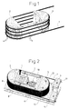
- the waveguide 1 illustrates a waveguide 1 in Shape of a quartz fiber wound on a core consisting of parts 2 and 3, whose distance a can be changed by means of a drive, not shown is.
- the core parts 2 and 3 each form half of a cylindrical body, so that the waveguide 1 has curved sections 4 with which it is on Core rests and substantially straight sections 5, the are formed between the core parts 2 and 3.
- the waveguide 1 is included its ends and in addition in the area of the curved sections 4 connected to the core parts 2 and 3 so that by changing the Distance a only the straight sections 5 of the waveguide 1 can be loaded or relieved of tension.
- the waveguide is under tension wound up the core, ensuring that the straight sections 5 are always excited.
- the waveguide 1 follows this movement by stretching the straight-line sections 5.
- the Distance change ⁇ a multiplied by twice the number of windings (Doubling since the straight sections 5 twice in each winding are present), in this case eight times the change in distance Corresponds to ⁇ a.
- a large number of windings can be wound onto the core, so that there is already a very considerable change in length of the waveguide 1 then results if the distance between the core parts 2 and 3 is only slight changes.
- a change in the distance is sufficient Core parts 2 and 3 of 45 ⁇ if the distance a is 80 mm and 23 windings are provided. If you use a core diameter of 30 mm, this results in a total length of the waveguide 1 of 5.50 m.
- Fig. 2 is such a device built on a base plate 6.
- A is firmly connected to the base plate Core part 3, whereas the left core part 2 in FIG. 2 has a not shown Solid body joint is linearly displaceable on the base plate 6.
- the Core parts 2 and 3 have, as in the basic illustration according to FIG. 1, semi-cylindrical Forms, however, the core part 3 is a U-shaped in plan view Guide part 7 of the rectilinear sections 5 of the form of a Quartz fiber trained waveguide 1 leads.
- This guide part 7 lies with little play on these sections 5 and should prevent them in dynamic operation swing transverse to the direction of the change in distance.
- the Guide part 7 can, however, also be subject to friction on the straight-line sections the quartz fiber in order to specifically achieve increased damping.
- the core parts 3 and 7 are by means of screws, not shown, on the Base plate 6 attached.
- a cuboid part closes on the left half-cylindrical core part 2 8 on, which protrudes inside the guide part 7 and part of a capacitive Path measuring device between the movable component 8 and a fixed one Component 9 is.
- the piezoelectric element 10 can consist of several in succession and / or individual elements arranged in parallel.
- the quartz fiber 1 is wound in one layer over the core 2, 3, 7, the Quartz fiber 1 in the region of its curved sections 4 on the core parts 2 and 3 is tight, whereas in the area of the straight sections 5 a loose System on the sides of the guide part 7, so that the quartz fiber in stretch these straight sections 5 freely and contract them again can.
- the quartz fiber 1 is fixed at the end, by means of two clamping plates 11, which are connected to the base plate 6. The winding up takes place under tension.
- the piezoelectric element 10 As soon as the piezoelectric element 10 is subjected to voltage, it expands this in the axial direction, whereby the core parts 2 and 3 away from each other be moved (distance change ⁇ a), causing an expansion of the straight line Sections 5 of the quartz fiber takes place. Since the movement, i.e. H. the temporal Course of the change in distance is detected by means of the path measuring device 8, 9, can the piezoelectric over a control not described in detail here Element 10 are controlled so that a predetermined path or Speed profile is generated. In any case, the change in distance ⁇ a and thus the change in length of the quartz fiber 1 can be determined exactly.
- the movable part 3 is reset on the one hand via the spring action of the solid-state joint and on the other hand via the restoring force of the quartz fiber 1.
- the device is particularly suitable for dynamic operation, the piezoelectric element 10 is for this purpose with a frequency in the range of Self-response stimulated.
- FIG. 3 shows how the above-described device in a interferometric measuring arrangement can be used.
- This arrangement consists of a light source 13 in the form of a laser, the light in a Quartz fiber 14 is fed, which opens into a first coupling device 15 and is passed there into a quartz fiber 16 and a quartz fiber 17.
- the Quartz fiber 16 forms part of the sample branch of the interferometric measuring arrangement and is similar to the embodiment described with reference to FIG. 2 two mutually movable core parts 2 and 3 wound, the distance is mutually changeable.
- the end of the quartz fiber 16 opens into an optical one Lens arrangement 18, which is in front of a sample 19 to be examined is arranged.
- the quartz fiber 17 is also wound on a core whose core parts 2 and 3 are adjustable in their distance from each other.
- the quartz fiber 17 forms the reference branch of the interferometric measuring arrangement. About the change in distance the core parts 2 and 3 can set the operating point of the arrangement become.
- the quartz fiber 17 opens into a second coupling device 20, in which also includes a quartz fiber 21 coming from the first coupling device 15 which emits the light reflected from the quartz fiber 16 by the sample 19 forwards that within the second coupling device 20 with that from the Glass fiber 17 coming light from the reference branch, thus ultimately the light source 13, is superimposed.
- the output of the second coupling device 20 is provided with two detectors 22 (light intensity / current converter), via which then the electrical evaluation of the optical signals takes place.
- a special feature of the arrangement shown in Fig. 3 is a heat conductive Plate 23 with which the core parts 2 and 3 of both the quartz fiber 16 and the Quartz fiber 17 are thermally connected.
- the core parts 2 and 3 can also be taken by suitable other measures can be brought about and has the advantageous effect that the measuring arrangement works practically independent of temperature because of a temperature-related change in length the quartz fiber 17 also requires one of the quartz fiber 16, the same Length and number of turns required.
Abstract
Die Vorrichtung dient zur Veränderung der Länge der Laufstrecke einer elektromagnetischen Welle. Sie weist einen Wellenleiter (1) auf, der auf einen Kern (2, 3) aufgewickelt ist. Der Kern (2, 3) ist zweiteilig ausgebildet, wobei der Abstand (a) der Kernteile (2 und 3) zueinander veränderbar ist, um den Wellenleiter (1) definiert zu dehnen. <IMAGE>The device is used to change the length of the path of an electromagnetic wave. It has a waveguide (1) which is wound on a core (2, 3). The core (2, 3) is formed in two parts, the distance (a) of the core parts (2 and 3) from one another being variable in order to stretch the waveguide (1) in a defined manner. <IMAGE>
Description
Die Erfindung betrifft eine Vorrichtung zur Veränderung der Länge der Laufstrecke einer elektromagnetischen Welle gemäß den im Oberbegriff des Anspruchs 1 angegebenen Merkmalen.The invention relates to a device for changing the length of the Running distance of an electromagnetic wave according to the in the preamble of claim 1 specified features.
Vorrichtungen dieser Art sind bekannt und dienen zur Laufzeitveränderung einer elektromagnetischen Welle, insbesondere eines Lichtstrahls, zur Erzeugung einer Doppler-Verschiebung, zur Erzeugung eines zeitabhängigen Spektrums oder dergleichen. Sie werden beispielsweise bei der optischen Kohärenztomographie (OCT), in Fasergyroskopen oder auch bei der Fouriertransformspektroskopie eingesetzt. Derartige Vorrichtungen sind überall dort einsetzbar, wo es erforderlich ist, die optische Weglänge eines Strahlengangs zu verändern.Devices of this type are known and are used to change the runtime an electromagnetic wave, in particular a light beam, to generate a Doppler shift, to generate a time-dependent Spectrum or the like. For example, you will be at optical coherence tomography (OCT), in fiber gyroscopes or also used in Fourier transform spectroscopy. Such devices can be used wherever it is required, the optical To change the path length of a beam path.
Bekannte Vorrichtungen arbeiten entweder mit Spiegelanordnungen oder aber, wie die hier in Rede stehenden, mit einem Wellenleiter, insbesondere einer Quarzfaser, deren Länge durch Dehnen des Leiters bzw. der Faser verändert wird.Known devices either work with mirror arrangements or, like the ones in question here, with a waveguide, especially a quartz fiber, the length of which is stretched by the conductor or the fiber is changed.
In US-PS 5,321,501 ist ein Gerät für die optische Kohärenztomographie beschrieben, das eine solche Vorrichtung beinhaltet. Diese Vorrichtung weist einen faseroptischen Wellenleiter auf, der um ein Piezoelement gewickelt ist, das sich bei Anlegen einer elektrischen Spannung dehnt, wodurch sich auch der darauf aufgewickelte Wellenleiter dehnt, wodurch sich die Laufstrecke des Lichts ändert. Ein Nachteil der dort beschriebenen Vorrichtung ist, dass die aufgrund der piezoelektrischen Ausdehnung erfolgte Dehnung des faseroptischen Leiters nicht definiert und mehrachsig erfolgt, wodurch spannungsinduzierte Doppelbrechung auftreten kann, was zur Verfälschung der Ergebnisse führt. Darüber hinaus neigt die dort beschriebene Vorrichtung im dynamischen Betrieb zu Partialschwingungen, was deren Brauchbarkeit in Frage stellt.In U.S. Patent 5,321,501 there is an apparatus for optical coherence tomography described, which includes such a device. This device has a fiber optic waveguide that wraps around a piezo element is wound, which expands when an electrical voltage is applied, which also causes the waveguide wound on it to expand the path of the light changes. A disadvantage of those described there Device is that due to the piezoelectric Expansion of the fiber optic conductor was not defined and multi-axis, which causes stress-induced birefringence can occur, which leads to falsification of the results. About that In addition, the device described there tends in dynamic operation to partial vibrations, which questions their usefulness.
Aus JP 600 63 517 ist ein ähnlicher Fasenmodulator bekannt, bei dem piezoeelektrische Elemente zu vier Seiten eines im Wesentlichen zylindrischen Körpers angeordnet sind, die gleichzeitig ansteuerbar sind. Bei dieser Anordnung kann zwar eine vergleichsweise hohe Dehnung erzielt werden, jedoch erfolgt die Dehnung undefiniert und mehrachsig, so dass ihr ebenfalls die vorgenannten Nachteile anhaften.A similar chamfer modulator is known from JP 600 63 517, in which Piezoelectric elements on four sides of a substantially cylindrical one Body are arranged, which can be controlled at the same time. at this arrangement can achieve a comparatively high elongation are, however, the stretching is undefined and multiaxial, so that you also have the aforementioned disadvantages.
Das Problem der Partizialschwingungen ist erkannt worden. In US-PS 5,101,449 ist eine Anordnung getroffen, bei der im Piezoelement exzentrisch eine Ausnehmung vorgesehen ist, um diese nachteiligen Effekte zu vermindern. Auch aus US-PS 5,493,623 ist eine Vorrichtung bekannt, welche diese Effekte vermindern soll, insbesondere die Anfälligkeit gegen Resonanzen.The problem of partial vibrations has been recognized. In U.S. PS 5,101,449 an arrangement is made in which is eccentric in the piezo element a recess is provided to these adverse effects Reduce. A device is also known from US Pat. No. 5,493,623, which is intended to reduce these effects, especially the vulnerability against resonance.
In US-PS 5,867,268 ist ein Gerät für die optische Kohärenztomographie beschrieben, bei der ein Lichtwellenleiter spiralförmig auf ein scheibenförmiges Piezoelement aufgeklebt ist. Aus US-PS 5,029,978 ist eine Vorrichtung bekannt, bei der die Lichtwellenleiter in ein piezoelektrisch aktives Polymer eingegossen sind. In der US-PS 5,135,295 ist beschrieben, eine optische Faser mit einem piezoelektrisch aktivem Material zu ummanteln, um auf diese Weise die Faser praktisch unmittelbar strecken zu können.US Pat. No. 5,867,268 discloses an apparatus for optical coherence tomography described in which an optical waveguide spirally on a disc-shaped Piezo element is glued on. A device is known from US Pat. No. 5,029,978 known in which the optical fiber in a piezoelectric active polymer are cast. US Pat. No. 5,135,295 describes to coat an optical fiber with a piezoelectrically active material, to stretch the fiber almost immediately in this way can.
All den vorerwähnten Vorrichtungen gemeinsam ist, dass die optische Phasenverschiebung über eine an ein Piezoelement angelegte Spannung verändert wird. Die an das Piezoelement angelegte Spannung ist aber nur in erster Näherung proportional zu dessen Längenänderungen, weil Piezoelemente systembedingt ein nichtlineares Ausdehnungsverhalten haben. Bei dynamischer Ansteuerung, d. h. bei Ansteuerung mit einer sich periodisch ändernden Spannung neigen Piezoelemente bei bestimmten Eigenfrequenzen zu Resonanzen. Bei bestimmten Anwendungen für optische Phasenmodulatoren ist es notwendig, die genaue Weglängenänderung des Phasenmodulators zu kennen, um das nichtlineare Verhalten der Piezoelemente rechnerisch kompensieren zu können oder auch um einen Regelkreis aufbauen zu können, um eine gewünschte Wegänderung herbeizuführen.All of the above-mentioned devices have in common that the optical Phase shift via a voltage applied to a piezo element is changed. The voltage applied to the piezo element is but only in a first approximation proportional to its length changes, because piezo elements have a non-linear expansion behavior due to the system to have. With dynamic control, i.e. H. when activated with Piezo elements tend to a periodically changing voltage certain natural frequencies to resonances. For certain applications for optical phase modulators it is necessary to determine the exact Knowing the path length change of the phase modulator to the nonlinear Computationally compensate for the behavior of the piezo elements can or to be able to build a control loop to a bring about the desired path change.
Vor diesem Stand der Technik liegt der Erfindung die Aufgabe zugrunde, eine gattungsgemäße Vorrichtung so auszugestalten, dass die vorerwähnten Nachteile weitgehend vermieden werden und dass insbesondere eine definierte Weglängenänderung erzielbar ist, die ggf. auch messtechnisch erfasst werden kann.In view of this prior art, the object of the invention is to design a generic device so that the aforementioned Disadvantages are largely avoided and that in particular a defined path length change can be achieved, which may can also be measured.
Diese Aufgabe wird gemäß der Erfindung durch die in Anspruch 1 angegebenen Merkmale gelöst. Vorteilhafte Ausgestaltungen ergeben sich aus den Unteransprüchen, der nachfolgenden Beschreibung und der Zeichnung.This object is achieved according to the invention by those specified in claim 1 Features solved. Advantageous configurations result from the dependent claims, the description below and the Drawing.
Grundgedanke der vorliegenden Erfindung ist es, die Dehnung des Wellenleiters nur dort herbeizuführen, wo dieser im Wesentlichen geradlinig verläuft, um eine definierte Längenänderung unter Vermeidung der eingangs genannten Nachteile sicher zu stellen. Der Wellenleiter wird dabei auf einen geteilten mehrteiligen Kern aufgewickelt und die Längenänderung durch Abstandsänderung der Kernteile zueinander bewirkt. In einfachster Form kann dies dadurch geschehen, dass der Kern aus zwei Hälften gebildet wird, deren Abstand zueinander veränderbar ist. Auf diese Weise ist es möglich, den Wellenleiter in seinen geradlinigen Abschnitten zwischen diesen Hälften nahezu ausschließlich mit Zugkräften zu beaufschlagen, um eine definierte Längenänderung zu erzielen. Dabei kann praktisch jeder beliebige Antrieb zum Dehnen eingesetzt werden. Auch ist eine Erfassung der Längenänderung ohne weiteres möglich, in dem die Abstandsänderung der Hälften zueinander ermittelt wird.The basic idea of the present invention is to stretch the Only bring the waveguide where it is essentially straight runs to avoid a defined change in length to ensure disadvantages mentioned above. The waveguide will thereby wound on a divided multi-part core and the change in length by changing the distance between the core parts causes. In the simplest form, this can be done by the Core is formed from two halves, the distance between which can be changed is. This way it is possible to insert the waveguide in its rectilinear sections between these halves almost exclusively to apply tensile forces to a defined change in length to achieve. Practically any drive for stretching can be used be used. A detection of the change in length is also without further possible in which the distance change of the halves to each other is determined.
Grundsätzlich ist es denkbar, die Hälften bzw. die Kernteile zueinander um eine Achse zu verschwenken, um dadurch eine Lageänderung herbeizuführen. Bevorzugt wird die Lageänderung jedoch durch eine Linearverschiebung der Kernteile zueinander erfolgen, da dann sichergestellt werden kann, dass bei geeigneter Anordnung der Windungen sowie Ausgestaltung der Kerne ausschließlich Zugspannungen auf die Wellenleiter aufgebracht werden. Hierdurch können die sonst so nachteiligen spannungsinduzierten Doppelbrechungen vermieden werden. Dabei spielt es prinzipiell keine Rolle, ob beide Kernteile oder auch mehrere Kernteile zueinander bewegt werden oder ob nur ein Kernteil von dem anderen bzw. den übrigen Kernteilen bewegt wird. Die Dehnung kann dabei durch ein Piezoelement, durch ein Stack von Piezoelementen, elektromagnetisch, elektromotorisch (mit einem Exzentertrieb) oder einem anderen geeigneten Antrieb erfolgen, ohne das erfindungsgemäße Prinzip zu verlassen.In principle, it is conceivable for the halves or the core parts to be in relation to one another to pivot about an axis, thereby changing the position bring about. However, the change in position is preferred by Linear displacement of the core parts to each other take place, since this ensures can be that with a suitable arrangement of the turns as well as design of the cores exclusively tensile stresses on the Waveguides are applied. This can otherwise be disadvantageous stress-induced birefringence can be avoided. In principle, it does not matter whether both core parts or also several core parts are moved towards each other or whether only one core part is moved by the other or the other core parts. The stretch can by a piezo element, by a stack of piezo elements, electromagnetic, electromotive (with an eccentric drive) or another suitable drive without the leave principle according to the invention.
Um vorwiegend Zugspannungen im Wellenleiter zu erzeugen, ist es zweckmäßig, den zu bewegenden Kernteil bzw. die zu bewegenden Kernteile entsprechend zu lagern. Dies kann beispielsweise durch eine Linearführung, z. B. eine Wälzlagerführung, mittels einer Gleitlagerführung oder auch mittels einer pneumatischen oder hydraulischen Führung erfolgen. Vorteilhaft kann hier auch ein Festkörpergelenk eingesetzt werden, beispielsweise eine Parallelblattfederführung.In order to generate predominantly tensile stresses in the waveguide, it is expedient, the core part to be moved or to be moved Store core parts accordingly. This can be done, for example, by a Linear guide, e.g. B. a roller bearing guide, by means of a plain bearing guide or by means of a pneumatic or hydraulic guide respectively. A solid-state joint can also advantageously be used here are, for example, a parallel leaf spring guide.
Besonders zweckmäßig ist es, wenn der Kern Abschnitte aufweist, längs derer der Wellenleiter gekrümmt und andere Abschnitte, längs derer der Wellenleiter im Wesentlichen geradlinig verläuft und der Wellenleiter in den Bereichen, in denen er gekrümmt verläuft, auf dem zugehörigen Kernabschnitt festgeklebt oder in anderer geeigneter Weise stoff- oder kraftschlüssig befestigt ist, damit sichergestellt ist, dass in diesen Bereichen keine oder eine nur geringe Relativbewegung zwischen Kern und Wellenleiter erfolgt, sondern nur in den Bereichen, in denen der Wellenleiter geradlinig verläuft. In letzteren Bereichen sollte der Wellenleiter vorzugsweise nicht unmittelbar oder wenn nur mit möglichst geringem Reibungskoeffizienten anliegen, um keine Querkräfte neben den Zugspannungen einzuleiten. Andererseits bringt eine solche Stützung der im Wesentlichen geradlinig verlaufenden Abschnitte des Wellenleiters erhebliche Vorteile mit sich, insbesondere im dynamischen Betrieb, da dann ein unkontrolliertes Schwingen des Wellenleiters in diesen Bereichen verhindert werden kann.It is particularly expedient if the core has sections, lengthways of which the waveguide is curved and other sections along which the Waveguide runs essentially straight and the waveguide in the areas in which it is curved, on the corresponding one Core section glued or in some other suitable material or is non-positively attached to ensure that in these areas little or no relative movement between core and Waveguide occurs, but only in the areas where the waveguide runs straight. In the latter areas, the waveguide should preferably not immediately or if only with as little as possible Friction coefficients are applied in order to avoid any transverse forces in addition to the tensile stresses initiate. On the other hand, such support brings in Essentially rectilinear sections of the waveguide considerable advantages, especially in dynamic operation, because then an uncontrolled oscillation of the waveguide in these areas can be prevented.
Besonders vorteilhaft ist es, wenn die Kernabschnitte, in denen der Wellenleiter gekrümmt verläuft, durch Hälften eines zylindrischen Körpers gebildet sind, der längs seiner Achse geteilt ist. Im übrigen Bereich zwischen diesen Zylinderhälften sind zweckmäßigerweise Führungen vorgesehen, welche ein Querschwingen des Wellenleiters verhindern oder zumindest dämpfen.It when the core sections in which the Waveguide is curved, through halves of a cylindrical body are formed, the is divided along its axis. In the remaining area between these cylinder halves guides are expediently provided which have a transverse swing prevent or at least attenuate the waveguide.
Bei der erfindungsgemäßen Vorrichtung kann bevorzugt auch ein Piezoelement oder ein Stack von Piezoelementen als Antrieb Verwendung finden, da das nichtlineare Verhalten entweder durch eine entsprechende Regelung oder messtechnisch kompensiert werden kann. Hierzu ist parallel zum Antrieb, z. B. zwischen den zueinander beweglichen Kernabschnitten, ein Messwertaufnehmer vorzusehen, vorzugsweise ein kapazitiver Aufnehmer. Es können aber auch je nach Art und Umfang der Dehnungen beliebige andere Messwertaufnehmer, z.B. Dehnungsmessstreifen (DMS), induktive Aufnehmer oder dergleichen eingesetzt werden.In the device according to the invention, a piezo element can preferably also be used or a stack of piezo elements can be used as the drive, since that nonlinear behavior either through appropriate regulation or can be compensated for by measurement. For this purpose, parallel to the drive, e.g. B. between the mutually movable core sections, a sensor provide, preferably a capacitive transducer. But it can also ever any other transducers depending on the type and extent of the strains, e.g. Strain gauges, inductive sensors or the like be used.
Als Wellenleiter kann vorteilhaft Quarzfaser eingesetzt werden, wobei je nach Anforderungen schutzummantelte oder auch nicht schutzummantelte Quarzfaser Verwendung finden kann. Derartige Quarzfasern sind kostengünstig herzustellen und können bis zu 10 % elastisch gedehnt werden, so dass schon bei geringer Wicklungszahl große Längenänderungen erreicht werden können. Bevorzugt erfolgt die Wicklung einlagig, es können jedoch auch mehrlagige Wicklungen vorgesehen sein, wenn sichergestellt wird, dass der Wellenleiter im Bereich seiner gekrümmten Abschnitte festgelegt wird, um mehrachsige Spannungseinleitungen zu vermeiden.Quartz fiber can advantageously be used as the waveguide, depending on Requirements of protective or non-protective quartz fiber Can be used. Such quartz fibers are inexpensive to manufacture and can be stretched up to 10% elastically, so that even at low Number of turns large changes in length can be achieved. Prefers the winding takes place in one layer, but multi-layer windings can also be used be provided if it is ensured that the waveguide is in the area its curved sections is set to multi-axis voltage injections to avoid.
Bevorzugt weist die Vorrichtung eine Regelung auf, welche in Abhängigkeit des vom Wegaufnehmer (Messwertaufnehmer) abgegebenen Signals das den Abstand der Kernteile bestimmende Antriebselement steuert, so dass die Längenänderung der Laufstrecke gezielt veränderbar ist, insbesondere auch in Abhängigkeit der Zeit. Auf diese Weise kann die Längenänderung nach einem vorgegebenen Geschwindigkeits- oder Wegprofil erfolgen. The device preferably has a control system which is a function of the the signal emitted by the displacement transducer (measuring transducer) is the distance of the core parts determining drive element controls so that the change in length the running route can be changed in a targeted manner, in particular also depending currently. In this way, the change in length according to a predetermined Speed or path profile.
Bei Einsatz eines Piezoelements als Antrieb kann es vorteilhaft sein, dieses im Resonanzbereich zu betreiben, da dann die Kraftentfaltung, d. h. also der Wirkungsgrad besonders hoch ist. Darüber hinaus arbeitet die Vorrichtung in diesem Bereich sehr frequenzstabil.When using a piezo element as the drive, it can be advantageous to do this in the Operate resonance range, because then the power delivery, i.e. H. so the efficiency is particularly high. In addition, the device works in this Very stable frequency range.
Ein bevorzugter Einsatzzweck der erfindungsgemäßen Vorrichtung ist bei der Fouriertransformspektroskopie, und zwar im Probenzweig. Auch kann die Vorrichtung als Phasenmodulator wahlweise im Referenz- und/oder im Probenzweig eines Interferometers eingesetzt werden, das bei der optischen Kohärenztomographie eingesetzt wird. Eine solche interferometrische Messanordnung kann beispielsweise zwei Koppeleinrichtungen aufweisen, wobei in einer ersten Koppeleinrichtung die von einer Lichtquelle kommenden Lichtwellen in einen Probenarm und in einen Referenzarm eingekoppelt werden und in der zweiten Koppeleinrichtung die vom Referenzarm kommenden Lichtwellen sowie die vom Probenarm kommenden Lichtwellen überlagert und mindestens einem, vorzugsweise zwei Detektoren zugeführt werden, welche die optische Interferenz in ein elektrisches Signal umwandeln. Bei dieser Anordnung ist der Referenzarm durch einen sich zwischen den Koppeleinrichtungen erstreckenden Faserleiter gebildet. Der Probenarm weist vorzugsweise mindestens zwei Faserleiter auf, die sich zu beiden Seiten der ersten Koppeleinrichtung erstrecken. Eine solche Anordnung ist besonders lichtstark und aufgrund ihres Aufbaus (Führung der Lichtwellen nahezu ausschließlich in Faserleitern) weitgehend unempfindlich gegen äußere Umgebungseinflüsse. Über das freie Ende des Probenarms kann darüber hinaus die Topologie eines externen Objektes eingebunden werden, wie es beispielsweise bei der Fourier-Transformspektroskopie erfolgt. Vorteilhaft wird die erfindungsgemäße Vorrichtung sowohl im Probenzweig als auch im Referenzzweig eines Interferometers eingesetzt, wobei eine Vorrichtung zur dynamischen Weglängenänderung des Lichts und die andere zur statischen Einstellung des Arbeitspunktes dient. Dabei können in vorteilhafter Ausgestaltung der Erfindung beide Vorrichtungen thermisch, beispielsweise durch ein wärmeleitendes gemeinsames Traggestell miteinander verbunden sein, wodurch sichergestellt wird, dass auch bei sich ändernder Betriebstemperatur keine nach außen in Erscheinung tretende Verschiebung des Arbeitspunktes bzw. eine entsprechende Verschiebung auch im anderen Zweig erfolgt, die dies kompensiert.A preferred application of the device according to the invention is in the Fourier transform spectroscopy, in the sample branch. It can also Device as a phase modulator either in the reference and / or in the sample branch an interferometer used in optical coherence tomography is used. Such an interferometric measuring arrangement can have, for example, two coupling devices, one in a first Coupling device the light waves coming from a light source into one Sample arm and be coupled into a reference arm and in the second Coupling device the light waves coming from the reference arm and the light waves coming from the sample arm are superimposed and at least one, preferably two detectors are supplied, which the optical interference convert into an electrical signal. In this arrangement, the reference arm by one extending between the coupling devices Fiber conductor formed. The sample arm preferably has at least two Fiber conductors on both sides of the first coupling device extend. Such an arrangement is particularly bright and because of its Construction (guidance of the light waves almost exclusively in fiber guides) largely insensitive to external environmental influences. About the free end the topology of an external object be involved, as is the case with Fourier transform spectroscopy, for example he follows. The device according to the invention is advantageous both in Sample branch and also used in the reference branch of an interferometer, where a device for dynamic path length change of light and the other serves for the static setting of the working point. You can in advantageous embodiment of the invention, both devices thermally, for example, by means of a heat-conducting common support frame be connected, thereby ensuring that even with changing Operating temperature no outward shift of the Working point or a corresponding shift in the other branch takes place, which compensates for this.
Aufgrund der definierten Längenänderung bzw. der einfachen Erfassbarkeit der Längenänderung kann die erfindungsgemäße Vorrichtung in vielen Bereichen eingesetzt werden, beispielsweise zur Feldstärkemessung unter Ausnutzung des elektrostriktiven Effekts.Due to the defined change in length or the easy comprehensibility of the The device according to the invention can change length in many areas are used, for example for field strength measurement using the electrostrictive effect.
Die Erfindung ist nachfolgend anhand eines in der Zeichnung dargestellten Ausführungsbeispiels erläutert. Es zeigen:
- Fig. 1
- in stark vereinfachter schematischer Darstellung das Prinzip der vorliegenden Erfindung,
- Fig. 2
- in perspektivischer Darstellung ein Ausführungsbeispiel einer Vorrichtung gemäß der Erfindung und
- Fig. 3
- in schematischer Prinzipdarstellung die Anwendung der erfin dungsgemäßen Vorrichtung bei einem Interferometer.
- Fig. 1
- the principle of the present invention in a highly simplified schematic representation,
- Fig. 2
- in perspective an embodiment of a device according to the invention and
- Fig. 3
- a schematic representation of the principle of the application of the device according to the invention in an interferometer.
Wie die Prinzipdarstellung nach Fig. 1 veranschaulicht, ist ein Wellenleiter 1 in
Form einer Quarzfaser auf einen aus Teilen 2 und 3 bestehenden Kern aufgewickelt,
deren Abstand a mittels eines nicht dargestellten Antriebs veränderbar
ist. Die Kernteile 2 und 3 bilden jeweils die Hälfte eines zylindrischen Körpers,
so dass der Wellenleiter 1 gekrümmte Abschnitte 4 aufweist, mit denen er am
Kern anliegt sowie im Wesentlichen geradlinig verlaufende Abschnitte 5, die
zwischen den Kernteilen 2 und 3 gebildet sind. Dabei ist der Wellenleiter 1 mit
seinen Enden festgelegt und darüber hinaus im Bereich der gekrümmten Abschnitte
4 so mit den Kernteilen 2 und 3 verbunden, dass durch Änderung des
Abstandes a lediglich die geradlinig verlaufenden Abschnitte 5 des Wellenleiters
1 zugbelastet bzw. -entlastet werden. Der Wellenleiter ist unter Vorspannung auf
dem Kern aufgewickelt, so dass sichergestellt ist, dass die geradlinigen Abschnitte
5 stets gespannt sind. Wird nun der Abstand a zwischen den Kernteilen
2 und 3 um eine Länge Δa vergrößert, so folgt der Wellenleiter 1 dieser Bewegung
durch Dehnung der geradlinigen Abschnitte 5. Bei dem anhand von Fig. 1
dargestellten Beispiel, bei dem der Wellenleiter 1 in vier Wicklungen aufgewickelt
ist, ergibt sich somit eine Längenänderung des Wellenleiters 1, die der
Abstandsänderung Δa multipliziert mit dem Zweifachen der Wicklungszahl
(Verdopplung, da die geradlinigen Abschnitte 5 in jeder Wicklung zweimal
vorhanden sind), im vorliegenden Fall also im Achtfachen der Abstandsänderung
Δa entspricht. Bei Verwendung von marktüblichen Quarzfasern als Wellenleiter
kann eine Vielzahl von Wicklungen auf den Kern aufgewickelt werden,
so dass sich eine ganz erhebliche Längenänderung des Wellenleiters 1 schon
dann ergibt, wenn man den Abstand der Kernteile 2 und 3 nur geringfügig
ändert.1 illustrates a waveguide 1 in
Shape of a quartz fiber wound on a core consisting of
Um beispielsweise eine für die optische Kohärenztomographie erforderliche
Weglängenänderung von 2 mm zu erreichen, genügt eine Abstandsänderung der
Kernteile 2 und 3 von 45 µ, wenn der Abstand a 80 mm beträgt und 23 Wicklungen
vorgesehen sind. Legt man einen Kerndurchmesser von 30 mm zugrunde,
dann ergibt sich eine Gesamtlänge des Wellenleiters 1 von 5,50 m.For example, one required for optical coherence tomography
To achieve a path length change of 2 mm, a change in the distance is
Bei dem in Fig. 2 dargestellten Ausführungsbeispiel ist eine solche Vorrichtung
auf einer Grundplatte 6 aufgebaut. Fest mit der Grundplatte verbunden ist ein
Kernteil 3, wohingegen der in Fig. 2 linke Kernteil 2 über ein nicht dargestelltes
Festkörpergelenk linear verschiebbar auf der Grundplatte 6 angeordnet ist. Die
Kernteile 2 und 3 weisen wie bei der Prinzipdarstellung nach Fig. 1 halbzylindrische
Formen auf, jedoch schließt sich an den Kernteil 3 ein in Draufsicht uförmiger
Führungsteil 7 an, der die geradlinigen Abschnitte 5 des in Form einer
Quarzfaser ausgebildeten Wellenleiters 1 führt. Dieser Führungsteil 7 liegt mit
geringem Spiel an diesen Abschnitten 5 an und soll verhindern, dass diese im
dynamischen Betrieb quer zur Richtung der Abstandsänderung schwingen. Der
Führungsteil 7 kann jedoch auch reibungsbehaftet an den geradlinigen Abschnitten
der Quarzfaser anliegen, um gezielt eine erhöhte Dämpfung zu bewirken.
Die Kernteile 3 und 7 sind mittels nicht dargestellter Schrauben auf der
Grundplatte 6 befestigt.In the embodiment shown in Fig. 2 is such a device
built on a
An den linken halbzylindrischen Kernteil 2 schließt sich ein quaderförmiger Teil
8 an, der in den Führungsteil 7 innen hineinragt und Teil einer kapazitiven
Wegmesseinrichtung zwischen dem beweglichen Bauteil 8 und einem feststehenden
Bauteil 9 ist.A cuboid part closes on the left half-
Zwischen den Kernteilen 2 und 3 ist ein piezoelektrisches Element 10 als
Antrieb vorgesehen, das sich an der Innenseite des Führungsteils 7 einerseits
sowie an der gegenüberliegenden Seite des quaderförmigen Teils 8 andererseits
abstützt. Das piezoelektrische Element 10 kann aus mehreren hintereinander
und/oder parallel angeordneten Einzelelementen aufgebaut sein.Between the
Die Quarzfaser 1 ist einlagig über dem Kern 2, 3, 7 aufgewickelt, wobei die
Quarzfaser 1 im Bereich ihrer gekrümmten Abschnitte 4 an den Kernteilen 2 und
3 fest anliegt, wohingegen im Bereich der geradlinigen Abschnitte 5 eine lose
Anlage an den Seiten des Führungsteils 7 besteht, so dass sich die Quarzfaser in
diesen geradlinigen Abschnitten 5 frei dehnen und auch wieder zusammenziehen
kann. Endseitig ist die Quarzfaser 1 festgelegt, und zwar mittels zweier Klemmplatten
11, die mit der Grundplatte 6 verbunden sind. Die Aufwicklung erfolgt
unter Vorspannung.The quartz fiber 1 is wound in one layer over the
Sobald das piezoelektrische Element 10 spannungsbeaufschlagt wird, dehnt sich
dieses in Achsrichtung aus, wodurch die Kernteile 2 und 3 voneinander weg
bewegt werden (Abstandsänderung Δa), wodurch eine Dehnung der geradlinigen
Abschnitte 5 der Quarzfaser erfolgt. Da die Bewegung, d. h. der zeitliche
Verlauf der Abstandsänderung mittels der Wegmesseinrichtung 8, 9 erfasst wird,
kann über eine hier nicht im Einzelnen beschriebene Regelung das piezoelektrische
Element 10 so angesteuert werden, dass ein vorbestimmtes Weg- oder
Geschwindigkeitsprofil erzeugt wird. In jedem Falle ist die Abstandsänderung
Δa und damit die Längenänderung der Quarzfaser 1 exakt ermittelbar. Die
Rückstellung des beweglichen Teils 3 erfolgt zum einen über die Federwirkung
des Festkörpergelenks und zum anderen über die Rückstellkraft der Quarzfaser
1. Die Vorrichtung ist insbesondere auch zum dynamischen Betrieb geeignet,
das piezoelektrische Element 10 wird hierzu mit einer Frequenz im Bereich der
Eigenresonanz angeregt.As soon as the
Anhand von Fig. 3 ist dargestellt, wie die vorbeschriebene Vorrichtung in einer
interferometrischen Messanordnung eingesetzt werden kann. Diese Anordnung
besteht aus einer Lichtquelle 13 in Form eines Lasers, dessen Licht in eine
Quarzfaser 14 eingespeist ist, die in einer ersten Koppeleinrichtung 15 mündet
und dort in eine Quarzfaser 16 sowie eine Quarzfaser 17 geleitet wird. Die
Quarzfaser 16 bildet Teil des Probenzweiges der interferometrischen Messanordnung
und ist ähnlich der anhand von Fig. 2 beschriebenen Ausführung auf
zwei zueinander bewegliche Kemteile 2 und 3 aufgewickelt, deren Abstand
zueinander änderbar ist. Das Ende der Quarzfaser 16 mündet in einer optischen
Linsenanordnung 18, die mit Abstand vor einer zu untersuchenden Probe 19
angeordnet wird.3 shows how the above-described device in a
interferometric measuring arrangement can be used. This arrangement
consists of a
Die Quarzfaser 17 ist ebenfalls auf einem Kern aufgewickelt, dessen Kernteile 2
und 3 in ihrem Abstand zueinander einstellbar sind. Die Quarzfaser 17 bildet
den Referenzzweig der interferometrischen Messanordnung. Über die Abstandsänderung
der Kernteile 2 und 3 kann der Arbeitspunkt der Anordnung eingestellt
werden. Die Quarzfaser 17 mündet in einer zweiten Koppeleinrichtung 20, in
der auch eine von der ersten Koppeleinrichtung 15 kommende Quarzfaser 21
mündet, welche das aus der Quarzfaser 16 von der Probe 19 reflektierte Licht
weiterleitet, das innerhalb der zweiten Koppeleinrichtung 20 mit dem aus der
Glasfaser 17 kommenden Licht des Referenzzweiges, also letztlich der Lichtquelle
13, überlagert wird. Der Ausgang der zweiten Koppeleinrichtung 20 ist
mit zwei Detektoren 22 (Lichtintensitäts-/Stromwandler) versehen, über welche
dann die elektrische Auswertung der optischen Signale erfolgt.The
Während die Kernteile 2 und 3, auf welche die Quarzfaser 17 aufgewickelt ist,
lediglich zur Einstellung des Arbeitspunktes in ihrem Abstand veränderbar sind,
weisen die Kernteile 2 und 3, auf denen die Quarzfaser 16 aufgewickelt ist,
einen Antrieb wie anhand von Fig. 2 dargestellt auf. Da das Licht die Glasfaser
16 sowohl auf dem Hinweg zur Probe 19 als auch auf dem Rückweg durchläuft,
geht jede Abstandsänderung der Kernteile 2 und 3 ungeachtet der Wicklungszahl
zusätzlich mit dem Faktor 2 ein.While the
Eine Besonderheit der in Fig. 3 dargestellten Anordnung ist eine wärmeleitende
Platte 23, mit der die Kernteile 2 und 3 sowohl der Quarzfaser 16 als auch der
Quarzfaser 17 wärmeleitend verbunden sind. Eine solche wärmeleitende Verbindung
der Kernteile 2 und 3 kann auch durch geeignete andere Maßnahmen
herbeigeführt werden und hat den vorteilhaften Effekt, dass die Messanordnung
praktisch temperaturunabhängig arbeitet, da eine temperaturbedingte Längenänderung
der Quarzfaser 17 auch eine solche der Quarzfaser 16 bedingt, gleiche
Länge und Wicklungszahlen vorausgesetzt. A special feature of the arrangement shown in Fig. 3 is a
- 1 -1 -
- Wellenleiter, QuarzfaserWaveguide, quartz fiber
- 2 -2 -
- linker Teil des Kernsleft part of the core
- 3 -3 -
- rechter Teil des Kernsright part of the core
- 4 -4 -
- gekrümmte Abschnitte von 1curved sections of 1
- 5 -5 -
- geradlinige Abschnitte von 1rectilinear sections of 1
- 6 -6 -
- Grundplattebaseplate
- 7 -7 -
- Führungsteilguide part
- 8 -8th -
- quaderförmiger Teilcuboid part
- 9 -9 -
- Wegmesseinrichtungdisplacement measuring system
- 10 -10 -
- piezoelektrisches Elementpiezoelectric element
- 11 -11 -
- Klemmplattenclamps
- 12 -12 -
- erste geradlinige Abschnitte von 1first straight sections of 1
- 13 -13 -
- Lichtquellelight source
- 14 -14 -
- Quarzfaserquartz fiber
- 15 -15 -
- erste Koppeleinrichtungfirst coupling device
- 16 -16 -
- Quarzfaserquartz fiber
- 17 -17 -
- Quarzfaserquartz fiber
- 18 -18 -
- Linsenanordnunglens assembly
- 19 -19 -
- Probesample
- 20 -20 -
- zweite Koppeleinrichtungsecond coupling device
- 21 -21 -
- Quarzfaserquartz fiber
- 22 -22 -
- Detektorendetectors
- 23 -23 -
- wärmeleitende Platteheat-conducting plate
- a -a -
- Abstanddistance
- Δa -Δa -
- Abstandsänderungdistance change
Claims (15)
Applications Claiming Priority (2)
| Application Number | Priority Date | Filing Date | Title |
|---|---|---|---|
| DE10035833A DE10035833A1 (en) | 2000-07-21 | 2000-07-21 | Device for changing the length of the path of an electromagnetic wave |
| DE10035833 | 2000-07-21 |
Publications (2)
| Publication Number | Publication Date |
|---|---|
| EP1174680A2 true EP1174680A2 (en) | 2002-01-23 |
| EP1174680A3 EP1174680A3 (en) | 2003-03-12 |
Family
ID=7649924
Family Applications (1)
| Application Number | Title | Priority Date | Filing Date |
|---|---|---|---|
| EP01117591A Withdrawn EP1174680A3 (en) | 2000-07-21 | 2001-07-20 | Device for varying the path length of an electromagnetic wave |
Country Status (3)
| Country | Link |
|---|---|
| US (1) | US6748128B2 (en) |
| EP (1) | EP1174680A3 (en) |
| DE (1) | DE10035833A1 (en) |
Families Citing this family (7)
| Publication number | Priority date | Publication date | Assignee | Title |
|---|---|---|---|---|
| WO2003090325A1 (en) * | 2002-04-19 | 2003-10-30 | Fujitsu Limited | (rare earth dope) fiber module, and manufacturing method thereof |
| DE102004028204B3 (en) * | 2004-06-09 | 2005-10-06 | Medizinisches Laserzentrum Lübeck GmbH | Method for signal evaluation in OCT |
| US7359586B2 (en) * | 2004-11-12 | 2008-04-15 | Gennadii Ivtsenkov | Fiber optic strain sensor and associated data acquisition system |
| US20100309750A1 (en) * | 2009-06-08 | 2010-12-09 | Dominic Brady | Sensor Assembly |
| US9061425B2 (en) * | 2013-10-15 | 2015-06-23 | Avago Technologies General Ip (Singapore) Pte. Ltd. | Frame transfer device for an optical strain gauge structure |
| EP3095251B1 (en) * | 2014-01-13 | 2020-07-29 | Deep Imaging Technologies Inc. | Fiber optic sensor for electromagnetic data collection |
| WO2016032517A1 (en) | 2014-08-29 | 2016-03-03 | Schlumberger Canada Limited | Fiber optic magneto-responsive sensor assembly |
Citations (3)
| Publication number | Priority date | Publication date | Assignee | Title |
|---|---|---|---|---|
| DE2364671A1 (en) * | 1973-12-24 | 1975-06-26 | Otto Huebner | Electric hair-dryer - has flexible tapering nozzle attached to hot air outlet opening of housing |
| US4609871A (en) | 1984-07-02 | 1986-09-02 | The United States Of America As Represented By The Secretary Of The Navy | Temperature compensated optical fiber interferometric magnetometer |
| US5321501A (en) | 1991-04-29 | 1994-06-14 | Massachusetts Institute Of Technology | Method and apparatus for optical imaging with means for controlling the longitudinal range of the sample |
Family Cites Families (15)
| Publication number | Priority date | Publication date | Assignee | Title |
|---|---|---|---|---|
| US4530603A (en) * | 1982-09-29 | 1985-07-23 | The Board Of Trustees Of Leland Stanford Jr. Univ. | Stabilized fiber optic sensor |
| JPS6063517A (en) * | 1983-09-16 | 1985-04-11 | Sumitomo Electric Ind Ltd | Phase modulator |
| US4671659A (en) * | 1985-11-08 | 1987-06-09 | Martin Marietta Corporation | Fiber optic displacement sensor |
| JPS63265173A (en) * | 1987-04-23 | 1988-11-01 | Sumitomo Electric Ind Ltd | Electric field sensor |
| US4799752A (en) * | 1987-09-21 | 1989-01-24 | Litton Systems, Inc. | Fiber optic gradient hydrophone and method of using same |
| US4893930A (en) * | 1988-01-25 | 1990-01-16 | The United States Of America As Represented By The Secretary Of The Navy | Multiple axis, fiber optic interferometric seismic sensor |
| GB2221999B (en) * | 1988-08-16 | 1992-09-16 | Plessey Co Plc | Optical phase modulator |
| US5135295A (en) * | 1990-02-27 | 1992-08-04 | Queen's University At Kingston | Fiber-optic piezoelectric devices |
| US5101449A (en) * | 1990-06-05 | 1992-03-31 | Matsushita Electric Industrial Co., Ltd. | Optical phase modulator with asymmetric piezoelectric vibrator |
| GB9026587D0 (en) * | 1990-12-06 | 1991-04-24 | Marconi Gec Ltd | Improvements relating to optical fibre coil assemblies |
| US5457532A (en) * | 1994-05-31 | 1995-10-10 | Honeywell Inc. | Harmonic phase modulation error reducer |
| US5493623A (en) * | 1994-06-28 | 1996-02-20 | Honeywell Inc. | PZT fiber optic modulator having a robust mounting and method of making same |
| RU2100787C1 (en) * | 1995-03-01 | 1997-12-27 | Геликонов Валентин Михайлович | Fibre-optical interferometer and fiber-optical piezoelectric transducer |
| US5552887A (en) * | 1995-04-07 | 1996-09-03 | Andrew Corporation | Fiber optic rotation sensor or gyroscope with improved sensing coil |
| US5625724A (en) * | 1996-03-06 | 1997-04-29 | Litton Systems, Inc | Fiber optic hydrophone having rigid mandrel |
-
2000
- 2000-07-21 DE DE10035833A patent/DE10035833A1/en not_active Withdrawn
-
2001
- 2001-07-20 EP EP01117591A patent/EP1174680A3/en not_active Withdrawn
- 2001-07-20 US US09/910,124 patent/US6748128B2/en not_active Expired - Fee Related
Patent Citations (3)
| Publication number | Priority date | Publication date | Assignee | Title |
|---|---|---|---|---|
| DE2364671A1 (en) * | 1973-12-24 | 1975-06-26 | Otto Huebner | Electric hair-dryer - has flexible tapering nozzle attached to hot air outlet opening of housing |
| US4609871A (en) | 1984-07-02 | 1986-09-02 | The United States Of America As Represented By The Secretary Of The Navy | Temperature compensated optical fiber interferometric magnetometer |
| US5321501A (en) | 1991-04-29 | 1994-06-14 | Massachusetts Institute Of Technology | Method and apparatus for optical imaging with means for controlling the longitudinal range of the sample |
Also Published As
| Publication number | Publication date |
|---|---|
| EP1174680A3 (en) | 2003-03-12 |
| DE10035833A1 (en) | 2002-02-07 |
| US6748128B2 (en) | 2004-06-08 |
| US20020126979A1 (en) | 2002-09-12 |
Similar Documents
| Publication | Publication Date | Title |
|---|---|---|
| DE3609507C2 (en) | Fiber optic interferometer | |
| EP1190262B1 (en) | Bragg grating device for measuring an acceleration | |
| DE19514852C2 (en) | Method and arrangement for acceleration and vibration measurement | |
| EP2363685B1 (en) | Positioning device with confocal Fabry-Perot interferometer | |
| EP0153997A1 (en) | Method for measuring force by help of strain induced double refraction in a monomode optical fiber and measuring device for carrying out the method | |
| EP2045572B1 (en) | Apparatus for determining a position | |
| DE102007024349A1 (en) | Optical position measuring device | |
| EP0433824A1 (en) | Fibre-optical sensor | |
| DE19537881A1 (en) | Polarisation varying device and polarisation measuring device | |
| EP3110611B1 (en) | Ultrasonic processing device having a force sensor | |
| EP0445362B1 (en) | Magnetic induction measuring apparatus | |
| EP1684059B1 (en) | Device for highly accurate generation and measurement of forces and displacements | |
| DE19939583A1 (en) | Bragg grating device to measure mechanical force, e.g. for vibration sensor | |
| EP1174680A2 (en) | Device for varying the path length of an electromagnetic wave | |
| EP2056086A1 (en) | Force-torque sensor | |
| WO2010136365A1 (en) | Method and arrangement for determining the elongation or compression of a fiber-optic grating | |
| EP0529339B1 (en) | Fibre optic sensor | |
| DE10050802A1 (en) | Movable mirror holder for use in photointerferometer used in measuring instruments, has coupling plate fitted with ends of both springs connected with movable mirror and base respectively at their other ends | |
| DE112014003851B4 (en) | Sensor assembly | |
| DE112014006216B4 (en) | Magnetostrictive sensor for distance or position measurement | |
| CH686744A5 (en) | Fiberoptic current sensor. | |
| DE3506844A1 (en) | Fibre-optical Fabry-Perot sensor | |
| DE19713746C2 (en) | Sensor for simultaneous atomic force microscopy and optical near-field microscopy | |
| DE4426814C1 (en) | Dynamic force-distance measuring device | |
| DE10035835C2 (en) | Interferometric measuring arrangement for superimposing at least two light waves |
Legal Events
| Date | Code | Title | Description |
|---|---|---|---|
| PUAI | Public reference made under article 153(3) epc to a published international application that has entered the european phase |
Free format text: ORIGINAL CODE: 0009012 |
|
| AK | Designated contracting states |
Kind code of ref document: A2 Designated state(s): AT BE CH CY DE DK ES FI FR GB GR IE IT LI LU MC NL PT SE TR |
|
| AX | Request for extension of the european patent |
Free format text: AL;LT;LV;MK;RO;SI |
|
| RAP1 | Party data changed (applicant data changed or rights of an application transferred) |
Owner name: 4OPTICS AG Owner name: MEDIZINISCHES LASERZENTRUM LUEBECK GMBH |
|
| PUAL | Search report despatched |
Free format text: ORIGINAL CODE: 0009013 |
|
| AK | Designated contracting states |
Kind code of ref document: A3 Designated state(s): AT BE CH CY DE DK ES FI FR GB GR IE IT LI LU MC NL PT SE TR Designated state(s): AT BE CH CY DE DK ES FI FR GB GR IE IT LI LU MC NL PT SE TR |
|
| AX | Request for extension of the european patent |
Extension state: AL LT LV MK RO SI |
|
| RIC1 | Information provided on ipc code assigned before grant |
Ipc: 7G 01R 33/032 B Ipc: 7A 61B 5/00 B Ipc: 7A 61B 3/12 B Ipc: 7G 01D 5/26 B Ipc: 7G 01B 9/02 B Ipc: 7G 02F 1/01 B Ipc: 7G 01B 11/00 A |
|
| 17P | Request for examination filed |
Effective date: 20030826 |
|
| AKX | Designation fees paid |
Designated state(s): DE ES GB IT |
|
| RAP1 | Party data changed (applicant data changed or rights of an application transferred) |
Owner name: 4OPTICS AG Owner name: MEDIZINISCHES LASERZENTRUM LUEBECK GMBH |
|
| RAP1 | Party data changed (applicant data changed or rights of an application transferred) |
Owner name: 4OPTICS AG Owner name: MEDIZINISCHES LASERZENTRUM LUEBECK GMBH |
|
| 17Q | First examination report despatched |
Effective date: 20081002 |
|
| STAA | Information on the status of an ep patent application or granted ep patent |
Free format text: STATUS: THE APPLICATION IS DEEMED TO BE WITHDRAWN |
|
| 18D | Application deemed to be withdrawn |
Effective date: 20110208 |