EP0986989A1 - Flexible shaft and surgical instrument comprising such a shaft - Google Patents
Flexible shaft and surgical instrument comprising such a shaft Download PDFInfo
- Publication number
- EP0986989A1 EP0986989A1 EP98810930A EP98810930A EP0986989A1 EP 0986989 A1 EP0986989 A1 EP 0986989A1 EP 98810930 A EP98810930 A EP 98810930A EP 98810930 A EP98810930 A EP 98810930A EP 0986989 A1 EP0986989 A1 EP 0986989A1
- Authority
- EP
- European Patent Office
- Prior art keywords
- inner tube
- area
- tube
- distal
- cutting tool
- Prior art date
- Legal status (The legal status is an assumption and is not a legal conclusion. Google has not performed a legal analysis and makes no representation as to the accuracy of the status listed.)
- Granted
Links
Images


Classifications
-
- F—MECHANICAL ENGINEERING; LIGHTING; HEATING; WEAPONS; BLASTING
- F16—ENGINEERING ELEMENTS AND UNITS; GENERAL MEASURES FOR PRODUCING AND MAINTAINING EFFECTIVE FUNCTIONING OF MACHINES OR INSTALLATIONS; THERMAL INSULATION IN GENERAL
- F16C—SHAFTS; FLEXIBLE SHAFTS; ELEMENTS OR CRANKSHAFT MECHANISMS; ROTARY BODIES OTHER THAN GEARING ELEMENTS; BEARINGS
- F16C1/00—Flexible shafts; Mechanical means for transmitting movement in a flexible sheathing
- F16C1/02—Flexible shafts; Mechanical means for transmitting movement in a flexible sheathing for conveying rotary movements
-
- A—HUMAN NECESSITIES
- A61—MEDICAL OR VETERINARY SCIENCE; HYGIENE
- A61B—DIAGNOSIS; SURGERY; IDENTIFICATION
- A61B17/00—Surgical instruments, devices or methods, e.g. tourniquets
- A61B17/32—Surgical cutting instruments
- A61B17/320016—Endoscopic cutting instruments, e.g. arthroscopes, resectoscopes
- A61B17/32002—Endoscopic cutting instruments, e.g. arthroscopes, resectoscopes with continuously rotating, oscillating or reciprocating cutting instruments
-
- A—HUMAN NECESSITIES
- A61—MEDICAL OR VETERINARY SCIENCE; HYGIENE
- A61B—DIAGNOSIS; SURGERY; IDENTIFICATION
- A61B17/00—Surgical instruments, devices or methods, e.g. tourniquets
- A61B17/28—Surgical forceps
- A61B17/29—Forceps for use in minimally invasive surgery
- A61B2017/2901—Details of shaft
- A61B2017/2905—Details of shaft flexible
-
- A—HUMAN NECESSITIES
- A61—MEDICAL OR VETERINARY SCIENCE; HYGIENE
- A61B—DIAGNOSIS; SURGERY; IDENTIFICATION
- A61B17/00—Surgical instruments, devices or methods, e.g. tourniquets
- A61B17/32—Surgical cutting instruments
- A61B17/320016—Endoscopic cutting instruments, e.g. arthroscopes, resectoscopes
- A61B17/32002—Endoscopic cutting instruments, e.g. arthroscopes, resectoscopes with continuously rotating, oscillating or reciprocating cutting instruments
- A61B2017/320032—Details of the rotating or oscillating shaft, e.g. using a flexible shaft
-
- F—MECHANICAL ENGINEERING; LIGHTING; HEATING; WEAPONS; BLASTING
- F16—ENGINEERING ELEMENTS AND UNITS; GENERAL MEASURES FOR PRODUCING AND MAINTAINING EFFECTIVE FUNCTIONING OF MACHINES OR INSTALLATIONS; THERMAL INSULATION IN GENERAL
- F16C—SHAFTS; FLEXIBLE SHAFTS; ELEMENTS OR CRANKSHAFT MECHANISMS; ROTARY BODIES OTHER THAN GEARING ELEMENTS; BEARINGS
- F16C2316/00—Apparatus in health or amusement
- F16C2316/10—Apparatus in health or amusement in medical appliances, e.g. in diagnosis, dentistry, instruments, prostheses, medical imaging appliances
Definitions
- the invention relates to a surgical instrument according to the preamble of the independent claim.
- an outer tube on which in a distal area, often on the distal End of the inner tube is provided with a cutting tool.
- the Cutting tool can be molded directly onto the inner tube, it can but also be a separately producible part, which is connected to the inner tube has been connected, e.g. by welding. With the help of Cutting tool can be cut off at the place of use, by rotating the inner tube relative to the outer tube. This worn out Tissue is then vacuumed together with irrigation fluid, that is normally used in this type of surgery vacuumed the inner tube.
- tissue should any type of tissue can be understood, i.e. soft tissue, tissue medium hardness (such as cartilage tissue), but also very hard tissue (such as e.g. Bone tissue). Accordingly, under the term “cutting" all types of material removal common in this area are understood especially cutting, milling, etc.
- the rigid proximal part of the inner tube the Driving force or the driving torque also to that in the distal area, preferably provided at the distal end, provided cutting tool must, however, is the non-linear transition area between the proximal area of the inner tube and the cutting tool overcome.
- the inner tube must have the driving force or the drive torque across a non-linear transition area transferred to the cutting tool.
- an instrument is described in EP-A-0,445,918 which is between the rigid proximal area and the distal area has a flexible transition area.
- This flexible transition area is designed such that several discrete openings are provided there such that the diameter of the inner tube alternately in the horizontal or vertical direction - each perpendicular to the longitudinal axis of the Inner tube - is reduced, so that only between these areas Bars are provided, but adjacent bars are connected to one another are connected.
- the interconnected webs ensure the flexibility of the Inner tube in the transition area, on the other hand they allow one Transfer of forces or moments to the distal one Cutting tool.
- the forces or moments with one such a flexible transition area are transmitted can, somewhat limited. Limiting the forces or moments that can still be transferred to the cutting tool also makes sense and purpose of this measure, because the webs also serve as Predetermined breaking points. So exceed that towards the cutting tool transmitting forces or moments a predetermined limit, so break the webs. This prevents very large Forces or moments to be applied fragment the cutting tool can and possibly individual fragments of the cutting tool on Place of intervention in the tissue.
- an object of the invention proposes an instrument which has an inner tube with a flexible area to also for to be usable non-linear instruments, on the other hand the flexible Adequate fatigue strength in the area of the inner tube have to the alternating loads in oscillating operation to be able to withstand.
- the inner tube should simply in the Be production, so it is also an object of the invention, a tube to suggest a flexible area with a sufficient area Alternating strength exhibits corresponding alternating loads to be able to withstand.
- the inner tube as such should of course be straight be so tight in the flexible area that suctioned off tissue parts are not can emerge from the inner tube.
- an instrument which the characteristics of the has independent claim.
- it is a surgical instrument for removing tissue with a Outer tube, which in a distal area, preferably in the area of the distal end of the outer tube, an opening for receiving tissue having.
- the instrument comprises an inner tube which is inside of the outer tube and a rigid proximal area has to forces or moments that act on this proximal area, to be transmitted to a distal region of the inner tube, preferably to distal end of the inner tube.
- the instrument also includes a Cutting tool, which on the distal area of the inner tube is arranged, preferably at the distal end of the inner tube, around tissue to be able to cut, soft in the area of the opening of the distal area of the outer tube is exposed to the action of the cutting tool.
- the Inner tube points between its rigid proximal area and the Cutting tool on a flexible area. Points in the flexible area the inner tube in its wall has a slot on it in the longitudinal direction of the inner tube viewed helically around the longitudinal axis of the Inner tube winds around and viewed along this screw line meandering. This configuration enables the required Fatigue strength, but also the necessary flexibility become.
- the terms "cutting” and "cutting tool” should - as already explained earlier - to be understood as being all in this area the usual types of ablation of tissue, in particular cutting, milling, etc. or appropriate tools, so Cutting tools, milling tools, etc.
- the instrument are by the meandering slot alternating teeth and indentations defined, with a tooth in turn arranged in each indentation and each tooth is arranged in an indentation.
- the teeth and Indentations have a shape that axially slides out Tooth from an indentation impossible. This enables that too for instruments with an angled distal area where the flexible area is necessarily pulled apart in the axial direction, the teeth are always in engagement with the rotary movement of the inner tube corresponding indentation, so that the forces or moments are safe the cutting tool can be transferred.
- Another embodiment is characterized in that the im Outer tube provided opening for receiving the tissue in the distal End region of the outer tube is arranged and the cutting tool on distal end of the inner tube is arranged.
- the opening namely also at a different location than at the distal end of the outer tube be provided. The case where the opening at the distal end of the External tube is provided, but is the most common, because you want to the instrument - if possible - as little as possible deep into the body of the Introduce the patient or into his joint.
- the width of the slot in the wall of the inner tube can, for example range from about 0.05 mm to about 1 mm, and the wall thickness of the Inner tube in the range of about 0.1 mm to about 0.7 mm, especially in the Range from about 0.15 mm to about 0.5 mm.
- the slope of the helix along which the in the wall of the The inner tube provided slot can, for example, in the range of about 0.5 mm / turn to about 4 mm / turn.
- the cutting tool can be designed as a separately producible element be connected to the distal end of the inner tube.
- cutting tool and inner tube can be reliable connected to each other, e.g. by welding so that Transfer of forces or moments to the cutting tool is guaranteed.
- the cutting tool and the inner tube also be made in one piece, i.e. from one piece.
- the outer tube can be in the proximal Area is straight, while the distal area of the outer tube, in which the cutting tool is arranged, from the proximal Area defined straight line deviated ("angled").
- the inner tube is then designed such that the flexible area of the Inner tube in a between the proximal area and the distal Area of the outer tube extending transition area comes to rest.
- the distal area of the outer tube can be viewed on its own also be straight.
- the flexible area of the inner tube comes in the transition area in which the proximal area and the distal area merge to lie.
- a pipe e.g. the one in Connection with the inner tube already mentioned
- the tube points in the flexible Area in its wall a slot that extends in the longitudinal direction of the Pipe viewed helically around the longitudinal axis of the pipe winds and looks meandering along this screw line runs.
- the advantages of the pipe correspond to those already based on the Advantages called instruments (fatigue strength, tightness, safe Transfer of the required forces or moments).
- the meandering slot alternates teeth and Indentations defined, with a tooth in each indentation is arranged and each tooth is arranged in an indentation and the Teeth and indentations have a shape that is axial Sliding a tooth out of an indentation makes it impossible.
- the width of the slot in the wall of the tube can range from about 0.05 mm to about 1 mm, the wall thickness of the tube in the range from about 0.1 mm to about 0.7 mm, in particular in the range from about 0.15 mm to about 0.5 mm.
- the instrument 1 is an outer tube 2 has, in which an inner tube 3 is rotatably arranged.
- the surgical instrument 1 can be in a handpiece (not shown) are recorded, in which a rotary drive, for example a Electric motor, can be provided for rotationally driving the Inner tube 3.
- the inner tube 3 is on for coupling to the rotary drive its proximal end firmly connected to a coupling piece 30, which can be brought into engagement with the rotary drive.
- the Outer tube 2 is fixed at its proximal end with a locking piece 20 connected, which of the (not shown) handpiece is recorded and then locked in this.
- the coupling piece 30 and the inner tube 3 connected to this are relative to the locking piece 20 and the outer tube 2 connected thereto can be rotated.
- the inner tube is in the proximal area rigidly formed up to a flexible area 31.
- This flexible area 31 of the inner tube 3 extends over a curved region 21 of the outer tube 2 substantially up to to a cutting tool 4 which is connected to the distal end of the inner tube 3 is connected.
- the cutting tool 4 can be manufactured separately Be formed element, which is then by means of a suitable Connection technology, for example by welding, with the inner tube 3 is connected.
- the cutting tool 4 and the inner tube 3 be made in one piece, i.e. from one piece. Under "cut” or “Cutting tools” should - as already explained several times before - all types of abrasion common in the field are understood, e.g. cutting, milling, etc.
- the cutting tool 4 can Remove tissue that passes through an opening 22 at the distal end of the Outer tube 2 is added. The so worn out Tissue can then be sucked through the interior of the inner tube 3 become. This ensures, as will be explained, that what has been removed and tissue sucked into the inner tube 3 does not come from the interior of the Inner tube 3 can reach. Furthermore, by the way the flexible area 31 is formed, ensures that even at oscillating operation, the forces and moments that occur there the cutting tool 4 can be transferred, the flexible area 31 therefore has the necessary fatigue strength.
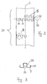
- Fig. 2 shows section II of the flexible region 31 of the inner tube 3 in Enlarged, developed view
- Fig. 3 shows a detail Fig. 2 enlarged.
- Fig. 2 shows section II of the flexible region 31 of the inner tube 3 in Enlarged, developed view
- Fig. 3 shows a detail Fig. 2 enlarged.
- Fig. 2 shows that in the wall of the Inner tube 3, a slot 5 is provided, which is helically around the longitudinal axis L of the inner tube 3 winds around (the slot is not in the Entire detail shown in Fig. 2, but only partially, however, it is present over the entire area 31).
- the slot 5 runs in a meandering manner.
- teeth through the meandering course of the slot 5 50 and indentations 51 defined.
- Indentation 51 has a tooth 50 protruding into it again.
- the width of the slot may well be in the course of the slot vary, so it does not have to be constant in every part of the slot his.
- the helix 53 of the slot 5, along which the meandering slot 5 runs, for example, a slope have in the range of about 0.5 mm / turn to about 4 mm / turn lies (similar to a thread pitch), in particular it can be about 0.9 mm be.
- the web 52 can have a width of about 0.3 mm, for example exhibit.
- the entire inner tube 3 can have a diameter of approximately 3 mm. Of course, these values are only exemplary consider and can the respective circumstances or requirements be adjusted.
- FIG. 4 shows an enlarged section V from FIG. 4.
- FIG. 4 shows an enlarged section V from FIG. 4.
- the reference symbols from FIGS. 3 and 4 have been retained, only the letter "a” has been added to them.
- FIG. 4 the course of the slot 5a along the helix 53a, which, however, has a different orientation here than in FIG. 3 (Similar to a right-hand thread, while the screw line 53 in FIG. 3 runs like a left-hand thread).
- the shape of the teeth 50a and Indentations 51a have a "square" configuration (FIGS. 3 and Fig. 4) changed to a "rounded" design.
- each thus formed tooth not in the axial direction from its associated Bulge can slide out.
- the shape of the teeth and the Indentations as well as other parameters such as the slope of the Helix, web width, slot width and their variation along the Slot etc. can be adapted to the respective requirements. These can result in particular from the type of fabric, which should be removed with the cutting tool (soft Tissue, tissue of medium hardness, very hard tissue). It is It goes without saying that the type of removal (cutting, milling, etc.) can be adjusted according to the respective fabric by an instrument with an appropriate cutting tool is selected.
Abstract
Description
Die Erfindung betrifft ein chirurgisches Instrument gemäss dem Oberbegriff des unabhängigen Patentanspruchs.The invention relates to a surgical instrument according to the preamble of the independent claim.
Instrumente der gattungsgemässen Art gibt es in unzähligen Ausführungsvarianten. Instrumente, wie sie auf dem Gebiet der Endoskopie und speziell auf dem Gebiet der Arthroskopie zum Einsatz kommen, weisen tpyischerweise ein Aussenrohr auf welches in einem distalen Bereich, häufig im Bereich des distalen Endes des Aussenrohrs, eine Öffnung aufweist, in welcher Gewebe aufgenommen werden kann. In dem Aussenrohr ist ein Innenrohr angeordnet, welches in einem distalen Bereich, häufig am distalen Ende des Innenrohrs, mit einem Schneidwerkzeug versehen ist. Das Schneidwerkzeug kann direkt an dem Innenrohr angeformt sein, es kann aber auch ein separat herstellbares Teil sein, welches mit dem Innenrohr verbunden worden ist, z.B. durch Schweissen. Mit Hilfe des Schneidwerkzeugs kann am Ort des Einsatzes Gewebe abgetrennt werden, indem das Innenrohr relativ zum Aussenrohr rotiert. Dieses abgetragene Gewebe wird dann mit Hilfe von Unterdruck zusammen mit Spülflüssigkeit, die bei dieser Art der Operation normalerweise zum Einsatz kommt, durch das Innenrohr abgesaugt. There are countless instruments of the generic type Design variants. Instruments used in the field of endoscopy and specifically used in the field of arthroscopy Typically an outer tube on which in a distal area, often has an opening in the region of the distal end of the outer tube, in which tissue can be absorbed. There is a in the outer tube Inner tube arranged, which in a distal area, often on the distal End of the inner tube is provided with a cutting tool. The Cutting tool can be molded directly onto the inner tube, it can but also be a separately producible part, which is connected to the inner tube has been connected, e.g. by welding. With the help of Cutting tool can be cut off at the place of use, by rotating the inner tube relative to the outer tube. This worn out Tissue is then vacuumed together with irrigation fluid, that is normally used in this type of surgery vacuumed the inner tube.
Mit den typischen (geradlinig verlaufenden) Instrumenten, die auf dem Gebiet der Endoskopie und insbesondere auf dem Gebiet der Arthroskopie zum Einsatz kommen, ist es jedoch für den behandelnden Arzt manchmal schwer oder sogar unmöglich, das Schneidwerkzeug an den gewünschten Ort zu bewegen (z.B. an die Unterseite der Patella, an die oberen und unteren Bereiche der Femurkondylen, oder an Bereiche der mondsichelförmig verlaufenden Menisci, insbesondere deren Vorder- und Hinterhörner), an welchem das Schneiden des Gewebes erfolgen soll. Unter "Gewebe" soll dabei jede Art von Gewebe verstanden werden, also Weichgewebe, Gewebe mittlerer Härte (wie z.B. Knorpelgewebe), aber auch sehr hartes Gewebe (wie z.B. Knochengewebe). Entsprechend sollen unter dem Begriff "Schneiden" alle in diesem Gebiet üblichen Arten von Abtragen verstanden werden, also insbesondere Schneiden, Fräsen, etc..With the typical (straight-line) instruments that are in the field endoscopy and in particular in the field of arthroscopy However, it can sometimes be difficult for the attending doctor or even impossible to get the cutting tool to the desired location move (e.g. to the underside of the patella, to the top and bottom Areas of the femoral condyles, or areas of the crescent-shaped trending Menisci, especially their front and back horns) which the tissue should be cut. Under "tissue" should any type of tissue can be understood, i.e. soft tissue, tissue medium hardness (such as cartilage tissue), but also very hard tissue (such as e.g. Bone tissue). Accordingly, under the term "cutting" all types of material removal common in this area are understood especially cutting, milling, etc.
Um das Vordringen an solche nicht oder bestenfalls nur schwer zugänglichen Orte zu erleichtern, stehen auch von der typischen geradlinigen Form abweichende Instrumente zur Verfügung, z.B. solche, bei denen das Instrument im distalen Bereich abgewinkelt ist. Mit Hilfe derartiger Instrumente ist es einfacher, an Orte zu gelangen, die mit den herkömmlichen geradlinig ausgeführten Instrumenten nur schwer oder gar nicht zugänglich sind.In order to gain access to these, or at best only with difficulty access Facilitating places are also of the typical straightforward form different instruments available, e.g. those where the Instrument is angled in the distal area. With the help of such Instruments make it easier to get to places that are more traditional straight-line instruments are difficult or impossible to access are.
Es ist unmittelbar einleuchtend, dass bei einem solchen nicht geradlinig ausgeführten Instrument der starre proximale Teil des Innenrohrs die Antriebskraft bzw. das Antriebsmoment ebenfalls auf das im distalen Bereich, vorzugsweise am distalen Ende, vorgesehene Schneidwerkzeug übertragen muss, jedoch ist dabei der nicht-geradlinige Übergangsbereich zwischen dem proximalen Bereich des Innenrohrs und dem Schneidwerkzeug zu überwinden. Mit anderen Worten, das Innenrohr muss die Antriebskraft bzw. das Antriebsmoment über einen nicht-geradlinigen Übergangsbereich hinweg auf das Schneidwerkzeug übertragen.It is immediately obvious that this is not straightforward running instrument the rigid proximal part of the inner tube the Driving force or the driving torque also to that in the distal area, preferably provided at the distal end, provided cutting tool must, however, is the non-linear transition area between the proximal area of the inner tube and the cutting tool overcome. In other words, the inner tube must have the driving force or the drive torque across a non-linear transition area transferred to the cutting tool.
Hierzu ist beispielsweise in der EP-A-0,445,918 ein Instrument beschrieben, welches zwischen dem starren proximalen Bereich und dem distalen Bereich einen flexiblen Übergangsbereich aufweist. Dieser flexible Übergangsbereich ist derart ausgeführt, dass dort mehrere diskrete Öffnungen vorgesehen sind derart, dass der Durchmesser des Innenrohres abwechselnd in der horizontalen bzw. vertikalen Richtung - jeweils senkrecht zur Längsachse des Innnerohrs - reduziert ist, sodass zwischen diesen Bereichen lediglich noch Stege vorgesehen sind, wobei benachbarte Stege jedoch miteinander verbunden sind.For this purpose, for example, an instrument is described in EP-A-0,445,918 which is between the rigid proximal area and the distal area has a flexible transition area. This flexible transition area is designed such that several discrete openings are provided there such that the diameter of the inner tube alternately in the horizontal or vertical direction - each perpendicular to the longitudinal axis of the Inner tube - is reduced, so that only between these areas Bars are provided, but adjacent bars are connected to one another are connected.
Die miteinander verbundenen Stege gewährleisten die Flexibilität des Innenrohres im Übergangsbereich, andererseit gestatten sie eine Übertragung von Kräften oder Momenten auf das distal angeordnete Schneidwerkzeug. Allerdings sind die Kräfte oder Momente, die mit einem derartig ausgebildeten flexiblen Übergangsbereich übertragen werden können, einigermassen begrenzt. Die Begrenzung der Kräfte oder Momente, die noch auf das Schneidwerkzeug übertragen werden können, ist auch Sinn und Zweck dieser Massnahme, denn die Stege dienen auch als Sollbruchstellen. Überschreiten also die auf das Schneidwerkzeug zu übertragenden Kräfte bzw. Momente einen vorgegebenen Grenzwert, so brechen die Stege. Dadurch wird verhindert, dass bei sehr grossen aufzubringenden Kräften bzw. Momenten das Schneidwerkzeug zersplittern kann und möglicherweise einzelne Bruchstücke des Schneidwerkzeugs am Ort des Eingriffs ins Gewebe gelangen können.The interconnected webs ensure the flexibility of the Inner tube in the transition area, on the other hand they allow one Transfer of forces or moments to the distal one Cutting tool. However, the forces or moments with one such a flexible transition area are transmitted can, somewhat limited. Limiting the forces or moments that can still be transferred to the cutting tool also makes sense and purpose of this measure, because the webs also serve as Predetermined breaking points. So exceed that towards the cutting tool transmitting forces or moments a predetermined limit, so break the webs. This prevents very large Forces or moments to be applied fragment the cutting tool can and possibly individual fragments of the cutting tool on Place of intervention in the tissue.
Wie bereits angesprochen, sind die zu übertragenden Kräfte bzw. Momente begrenzt. Gerade bei Wechselbelastungen, wie sie beim oszillierenden Betrieb (ständiger Wechsel der Drehrichtung des Innenrohrs relativ zum Aussenrohr) solcher Instrumente auftreten, kann es aber sehr schnell zu Brüchen der Stege kommen. Ein oszillierender Betrieb ist andererseits als Option für den Betrieb eines solchen Instruments ausserordentlich nützlich, weil man gerade bei Gewebe mittlerer Härte und bei hartem Gewebe sehr oft nicht genau vorhersagen kann, welche Drehrichtung zum Abtragen von Gewebe geeigneter ist; zum Teil hängt dies auch von der geometrischen Gestalt des abzutragenden Gewebes ab und von welcher Richtung her man an das abzutragende Gewebe gelangt. Man kann in einigen solcher Fälle mit einem oszillierenden Betrieb des Instruments ein Abtragen von Gewebe erreichen, was mit einem Betrieb in nur einer einzigen Drehrichtung nicht so einfach oder gar nicht möglich wäre. Allerdings erfordert dies, dass die Wechselbelastungen von dem proximalen Bereich des Innenrohrs auf das Schneidwerkzeug übertragen werden können.As already mentioned, the forces or moments to be transmitted are limited. Especially with alternating loads, such as with oscillating ones Operation (constant change of the direction of rotation of the inner tube relative to the Outer tube) of such instruments occur, but it can very quickly Breaks in the docks come. On the other hand, an oscillating operation is as Option extremely useful for operating such an instrument, because you are very often with medium hardness and hard tissue cannot predict exactly which direction of rotation to remove Tissue is more appropriate; in part this also depends on the geometric Shape of the tissue to be removed and from which direction reaches the tissue to be removed. You can use in some such cases an oscillating operation of the instrument a removal of tissue achieve what with an operation in only one direction of rotation not so would be easy or not possible at all. However, this requires that the Alternating loads from the proximal area of the inner tube to the Cutting tool can be transferred.
Es ist daher eine Aufgabe der Erfindung, ein Instrument vorzugschlagen, welches ein Innenrohr mit einem flexiblen Bereich aufweist, um auch für nicht-geradlinige Instrumente brauchbar zu sein, andererseits soll der flexible Bereich des Innenrohrs auch eine ausreichende Wechselfestigkeit aufweisen, um den Wechselbelastungen bei oszillierendem Betrieb standhalten zu können. Darüberhinaus soll das Innenrohr einfach in der Herstellung sein, insofern ist es auch eine Aufgabe der Erfindung, ein Rohr vorzugschlagen, welches einen flexiblen Bereich mit einer ausreichenden Wechselfestigkeit aufweist, um entsprechenden Wechselbelastungen standhalten zu können. Dabei soll das Innenrohr als solches natürlich gerade in dem flexiblen Bereich so dicht sein, dass abgesaugte Gewebeteile nicht aus dem Innenrohr austreten können.It is therefore an object of the invention to propose an instrument which has an inner tube with a flexible area to also for to be usable non-linear instruments, on the other hand the flexible Adequate fatigue strength in the area of the inner tube have to the alternating loads in oscillating operation to be able to withstand. In addition, the inner tube should simply in the Be production, so it is also an object of the invention, a tube to suggest a flexible area with a sufficient area Alternating strength exhibits corresponding alternating loads to be able to withstand. The inner tube as such should of course be straight be so tight in the flexible area that suctioned off tissue parts are not can emerge from the inner tube.
Diese Aufgabe wird durch ein Instrument gelöst, welches die Merkmale des unabhängigen Patentanspruchs aufweist. Insbesondere handelt es sich dabei um ein chirurgisches Instrument zum Entfernen von Gewebe mit einem Aussenrohr, welches in einem distalen Bereich, vorzugsweise im Bereich des distalen Endes des Aussenrohrs, eine Öffnung zum Aufnehmen von Gewebe aufweist. Ferner umfasst das Instrument ein Innenrohr, welches innerhalb des Aussenrohrs angeordnet ist und einen starren proximalen Bereich aufweist, um Kräfte bzw. Momente, die auf diesen proximalen Bereich wirken, zu einem distalen Bereich des Innenrohrs zu übertragen, vorzugsweise zum distalen Ende des Innenrohrs. Ferner umfasst das Instrument ein Schneidwerkzeug, welches an dem distalen Bereich des Innenrohrs angeordnet ist, vorzugsweise am distalen Ende des Innenrohrs, um Gewebe schneiden zu können, weiches im Bereich der Öffnung des distalen Bereichs des Aussenrohrs der Einwirkung des Schneidwerkzeugs ausgesetzt ist. Das Innenrohr weist zwischen seinem starren proximalen Bereich und dem Schneidwerkzeug einen flexiblen Bereich auf. In dem flexiblen Bereich weist das Innenrohr in seiner Wandung einen Schlitz auf der sich in Längsrichtung des Innenrohrs betrachtet schraubenlinienförmig um die Längsachse des Innenrohrs herum windet und der entlang dieser Schraubenlinine betrachtet mäanderförmig verläuft. Durch diese Ausgestaltung kann die erforderliche Wechselfestigkeit, aber eben auch die notwendige Flexibilität, erreicht werden. Die Begriffe "Schneiden" und "Schneidwerkzeug" sollen - wie bereits früher erläutert - so verstanden werden, dass sie sämtliche in diesem Gebiet üblichen Arten von Abtragen von Gewebe erfassen, also insbesondere schneiden, fräsen, etc.. bzw. entsprechende Werkzeuge, also Schneidwerkzeuge, Fräswerkzeuge, etc..This task is solved by an instrument, which the characteristics of the has independent claim. In particular, it is a surgical instrument for removing tissue with a Outer tube, which in a distal area, preferably in the area of the distal end of the outer tube, an opening for receiving tissue having. Furthermore, the instrument comprises an inner tube which is inside of the outer tube and a rigid proximal area has to forces or moments that act on this proximal area, to be transmitted to a distal region of the inner tube, preferably to distal end of the inner tube. The instrument also includes a Cutting tool, which on the distal area of the inner tube is arranged, preferably at the distal end of the inner tube, around tissue to be able to cut, soft in the area of the opening of the distal area of the outer tube is exposed to the action of the cutting tool. The Inner tube points between its rigid proximal area and the Cutting tool on a flexible area. Points in the flexible area the inner tube in its wall has a slot on it in the longitudinal direction of the inner tube viewed helically around the longitudinal axis of the Inner tube winds around and viewed along this screw line meandering. This configuration enables the required Fatigue strength, but also the necessary flexibility become. The terms "cutting" and "cutting tool" should - as already explained earlier - to be understood as being all in this area the usual types of ablation of tissue, in particular cutting, milling, etc. or appropriate tools, so Cutting tools, milling tools, etc.
Bei einem Ausführungsbeispiel des Instruments sind durch den mäanderförmig verlaufenden Schlitz abwechselnd Zähne und Einbuchtungen definiert, wobei in jeder Einbuchtung wiederum ein Zahn angeordnet ist und jeder Zahn in einer Einbuchtung angeordnet ist. Die Zähne und Einbuchtungen weisen eine Gestalt auf, die ein axiales Herausgleiten eines Zahnes aus einer Einbuchtung unmöglich macht. Dies ermöglicht, dass auch bei Instrumenten mit einem abgewinkelten distalen Bereich, bei denen der flexible Bereich zwangsläufig in axialer Richtung auseinandergezogen wird, die Zähne bei einer Drehbewegung des Innenrohrs stets in Eingriff mit der entprechenden Einbuchtung sind, sodass die Kräfte bzw. Momente sicher auf das Schneidwerkzeug übertragen werden.In one embodiment of the instrument are by the meandering slot alternating teeth and indentations defined, with a tooth in turn arranged in each indentation and each tooth is arranged in an indentation. The teeth and Indentations have a shape that axially slides out Tooth from an indentation impossible. This enables that too for instruments with an angled distal area where the flexible area is necessarily pulled apart in the axial direction, the teeth are always in engagement with the rotary movement of the inner tube corresponding indentation, so that the forces or moments are safe the cutting tool can be transferred.
Ein weitere Ausgestaltung zeichnet sich dadurch aus, dass die im Aussenrohr vorgesehene Öffnung zur Aufnahme des Gewebes im distalen Endbereich des Aussenrohrs angeordnet ist und das Schneidwerkzeug am distalen Ende des Innenrohrs angeordnet ist. Prinzipiell kann die Öffnung nämlich auch an einem anderen Ort als am distalen Ende des Aussenrohrs vorgesehen sein. Der Fall, bei welchem die Öffnung am distalen Ende des Aussenrohrs vorgesehen ist, ist jedoch der häufigste, denn man möchte ja das Instrument - wenn möglich - so wenig tief wie möglich in den Körper des Patienten bzw. in dessen Gelenk einbringen.Another embodiment is characterized in that the im Outer tube provided opening for receiving the tissue in the distal End region of the outer tube is arranged and the cutting tool on distal end of the inner tube is arranged. In principle, the opening namely also at a different location than at the distal end of the outer tube be provided. The case where the opening at the distal end of the External tube is provided, but is the most common, because you want to the instrument - if possible - as little as possible deep into the body of the Introduce the patient or into his joint.
Die Breite des Schlitzes in der Wandung des Innenrohrs kann beispielsweise im Bereich von etwa 0.05 mm bis etwa 1 mm liegen, und die Wandstärke des Innenrohrs im Bereich von etwa 0.1 mm bis etwa 0.7 mm, insbesondere im Bereich von etwa 0.15 mm bis etwa 0.5 mm.The width of the slot in the wall of the inner tube can, for example range from about 0.05 mm to about 1 mm, and the wall thickness of the Inner tube in the range of about 0.1 mm to about 0.7 mm, especially in the Range from about 0.15 mm to about 0.5 mm.
Die Steigung der Schraubenlinie, entlang welcher der in der Wandung des Innenrohrs vorgesehene Schlitz verläuft, kann beispielsweise im Bereich von etwa 0.5 mm/Windung bis etwa 4 mm/Windung liegen.The slope of the helix along which the in the wall of the The inner tube provided slot can, for example, in the range of about 0.5 mm / turn to about 4 mm / turn.
Das Schneidwerkzeug kann als separat herstellbares Element ausgebildet sein, welches mit dem distalen Ende des Innenrohrs verbunden ist. Dadurch ist es möglich, einerseits eine separate Herstellung von Schneidwerkzeug und Innenrohr zu ermöglichen, was den Herstellungsprozess erleichtert, andererseits können Schneidwerkzeug und Innenrohr zuverlässig miteinander verbunden werden, z.B. durch Schweissen, sodass die Übertragung der Kräfte bzw. Momente auf das Schneidwerkzeug gewährleistet ist. Alternativ kann das Schneidwerkzeug und das Innenrohr auch einstückig, also aus einem Stück, hergestellt sein.The cutting tool can be designed as a separately producible element be connected to the distal end of the inner tube. Thereby it is possible, on the one hand, to produce a separate cutting tool and inner tube, which facilitates the manufacturing process, on the other hand, cutting tool and inner tube can be reliable connected to each other, e.g. by welding so that Transfer of forces or moments to the cutting tool is guaranteed. Alternatively, the cutting tool and the inner tube also be made in one piece, i.e. from one piece.
Bei einem weiteren Ausführungsbeispiel kann das Aussenrohr im proximalen Bereich geradlinig verlaufen, während der distale Bereich des Aussenrohrs, in welchem das Schneidwerkzeug angeordnet ist, von dieser vom proximalen Bereich festgelegten geraden Linie abweichend ausgebildet ("abgewinkelt"). Das Innenrohr ist dann so ausgebildet, dass der flexible Bereich des Innenrohrs in einem sich zwischen dem proximalen Bereich und dem distalen Bereich des Aussenrohrs erstreckenden Übergangsbereich zu liegen kommt.In a further embodiment, the outer tube can be in the proximal Area is straight, while the distal area of the outer tube, in which the cutting tool is arranged, from the proximal Area defined straight line deviated ("angled"). The inner tube is then designed such that the flexible area of the Inner tube in a between the proximal area and the distal Area of the outer tube extending transition area comes to rest.
Dabei kann der distale Bereich des Aussenrohrs für sich alleine betrachtet ebenfalls geradlinig ausgebildet sein. Der flexible Bereich des Innenrohrs kommt in dem Übergangsbereich, in welchem der proximale Bereich und der distale Bereich ineinander einmünden, zu liegen.The distal area of the outer tube can be viewed on its own also be straight. The flexible area of the inner tube comes in the transition area in which the proximal area and the the distal area merge to lie.
Ein weitere unabhängiger Aspekt der Erfindung betrifft ein Rohr (z.B. das im Zusammenhang mit dem Instrument bereits erwähnte Innenrohr) mit einem starren proximalen Bereich und einem distal zu dem starren proximalen Bereich angeordneten flexiblen Bereich. Das Rohr weist in dem flexiblen Bereich in seiner Wandung einen Schlitz auf, der sich in Längsrichtung des Rohrs betrachtet schraubenlinienförmig um die Längsachse des Rohrs herum windet und der entlang dieser Schraubenlinine betrachtet mäanderförmig verläuft. Die Vorteile des Rohrs entsprechen den bereits anhand des Instruments gennanten Vorteilen (Wechselfestigkeit, Dichtigkeit, sichere Übertragung der erforderlichen Kräfte bzw. Momente). Another independent aspect of the invention relates to a pipe (e.g. the one in Connection with the inner tube already mentioned) with a rigid proximal area and a distal to the rigid proximal Area arranged flexible area. The tube points in the flexible Area in its wall a slot that extends in the longitudinal direction of the Pipe viewed helically around the longitudinal axis of the pipe winds and looks meandering along this screw line runs. The advantages of the pipe correspond to those already based on the Advantages called instruments (fatigue strength, tightness, safe Transfer of the required forces or moments).
Durch den mäanderförmig verlaufenden Schlitz sind abwechselnd Zähne und Einbuchtungen definiert, wobei in jeder Einbuchtung wiederum ein Zahn angeordnet ist und jeder Zahn in einer Einbuchtung angeordnet ist und die Zähne und Einbuchtungen eine Gestalt aufweisen, die ein axiales Herausgleiten eines Zahnes aus einer Einbuchtung unmöglich macht.The meandering slot alternates teeth and Indentations defined, with a tooth in each indentation is arranged and each tooth is arranged in an indentation and the Teeth and indentations have a shape that is axial Sliding a tooth out of an indentation makes it impossible.
Die Breite des Schlitzes in der Wandung des Rohrs kann im Bereich von etwa 0.05 mm bis etwa 1 mm liegen, die Wandstärke des Rohrs im Bereich von etwa 0.1 mm bis etwa 0.7 mm, insbesondere im Bereich von etwa 0.15 mm bis etwa 0.5 mm.The width of the slot in the wall of the tube can range from about 0.05 mm to about 1 mm, the wall thickness of the tube in the range from about 0.1 mm to about 0.7 mm, in particular in the range from about 0.15 mm to about 0.5 mm.
Die Steigung der Schraubenlinie, entlang welcher der in der Wandung des Innenrohrs vorgesehene Schlitz verläuft, kann im Bereich von etwa 0.5 mm/Windung bis etwa 4.0 mm/Windung liegen.The slope of the helix along which the in the wall of the The inner tube provided slot runs in the range of about 0.5 mm / turn to about 4.0 mm / turn.
Im folgenden wird die Erfindung anhand der Zeichnung näher erläutert. Es zeigen, teilweise in schematischer Darstellung und/oder im Schnitt:
- Fig. 1
- ein Ausführungsbeispiel eines erfindungsgemässen chirurgischen Instruments in zusammengebautem Zustand,
- Fig. 2
- den Ausschnitt II des flexiblen Bereichs des Innenrohrs aus Fig. 1,
- Fig. 3
- den Ausschnitt III des flexiblen Bereichs aus Fig. 2,
- Fig. 4
- einen Ausschnitt aus einem anderen Ausführungsbeispiel des
flexiblen Bereichs
und - Fig. 5
- den Ausschnitt V aus dem flexiblen Bereich der Fig. 4.
- Fig. 1
- an embodiment of a surgical instrument according to the invention in the assembled state,
- Fig. 2
- the section II of the flexible area of the inner tube from FIG. 1,
- Fig. 3
- section III of the flexible region from FIG. 2,
- Fig. 4
- a section of another embodiment of the flexible area
and - Fig. 5
- the section V from the flexible area of FIG. 4.
In Fig. 1 ist ein Ausführungsbeispiel eines erfindungsgemässen chirurgischen
Instruments 1. Man erkennt, dass das Instrument 1 ein Aussenrohr 2
aufweist, in welchem ein Innenrohr 3 drehbar angeordnet ist. Das
chirurgische Instrument 1 kann in einem Handstück (nicht dargestellt)
aufgenommen werden, in welchem ein Drehantrieb, beispielsweise ein
Elektromotor, vorgesehen sein kann zum rotatorischen Antreiben des
Innenrohrs 3. Zur Ankopplung an den Drehantrieb ist das Innenrohr 3 an
seinem proximalen Ende fest mit einem Kupplungsstück 30 verbunden,
welches mit dem Drehantrieb in Eingriff gebracht werden kann. Das
Aussenrohr 2 ist an seinem proximalen Ende fest mit einem Arretierungsstück
20 verbunden, welches von dem (nicht dargestellten) Handstück
aufgenommen und dann in diesem arretiert wird. Das Kupplungsstück 30 und
das mit diesem verbundene Innenrohr 3 sind relativ zu dem Arretierungsstück
20 und dem mit diesem verbundenen Aussenrohr 2 verdrehbar.1 shows an exemplary embodiment of a surgical device according to the
Im weiteren Verlauf vom proximalen Ende her beginnend ist das Innenrohr im
proximalen Bereich starr ausgebildet bis hin zu einem flexiblen Bereich 31.
Dieser flexible Bereich 31 des Innenrohrs 3 erstreckt sich über einen
gekrümmten Bereich 21 des Aussenrohrs 2 hinweg im wesentlichen bis hin
zu einem Schneidwerkzeug 4, welches mit dem distalen Ende des Innenrohrs
3 verbunden ist. Das Schneidwerkzeug 4 kann als separat herstellbares
Element ausgebildet sein, welches dann mittels einer geeigneten
Verbindungstechnik, beispielsweise durch Schweissen, mit dem Innenrohr 3
verbunden wird. Alternativ kann das Schneidwerkzeug 4 und das Innenrohr 3
einstückig, also aus einem Stück, hergestellt sein. Unter "schneiden" bzw.
"Schneidwerkzeug" sollen dabei - wie bereits früher mehrfach erläutert - alle
in diesem Gebiet üblichen Arten von Abtragen verstanden werden, wie z.B.
schneiden, fräsen, etc. bzw. die entsprechenden Werkzeuge, z.B.
Schneidwerkzeuge, Fräswerkzeuge, etc.. Das Schneidwerkzeug 4 kann
Gewebe abtragen, welches durch eine Öffnung 22 am distalen Ende des
Aussenrohrs 2 aufgenommen wird. Das auf diese Weise abgetragene
Gewebe kann dann durch den Innenraum des Innenrohrs 3 abgesaugt
werden. Dabei ist sichergestellt, wie noch erläutert wird, dass abgetragenes
und in das Innenrohr 3 eingesaugtes Gewebe nicht aus dem Innenraum des
Innenrohrs 3 gelangen kann. Ferner ist durch die Art und Weise, wie der
flexible Bereich 31 ausgebildet ist, sichergestellt, dass auch bei
oszillierendem Betrieb die dabei auftretenden Kräfte und Momente sicher auf
das Schneidwerkzeug 4 übertragen werden können, der flexible Bereich 31
weist also die dafür notwendige Wechselfestigkeit auf.As it continues from the proximal end, the inner tube is in the
proximal area rigidly formed up to a
Fig. 2 zeigt den Ausschnitt II des flexiblen Bereichs 31 des Innenrohrs 3 in
vergrösserter, abgewickelter Darstellung, Fig. 3 zeigt einen Ausschnitt aus
Fig. 2 vergrössert. Man erkennt (Fig. 2), dass in der Wandung des
Innenrohrs 3 ein Schlitz 5 vorgesehen ist, der sich schraubenlinienförmig um
die Längsachse L des Innenrohrs 3 herum windet (der Schlitz ist nicht im
gesamten Ausschnitt in Fig. 2 zeichnerisch dargestellt, sondern nur teilweise,
er ist aber über den gesamten Bereich 31 vorhanden). Entlang der
Schraubenlinie betrachtet verläuft dabei der Schlitz 5 mäanderförmig. Dabei
sind durch den mäanderförmigen Verlauf des Schlitzes 5 abwechselnd Zähne
50 und Einbuchtungen 51 definiert. In jede durch den Schlitz 5 gebildete
Einbuchtung 51 hinein ragt allerdings wieder ein Zahn 50 hinein. Betrachtet
man zwei übereinander angeordnete Schlitze, so befindet sich zwischen den
beiden Schlitzen ein Steg 52. Von diesem Steg stehen in axialer Richtung
betrachtet die Zähne abwechselnd nach oben bzw. nach unten ab und ragen
in entsprechende Einbuchtungen 51 hinein. Dabei weisen die einzelnen
Zähne 50 und Einbuchtungen 51 eine Gestalt auf, die ein axiales
Herausgleiten eines Zahnes 50 aus einer Einbuchtung 51 unmöglich macht. 2 shows section II of the
Es ist nämlich klar, dass bei dem gekrümmten ("abgewinkelten") Instrument
nach Fig. 1 der flexible Bereich 31 des Innerohrs 3 einer Beanspruchung auf
Zug ausgesetzt ist. Der Schlitz 5 muss also so ausgebildet sein, dass die
durch ihn gebildeten Zähne 50 und Einbuchtungen einerseits den
gekrümmten Bereich 21 des Aussenrohrs 2 überwinden, andererseits eine
Übertragung der erforderlichen Kräfte bzw. Momente auf das
Schneidwerkzeug 4 ermöglichen, insbesondere also auch die erforderliche
Wechselfestigkeit für oszillierenden Betrieb aufweisen.It is clear that the curved ("angled")
Bei einem typischen Anwendungsbeispiel kann die Wandstärke der
Wandung des Innenrohrs 3 im Bereich von etwa 0.1 mm bis etwa 0.7 mm
liegen, insbesondere im Bereich von etwa 0.15 mm bis etwa 0.5 mm; die
Breite des Schlitzes 5 kann im Bereich von etwa 0.05 mm bis etwa 1 mm
liegen. Die Breite des Schlitzes kann dabei im Verlauf des Schlitzes durchaus
variieren, sie muss also nicht in jedem Teilbereich des Schlitzes konstant
sein. Die Schraubenlinie 53 des Schlitzes 5, entlang welcher der
mäanderförmige Schlitz 5 verläuft, kann beispielsweise eine Steigung
aufweisen, die im Bereich von etwa 0.5 mm/Windung bis etwa 4 mm/Windung
liegt (ählich einer Gewindesteigung), insbesondere kann sie etwa 0.9 mm
betragen. Der Steg 52 kann hier beispielsweise eine Breite von etwa 0.3 mm
aufweisen. Das gesamte Innenrohr 3 kann einen Durchmesser von etwa 3
mm aufweisen. Selbstverständlich sind diese Werte nur als beispielhaft zu
betrachten und können den jeweiligen Gegebenheiten bzw. Anforderungen
angepasst werden.In a typical application example, the wall thickness of the
Wall of the inner tube 3 in the range from about 0.1 mm to about 0.7 mm
lie, in particular in the range from about 0.15 mm to about 0.5 mm; the
The width of the
Mit einem auf diese Weise ausgebildeten Innenrohr 3 können Gewebeteile,
die mit Hilfe des Schneidwerkzeugs 4 abgetragen worden sind, zusammen
mit einer Spülflüssigkeit durch den Innenraum des Innenrohrs 3 abgesaugt
werden, ohne dass durch den Schlitz 5 hindurch Gewebeteile zwischen das
Innenrohr 3 und das Aussenrohr 2 gelangen können, die ein Festfressen des
Innenrohrs 3 im Aussenrohr 2 begünstigen könnten.With an inner tube 3 formed in this way, fabric parts,
which have been removed with the aid of the
Ein anderes Ausführungsbeispiel des flexiblen Bereichs ist in Fig. 4 gezeigt,
wieder in abgewickelter Darstellung, Fig. 5 zeigt vergrössert den Ausschnitt V
aus Fig. 4. Die Bezugszeichen aus Fig. 3 und Fig. 4 sind beibehalten worden,
es wurde ihnen lediglich der Buchstabe "a" hinzugefügt. Man erkennt
demzufolge in Fig. 4 den Verlauf des Schlitzes 5a entlang der Schraubenlinie
53a, die hier allerdings eine andere Orientierung aufweist als in Fig. 3
(ähnlich einem Rechtsgewinde, während die Schraubenlinie 53 in Fig. 3
ähnlich einem Linksgewinde verläuft). Auch die Form der Zähne 50a und der
Einbuchtungen 51a hat sich von einer "eckigen" Ausgestaltung (Fig. 3 und
Fig. 4) zu einer "abgerundeten" Ausgestaltung verändert. Gleich geblieben ist
jedoch, dass ein Herausgleiten eines Zahnes 50a aus einer Einbuchtung 51a
nicht möglich ist. Dies ist besonders gut aus Fig. 5 ersichtlich, in welcher der
Zahn 50a in der Einbuchtung 51a angeordnet ist, einmal ohne
Zugbeanspruchung (durchgezogene Linie) und einmal mit
Zugbeanspruchung (gestrichelte Linie). Im Falle der Zugbeanspruchung
(gestrichelte Linie), dies ist bei Instrumenten mit einem zwischen dem
proximalen und dem distalen Bereich liegenden gekrümmten
Übergangsbereich des Aussenrohrs der Normalfall, liegt der Zahn 50a
seitlich fest an der Einbuchtung 51a an, während er im Falle ohne
Zugbeanspruchung (durchgezogene Linie) ein geringes Spiel (nämlich die
Schlitzbreite an der jeweiligen Stelle) aufweist. Man erkennt in Fig. 5 auch
gut, dass die Schlitzbreite entlang des Schlitzes 5a variieren kann. So ist der
Schlitz im seitlichen Bereich deutlich breiter als am Kopfende.Another embodiment of the flexible area is shown in Fig. 4,
again in a developed representation, FIG. 5 shows an enlarged section V
from FIG. 4. The reference symbols from FIGS. 3 and 4 have been retained,
only the letter "a" has been added to them. One recognises
consequently in FIG. 4 the course of the slot 5a along the
Es ist klar, dass noch viele weitere Möglichkeiten des Verlaufs des mäanderförmigen Schlitzes möglich sind. Wesentlich ist, dass der jeweils dadurch gebildete Zahn nicht in axialer Richtung aus seiner zugehörigen Ausbuchtung herausgleiten kann. Die Gestalt der Zähne und der Einbuchtungen wie auch sonstige Parameter wie Steigung der Schraubenlinie, Stegbreite, Schlitzbreite und deren Variierung entlang des Schlitzes etc., können an die jeweiligen Anforderungen angepasst werden. Diese können sich insbesondere durch die Art des Gewebes ergeben, welches mit dem Schneidwerkzeug abgetragen werden soll (weiches Gewebe, gewebe mittlerer Härte, sehr hartes Gewebe). Es ist selbstverständlich, dass auch die Art des Abtragens (Schneiden, Fräsen, etc.) entsprechend dem jeweiligen Gewebe angepasst werden kann, indem ein Instrument mit einem entsprechenden Schneidwerkzeug gewählt wird.It is clear that there are many more options for the course of the meandering slot are possible. It is essential that each thus formed tooth not in the axial direction from its associated Bulge can slide out. The shape of the teeth and the Indentations as well as other parameters such as the slope of the Helix, web width, slot width and their variation along the Slot etc. can be adapted to the respective requirements. These can result in particular from the type of fabric, which should be removed with the cutting tool (soft Tissue, tissue of medium hardness, very hard tissue). It is It goes without saying that the type of removal (cutting, milling, etc.) can be adjusted according to the respective fabric by an instrument with an appropriate cutting tool is selected.
Claims (13)
wobei das Innenrohr (3) zwischen seinem starren proximalen Bereich und dem Schneidwerkzeug (4) einen flexiblen Bereich (31) aufweist,
dadurch gekennzeichnet,
the inner tube (3) having a flexible region (31) between its rigid proximal region and the cutting tool (4),
characterized by
Priority Applications (3)
| Application Number | Priority Date | Filing Date | Title |
|---|---|---|---|
| DE59802909T DE59802909D1 (en) | 1998-09-17 | 1998-09-17 | Flexible shaft surgical instrument |
| EP98810930A EP0986989B1 (en) | 1998-09-17 | 1998-09-17 | Surgical instrument comprising flexible shaft |
| US10/267,114 US7105003B2 (en) | 1998-09-17 | 2002-10-09 | Surgical instrument |
Applications Claiming Priority (1)
| Application Number | Priority Date | Filing Date | Title |
|---|---|---|---|
| EP98810930A EP0986989B1 (en) | 1998-09-17 | 1998-09-17 | Surgical instrument comprising flexible shaft |
Publications (2)
| Publication Number | Publication Date |
|---|---|
| EP0986989A1 true EP0986989A1 (en) | 2000-03-22 |
| EP0986989B1 EP0986989B1 (en) | 2002-01-23 |
Family
ID=8236329
Family Applications (1)
| Application Number | Title | Priority Date | Filing Date |
|---|---|---|---|
| EP98810930A Revoked EP0986989B1 (en) | 1998-09-17 | 1998-09-17 | Surgical instrument comprising flexible shaft |
Country Status (2)
| Country | Link |
|---|---|
| EP (1) | EP0986989B1 (en) |
| DE (1) | DE59802909D1 (en) |
Cited By (10)
| Publication number | Priority date | Publication date | Assignee | Title |
|---|---|---|---|---|
| WO2003022162A1 (en) * | 2001-09-13 | 2003-03-20 | Medtronic Xomed, Inc. | Flexible inner tubular member and rotary tissue cutting instrument having flexible inner tubular member |
| EP1462063A1 (en) * | 2003-03-25 | 2004-09-29 | Ethicon Endo-Surgery, Inc. | Flexible housing element for a surgical tool |
| EP1664565A4 (en) * | 2004-06-25 | 2006-09-13 | Monaspump Co Ltd | Flexible transmission shaft |
| EP1834600A1 (en) | 2006-03-15 | 2007-09-19 | Karl Storz GmbH & Co. KG | Device for cleaning a flexible quill shaft for a medical instrument |
| DE102006013979A1 (en) * | 2006-03-15 | 2007-09-20 | Karl Storz Gmbh & Co. Kg | Flexible hollow shaft for a medical instrument |
| EP2080918A1 (en) | 2008-01-15 | 2009-07-22 | IMA Integrated Microsystems Austria GmbH | Flexible drive shaft |
| EP2351594A3 (en) * | 2010-01-29 | 2012-03-28 | Cordis Corporation | Highly flexible tubular device with high initial torque response for medical use |
| US8353898B2 (en) | 2009-05-29 | 2013-01-15 | Aesculap Ag | Surgical instrument |
| US8382742B2 (en) | 2009-05-29 | 2013-02-26 | Aesculap Ag | Surgical instrument |
| US9468359B2 (en) | 2011-04-12 | 2016-10-18 | Aesculap Ag | Control apparatus |
Families Citing this family (3)
| Publication number | Priority date | Publication date | Assignee | Title |
|---|---|---|---|---|
| DE102009024244A1 (en) | 2009-05-29 | 2010-12-02 | Aesculap Ag | Surgical instrument i.e. shaver, has drive element including flexible section that has ring segments, which are connected with each other in axial and radial directions in form-fit manner using protrusions and recesses |
| EP2255734A1 (en) | 2009-05-29 | 2010-12-01 | Aesculap Ag | Surgical instrument |
| DE202009007979U1 (en) | 2009-05-29 | 2009-08-06 | Aesculap Ag | Surgical instrument |
Citations (7)
| Publication number | Priority date | Publication date | Assignee | Title |
|---|---|---|---|---|
| CH119033A (en) * | 1926-02-28 | 1927-04-01 | Fritz Pletscher | Flexible shaft. |
| US4646738A (en) * | 1985-12-05 | 1987-03-03 | Concept, Inc. | Rotary surgical tool |
| DE4002449A1 (en) * | 1989-02-07 | 1990-08-09 | Volkswagen Ag | Elastically flexible but torsionally rigid drive shaft - is formed from helical coils with intermeshing teeth |
| EP0445918A1 (en) | 1990-02-07 | 1991-09-11 | SMITH & NEPHEW DYONICS INC | Surgical cutting instrument |
| US5488761A (en) * | 1994-07-28 | 1996-02-06 | Leone; Ronald P. | Flexible shaft and method for manufacturing same |
| US5512007A (en) * | 1993-09-30 | 1996-04-30 | Astro Machine Works, Inc. | System and process for manufacturing a flexible connection in a hollow metal device |
| US5669926A (en) * | 1993-01-25 | 1997-09-23 | Aust & Taylor Medical Corporation | Surgical instrument |
-
1998
- 1998-09-17 EP EP98810930A patent/EP0986989B1/en not_active Revoked
- 1998-09-17 DE DE59802909T patent/DE59802909D1/en not_active Revoked
Patent Citations (7)
| Publication number | Priority date | Publication date | Assignee | Title |
|---|---|---|---|---|
| CH119033A (en) * | 1926-02-28 | 1927-04-01 | Fritz Pletscher | Flexible shaft. |
| US4646738A (en) * | 1985-12-05 | 1987-03-03 | Concept, Inc. | Rotary surgical tool |
| DE4002449A1 (en) * | 1989-02-07 | 1990-08-09 | Volkswagen Ag | Elastically flexible but torsionally rigid drive shaft - is formed from helical coils with intermeshing teeth |
| EP0445918A1 (en) | 1990-02-07 | 1991-09-11 | SMITH & NEPHEW DYONICS INC | Surgical cutting instrument |
| US5669926A (en) * | 1993-01-25 | 1997-09-23 | Aust & Taylor Medical Corporation | Surgical instrument |
| US5512007A (en) * | 1993-09-30 | 1996-04-30 | Astro Machine Works, Inc. | System and process for manufacturing a flexible connection in a hollow metal device |
| US5488761A (en) * | 1994-07-28 | 1996-02-06 | Leone; Ronald P. | Flexible shaft and method for manufacturing same |
Cited By (14)
| Publication number | Priority date | Publication date | Assignee | Title |
|---|---|---|---|---|
| WO2003022162A1 (en) * | 2001-09-13 | 2003-03-20 | Medtronic Xomed, Inc. | Flexible inner tubular member and rotary tissue cutting instrument having flexible inner tubular member |
| EP1462063A1 (en) * | 2003-03-25 | 2004-09-29 | Ethicon Endo-Surgery, Inc. | Flexible housing element for a surgical tool |
| EP1664565A4 (en) * | 2004-06-25 | 2006-09-13 | Monaspump Co Ltd | Flexible transmission shaft |
| EP1834600A1 (en) | 2006-03-15 | 2007-09-19 | Karl Storz GmbH & Co. KG | Device for cleaning a flexible quill shaft for a medical instrument |
| DE102006013979A1 (en) * | 2006-03-15 | 2007-09-20 | Karl Storz Gmbh & Co. Kg | Flexible hollow shaft for a medical instrument |
| US8721806B2 (en) | 2006-03-15 | 2014-05-13 | Karl Storz Gmbh & Co. Kg | Device for cleaning a flexible hollow shaft of a medical instrument |
| US8672921B2 (en) | 2006-03-15 | 2014-03-18 | Karl Storz Gmbh & Co. Kg | Flexible hollow shaft for a medical instrument |
| EP2080918A1 (en) | 2008-01-15 | 2009-07-22 | IMA Integrated Microsystems Austria GmbH | Flexible drive shaft |
| US8382742B2 (en) | 2009-05-29 | 2013-02-26 | Aesculap Ag | Surgical instrument |
| US8353898B2 (en) | 2009-05-29 | 2013-01-15 | Aesculap Ag | Surgical instrument |
| RU2515515C2 (en) * | 2009-05-29 | 2014-05-10 | Эскулап Аг | Surgical instrument |
| US8357140B2 (en) | 2010-01-29 | 2013-01-22 | Cordis Corporation | Highly flexible tubular device with high initial torque response for medical use |
| EP2351594A3 (en) * | 2010-01-29 | 2012-03-28 | Cordis Corporation | Highly flexible tubular device with high initial torque response for medical use |
| US9468359B2 (en) | 2011-04-12 | 2016-10-18 | Aesculap Ag | Control apparatus |
Also Published As
| Publication number | Publication date |
|---|---|
| EP0986989B1 (en) | 2002-01-23 |
| DE59802909D1 (en) | 2002-03-14 |
Similar Documents
| Publication | Publication Date | Title |
|---|---|---|
| EP0275375B1 (en) | Rasp-like extracting instrument | |
| EP2434965B1 (en) | Surgical instrument | |
| DE4305376C1 (en) | Medical instrument shaft | |
| EP0764423B2 (en) | Bendable pipe | |
| EP0986989B1 (en) | Surgical instrument comprising flexible shaft | |
| DE69731786T2 (en) | Endoscopic scraper blade with resilient cutting edges | |
| EP0928164B1 (en) | Bone cutter | |
| EP2305145B1 (en) | Dismountable medical pincer system | |
| EP2696741B1 (en) | Control apparatus | |
| EP2434966A1 (en) | Surgical instrument | |
| DE102008034927B4 (en) | Device for removing tissue and knives for such a device | |
| EP0648477A2 (en) | Drill head for the medullary canal | |
| EP0308957A1 (en) | Recanalisation catheter | |
| EP2314234B1 (en) | Surgical instrument | |
| EP3451943B1 (en) | Saw blade | |
| EP2892442B1 (en) | Surgical, torque-transmitting instrument including associated tool | |
| EP1637065B1 (en) | Endoscopic instrument | |
| EP3518814B1 (en) | Dental treatment instrument for operating a rotating tool | |
| WO2008145380A1 (en) | Surgical instrument and method for production thereof | |
| EP2298209B1 (en) | Medical resector with rotating high frequency electrode and drive unit for same | |
| WO2001076491A1 (en) | Device for treating human and/or animal tissue | |
| EP1360928B1 (en) | Laryngoscope that can be spread | |
| DE19719051A1 (en) | Medullary boring head preferably for placement on flexible drive shafts | |
| DE19619970A1 (en) | Endoscopic instrument | |
| DE8306675U1 (en) | Locking nail |
Legal Events
| Date | Code | Title | Description |
|---|---|---|---|
| PUAI | Public reference made under article 153(3) epc to a published international application that has entered the european phase |
Free format text: ORIGINAL CODE: 0009012 |
|
| AK | Designated contracting states |
Kind code of ref document: A1 Designated state(s): DE FR GB IT |
|
| AX | Request for extension of the european patent |
Free format text: AL;LT;LV;MK;RO;SI |
|
| 17P | Request for examination filed |
Effective date: 20000918 |
|
| AKX | Designation fees paid |
Free format text: AT BE CH CY LI |
|
| RBV | Designated contracting states (corrected) |
Designated state(s): DE FR GB IT |
|
| RAP1 | Party data changed (applicant data changed or rights of an application transferred) |
Owner name: KARL STORZ GMBH & CO. KG |
|
| RIN1 | Information on inventor provided before grant (corrected) |
Inventor name: HILTEBRANDT, SIEGFRIED |
|
| 17Q | First examination report despatched |
Effective date: 20001222 |
|
| GRAG | Despatch of communication of intention to grant |
Free format text: ORIGINAL CODE: EPIDOS AGRA |
|
| RTI1 | Title (correction) |
Free format text: SURGICAL INSTRUMENT COMPRISING FLEXIBLE SHAFT |
|
| GRAG | Despatch of communication of intention to grant |
Free format text: ORIGINAL CODE: EPIDOS AGRA |
|
| GRAH | Despatch of communication of intention to grant a patent |
Free format text: ORIGINAL CODE: EPIDOS IGRA |
|
| RTI1 | Title (correction) |
Free format text: SURGICAL INSTRUMENT COMPRISING FLEXIBLE SHAFT |
|
| GRAH | Despatch of communication of intention to grant a patent |
Free format text: ORIGINAL CODE: EPIDOS IGRA |
|
| GRAA | (expected) grant |
Free format text: ORIGINAL CODE: 0009210 |
|
| REG | Reference to a national code |
Ref country code: GB Ref legal event code: IF02 |
|
| AK | Designated contracting states |
Kind code of ref document: B1 Designated state(s): DE FR GB IT |
|
| REF | Corresponds to: |
Ref document number: 59802909 Country of ref document: DE Date of ref document: 20020314 |
|
| GBT | Gb: translation of ep patent filed (gb section 77(6)(a)/1977) |
Effective date: 20020407 |
|
| ET | Fr: translation filed | ||
| PLBQ | Unpublished change to opponent data |
Free format text: ORIGINAL CODE: EPIDOS OPPO |
|
| PLBI | Opposition filed |
Free format text: ORIGINAL CODE: 0009260 |
|
| 26 | Opposition filed |
Opponent name: RICHARD WOLF GMBH Effective date: 20021022 |
|
| PLBF | Reply of patent proprietor to notice(s) of opposition |
Free format text: ORIGINAL CODE: EPIDOS OBSO |
|
| PLBF | Reply of patent proprietor to notice(s) of opposition |
Free format text: ORIGINAL CODE: EPIDOS OBSO |
|
| PLBB | Reply of patent proprietor to notice(s) of opposition received |
Free format text: ORIGINAL CODE: EPIDOSNOBS3 |
|
| RDAF | Communication despatched that patent is revoked |
Free format text: ORIGINAL CODE: EPIDOSNREV1 |
|
| PGFP | Annual fee paid to national office [announced via postgrant information from national office to epo] |
Ref country code: FR Payment date: 20050819 Year of fee payment: 8 |
|
| PGFP | Annual fee paid to national office [announced via postgrant information from national office to epo] |
Ref country code: GB Payment date: 20050822 Year of fee payment: 8 |
|
| PGFP | Annual fee paid to national office [announced via postgrant information from national office to epo] |
Ref country code: DE Payment date: 20051005 Year of fee payment: 8 |
|
| RDAG | Patent revoked |
Free format text: ORIGINAL CODE: 0009271 |
|
| STAA | Information on the status of an ep patent application or granted ep patent |
Free format text: STATUS: PATENT REVOKED |
|
| 27W | Patent revoked |
Effective date: 20050628 |
|
| GBPR | Gb: patent revoked under art. 102 of the ep convention designating the uk as contracting state |
Free format text: 20050628 |
|
| PGFP | Annual fee paid to national office [announced via postgrant information from national office to epo] |
Ref country code: IT Payment date: 20060930 Year of fee payment: 9 |