EP0905797A2 - Semiconductor light source and method of fabrication - Google Patents
Semiconductor light source and method of fabrication Download PDFInfo
- Publication number
- EP0905797A2 EP0905797A2 EP98116218A EP98116218A EP0905797A2 EP 0905797 A2 EP0905797 A2 EP 0905797A2 EP 98116218 A EP98116218 A EP 98116218A EP 98116218 A EP98116218 A EP 98116218A EP 0905797 A2 EP0905797 A2 EP 0905797A2
- Authority
- EP
- European Patent Office
- Prior art keywords
- layer stack
- light source
- carrier body
- source according
- contact
- Prior art date
- Legal status (The legal status is an assumption and is not a legal conclusion. Google has not performed a legal analysis and makes no representation as to the accuracy of the status listed.)
- Granted
Links
Images

Classifications
-
- H—ELECTRICITY
- H01—ELECTRIC ELEMENTS
- H01L—SEMICONDUCTOR DEVICES NOT COVERED BY CLASS H10
- H01L33/00—Semiconductor devices with at least one potential-jump barrier or surface barrier specially adapted for light emission; Processes or apparatus specially adapted for the manufacture or treatment thereof or of parts thereof; Details thereof
- H01L33/48—Semiconductor devices with at least one potential-jump barrier or surface barrier specially adapted for light emission; Processes or apparatus specially adapted for the manufacture or treatment thereof or of parts thereof; Details thereof characterised by the semiconductor body packages
- H01L33/62—Arrangements for conducting electric current to or from the semiconductor body, e.g. lead-frames, wire-bonds or solder balls
-
- H—ELECTRICITY
- H01—ELECTRIC ELEMENTS
- H01L—SEMICONDUCTOR DEVICES NOT COVERED BY CLASS H10
- H01L33/00—Semiconductor devices with at least one potential-jump barrier or surface barrier specially adapted for light emission; Processes or apparatus specially adapted for the manufacture or treatment thereof or of parts thereof; Details thereof
- H01L33/005—Processes
- H01L33/0093—Wafer bonding; Removal of the growth substrate
-
- H—ELECTRICITY
- H01—ELECTRIC ELEMENTS
- H01L—SEMICONDUCTOR DEVICES NOT COVERED BY CLASS H10
- H01L33/00—Semiconductor devices with at least one potential-jump barrier or surface barrier specially adapted for light emission; Processes or apparatus specially adapted for the manufacture or treatment thereof or of parts thereof; Details thereof
- H01L33/02—Semiconductor devices with at least one potential-jump barrier or surface barrier specially adapted for light emission; Processes or apparatus specially adapted for the manufacture or treatment thereof or of parts thereof; Details thereof characterised by the semiconductor bodies
- H01L33/20—Semiconductor devices with at least one potential-jump barrier or surface barrier specially adapted for light emission; Processes or apparatus specially adapted for the manufacture or treatment thereof or of parts thereof; Details thereof characterised by the semiconductor bodies with a particular shape, e.g. curved or truncated substrate
-
- H—ELECTRICITY
- H01—ELECTRIC ELEMENTS
- H01L—SEMICONDUCTOR DEVICES NOT COVERED BY CLASS H10
- H01L33/00—Semiconductor devices with at least one potential-jump barrier or surface barrier specially adapted for light emission; Processes or apparatus specially adapted for the manufacture or treatment thereof or of parts thereof; Details thereof
- H01L33/36—Semiconductor devices with at least one potential-jump barrier or surface barrier specially adapted for light emission; Processes or apparatus specially adapted for the manufacture or treatment thereof or of parts thereof; Details thereof characterised by the electrodes
- H01L33/38—Semiconductor devices with at least one potential-jump barrier or surface barrier specially adapted for light emission; Processes or apparatus specially adapted for the manufacture or treatment thereof or of parts thereof; Details thereof characterised by the electrodes with a particular shape
- H01L33/382—Semiconductor devices with at least one potential-jump barrier or surface barrier specially adapted for light emission; Processes or apparatus specially adapted for the manufacture or treatment thereof or of parts thereof; Details thereof characterised by the electrodes with a particular shape the electrode extending partially in or entirely through the semiconductor body
-
- H—ELECTRICITY
- H01—ELECTRIC ELEMENTS
- H01L—SEMICONDUCTOR DEVICES NOT COVERED BY CLASS H10
- H01L2924/00—Indexing scheme for arrangements or methods for connecting or disconnecting semiconductor or solid-state bodies as covered by H01L24/00
- H01L2924/0001—Technical content checked by a classifier
- H01L2924/0002—Not covered by any one of groups H01L24/00, H01L24/00 and H01L2224/00
-
- H—ELECTRICITY
- H01—ELECTRIC ELEMENTS
- H01L—SEMICONDUCTOR DEVICES NOT COVERED BY CLASS H10
- H01L33/00—Semiconductor devices with at least one potential-jump barrier or surface barrier specially adapted for light emission; Processes or apparatus specially adapted for the manufacture or treatment thereof or of parts thereof; Details thereof
- H01L33/02—Semiconductor devices with at least one potential-jump barrier or surface barrier specially adapted for light emission; Processes or apparatus specially adapted for the manufacture or treatment thereof or of parts thereof; Details thereof characterised by the semiconductor bodies
- H01L33/10—Semiconductor devices with at least one potential-jump barrier or surface barrier specially adapted for light emission; Processes or apparatus specially adapted for the manufacture or treatment thereof or of parts thereof; Details thereof characterised by the semiconductor bodies with a light reflecting structure, e.g. semiconductor Bragg reflector
-
- H—ELECTRICITY
- H01—ELECTRIC ELEMENTS
- H01L—SEMICONDUCTOR DEVICES NOT COVERED BY CLASS H10
- H01L33/00—Semiconductor devices with at least one potential-jump barrier or surface barrier specially adapted for light emission; Processes or apparatus specially adapted for the manufacture or treatment thereof or of parts thereof; Details thereof
- H01L33/36—Semiconductor devices with at least one potential-jump barrier or surface barrier specially adapted for light emission; Processes or apparatus specially adapted for the manufacture or treatment thereof or of parts thereof; Details thereof characterised by the electrodes
- H01L33/40—Materials therefor
- H01L33/405—Reflective materials
Definitions
- the invention relates to a semiconductor light source with a epitaxially grown layer stack according to the generic term of claim 1 and a process for their preparation.
- Examples of light sources of the type mentioned are transparent Infrared diodes (IREDs) and light emitting diodes (LEDs).
- the Layers of the layer stack of such light sources are on a growth substrate in the form of a crystal epitaxially grown together. Part of those generated in the layer stack Photons will emerge from the stack towards the growth substrate emitted and absorbed there.
- the support body When retrofitting the transparent support body on the stack of layers, the support body becomes flat and such intimately with the surface facing away from the growth substrate connected to the stack of layers that the support body similar is directly firmly connected to the layer stack, like the growth substrate itself.
- This immediate attachment is, for example, by melting or growing the transparent support body made to the layer stack.
- the growth substrate is removed from the Layer stack removed, after which layer stack and more transparent Support body together as a similarly uniform composite body as before, layer stack and growth substrate are present and the transparent support body the layer stack now supports the growth substrate as originally. In In this state, the layer stack is contacted electrically.
- the invention specified in claim 1 is based on the object a semiconductor light source with low photon absorption to provide the structurally simpler than is also easier to manufacture.
- the semiconductor light source according to the invention is advantageous neither a photon absorbing growth substrate another support body for supporting the layer stack present, the intimately with the stack of layers to one uniform composite body connected and for in the layer stack generated photons is transparent and the structure and complicates the manufacture of the light source.
- the light source according to the invention essentially only exists still from the layer stack of a small total thickness of at most 50 ⁇ m alone, that for electrical contacting and mechanical stability on a separate carrier body arranged and separate with little effort Lanyard is connected to this body.
- a the manufacturing complicating intimate flat connection between the surface of this thin layer stack and a transparent support body is advantageously not more needed.
- a surface of the layer stack facing the carrier body be a refractive surface attached to an optical medium with a relative to a refractive index of the layer stack significantly lower refractive index, for example air, and due to the relatively large jump in the refractive index in the layer stack generated photons partially reflected, but then not get from the layer stack into the carrier body, but contribute to the optical performance of the light source.
- this has the advantage that everyone is in the layer stack generated photons that hit the reflector device, not get into the separate carrier body, but in Direction from the carrier body are reflected and to the optical Contribute performance of the light source according to the invention can, on the other hand, that the separate carrier body also Light sources of high optical power from any Material can consist, in particular of one in the layer stack generated photon absorbing material.
- Suitable means that on the facing the carrier body Surface of the layer stack can be formed like for example, a reflective applied to this surface Layer or a formed in this surface reflective optical grating, for example a Bragg mirror.
- the reflector device has a light source one on the surface facing the carrier body Layer stack arranged reflective contact (Claim 3).
- This contact can be used for electrical connection of the layer stack are used on the carrier body, and since it is reflective, there are no additional ones reflective agents necessary. This simplifies it the production of the light source according to the invention.
- the layer stack of the light source according to the invention can advantageously only from those for the function of the semiconductor light source only necessary epitaxially grown Layers exist.
- a typical total thickness of those grown on growth substrates and only from those necessary for the function of the light source epitaxially grown layers existing alone Layer stacking of known diode light sources such as LEDs and IREDS in particular high optical performance is in the range between 3 ⁇ m and 15 ⁇ m.
- the only one Layer stack such a small total thickness in the area have from only 3 ⁇ m to 15 ⁇ m (claim 4).
- the invention is advantageously for implementation suitable for IREDs and LEDs with high optical performance and accordingly in this case the layer stack is the light source according to the invention of the layer stack of an IRED (Claim 5) or an LED (Claim 6), wherein it is in this Case is also advantageous, a reflector device after Claim 2 to use.
- the invention is not restricted to such diode light sources, but also on other semiconductor light sources,
- semiconductor lasers can be used, under certain circumstances the problem of leakage generated in the layer stack Photons through the surface facing the carrier body can be insignificant, so that preventive measures waived such an exit from the outset can be.
- the separate lanyard to attach to each other layer stack and separate carrier body is preferably from a firm connection between the Layer stack and adhesive producing this carrier body (Claim 7), preferably an adhesive (Claim 8) and / or a solder (claim 9).
- Solder and / or electrically conductive adhesive are preferred used where an electrically conductive connection not disturbing or even necessary, electrically insulating Adhesive where there is an electrically conductive connection is to avoid.
- connection means for example a clamp connection, can be used.
- An electrical connection of semiconductor material of the layer stack the light source according to the invention to a contact of the carrier body is preferably one of these semiconductor material directly contacting semiconductor contact connected to this contact of the carrier body (claim 12).
- the semiconductor contact is preferably an ohmic contact, can also be a Schottky contact under certain circumstances.
- a contact of the carrier body with a Semiconductor contact is preferably solder and / or more conductive Glue used.
- the layers are made of semiconductor material different conductivity types, between which the optically active transition from one to the other another conductivity type is usually formed parallel to a plane of the layers one above the other arranged so that they are perpendicular to this plane different sides of the transition. Accordingly must in such a diode light source semiconductor material Conductivity type on one side and semiconductor material of the different from this one conductivity type Conductivity type contacted on the other side of the transition and the electrically separated contacts of the carrier body can be connected.
- the layer stack is preferably so flat on arranged the carrier body that the surface of the layer stack, in which the recess is formed, the carrier body is turned (claim 14).
- connection of the semiconductor materials different from each other Conductivity type of the layer stack to each other separate contacts of the carrier body can be in this Case advantageously produced in a particularly short way when the contacts are electrically separated of the carrier body on one facing the layer stack
- Surface of the support body are arranged, preferably as follows:
- the semiconductor contact is on a contact of the carrier body and the other contact of the layer stack to one electrical separated from this one contact of the carrier body connected other contact of the support body, for example by touching it directly.
- a semiconductor contact is arranged in the depression Semiconductor material of the layer stack, which is based on the Support body facing away from the optically active transition of the stack is contacted directly.
- This semiconductor contact in the recess is electrical from the semiconductor material of the one conductivity type on the carrier body facing side of the optically active transition, from the semiconductor contact contacting this material and from the contact of the carrier body connected to this connection contact separated, but electrically with the other contact of the layer stack connected.
- the one connected to the semiconductor contact in the recess other contact of the layer stack and an electrical connection these two contacts can advantageously be made consist of the same material as this semiconductor contact, wherein the connection is applied to a side wall of the recess can be.
- the layer stack two facing away from each other and at an angle to the plane of the Layers standing end faces which is the surface the layer stack in which the depression is formed, limit on opposite sides, and that the recess in this surface from an end face extends to the other (claim 15).
- Transitional semiconductor material of the layer stack preferably has a high electrical conductivity perpendicular to the plane of the layers of the layer stack on (claim 16).
- the optical emitted by the light source according to the invention Power is generated in the layer stack and passes through the Surface of the layer stack. About this optical performance if possible, all should be created in the layer stack Photons contribute. On the one hand it is necessary that as much as possible little of these photons are absorbed in the stack, i.e. the stack should be as transparent as possible for these photons on the other hand, as many of these photons as possible, preferably all, through the surface of the layer stack quit ..
- the greatest possible transparency of the layer stack is achieved, if the layers of the layer stack, except if at all in an area of an optically active transition, for im Layer stacks generated photons are transparent 17).
- Photons from the layer stack are expedient a facility to facilitate the exit of im Layer stacks generated photons from the layer stack provided (claim 18).
- any means is suitable that the exit of the photons through the surface of the layer stack.
- an agent can be applied to the surface Antireflection coating, which is the refractive index jump the optically refractive surface with a higher refractive index Inside the stack to lower refractive index outside of the Stacks and thus facilitates the exit of the photons.
- One way to easily implement a facility for The easing of the exit of photons is to avoid them of plane-parallel reflecting surface sections of the layer stack, i.e. turned away from each other Surface sections should not be flat and / or parallel to each other be. Such surface sections can be used alone through geometrical design of the layer stack and thus can be realized with little effort.
- Surface sections arranged at an angle to one another can, for example, two turned away from each other and end faces at an angle to the plane of the layers, which are at an angle to each other in this plane run and / or at least one end face of which is inclined is arranged at an angle to the plane.
- One formed on the surface of the layer stack finely structured relief can be achieved by roughening the surface or by an uneven microstructuring of the surface be generated. Such a relief is preferred on the surface of the layer stack facing away from the carrier body trained, but can also on the carrier body facing surface and on all other surface sections be provided.
- Surface sections of the layer stack including one, several or all end faces of the stack and / or at least a wall surface of a recess are preferably at angles less than 30 ° for non-potted and less than 40 ° for encapsulated light sources according to the invention inclined to the plane, the direction of the inclination is arbitrary.
- the layers can be arranged at an angle to the plane Surface areas of the stack of layers shaped as desired be. Also the shape of the base or the outline of the layer stack in a vertical projection onto one Layer of layers parallel plane is generally arbitrary selectable.
- the layer stack according to the invention can advantageously have III-V semiconductor material in a conventional manner (Claim 21), including all common III-V compounds from In, GA, Al, As, P, N to GaAs, InP, GaP or GaN base.
- An optically active transition can be a pn or pin transition be.
- the layer stack according to the invention can advantageously be designed in a conventional manner so that the optically active transition one between two layers Semiconductor material of different conductivity types to each other of the layer stack arranged active layer has, in which photons can be generated (claim 22). To all other layers of semiconductor material are on the active layer of the layer stack as transparent as possible.
- the carrier body advantageously consists of a material which has a similar coefficient of thermal expansion as the layer stack comprises (claim 23), i.e. the thermal Expansion coefficient of the materials of the carrier body and the stack of layers give way at temperatures, that during operation of the semiconductor light source according to the invention occur or to which the source is exposed, at most so little apart that no harmful temperature-related Deformations of the layer stack occur which impair its optical quality and an optical and / or mechanical long-term stability of the invention Can affect light source.
- the carrier body preferably consists of a good heat conductor Material (claim 24) that has good heat dissipation guaranteed away from the stack of layers.
- the contacts are advantageous on a surface of the carrier body facing the layer stack arranged, with a particularly short and easy connection of the semiconductor materials various Conductivity type of the layer stack on both sides which then results in an optically active transition to these contacts, if these materials face the carrier body Surface of the stack are contacted because of then the contacts on the surface of the carrier body and semiconductor contacts contacting these semiconductor materials on the surface of the layer stack facing this surface directly opposite and able to touch.
- the electrical connection the light source according to the invention from the outside electrically separated contacts on the carrier body is designed so that on the one hand the electrically insulated Contact of the carrier body and the other be from the surface of the carrier body itself formed contact indirectly through the electrically conductive support body from the outside is contacted, preferably so that one of the layer stack contacted surface of the support body is (claim 26).
- the light source according to the invention is preferred and advantageous manufactured so that on a growth substrate epitaxially the one intended for the light source Layer stack grown, the associated with the growth substrate Layers of layers on the carrier body, which the electrically having separate contacts arranged and attached to the connecting means and electrically contacted is, and then the so attached to the support body Layer sequence is separated from the growth substrate (Claim 27).
- This process is related to the separation of the layer stack preferably carried out by the growth substrate in such a way that an intermediate layer epitaxially on the growth substrate is grown from a material that is selective with a acting etchant is etchable, which the Materialiden of the layers of the layer stack not or less strongly attacks than the material of the intermediate layer that on the intermediate layer epitaxially the layers of the layer stack be grown, and that to separate the layer stack from the growth substrate the intermediate layer with the selective acting etchant is etched. (Claim 28).
- the process can be performed using a growth substrate GaAs, a layer stack based on InGaAlAs, one Intermediate layer made of AlAs and an etchant containing hydrofluoric acid be carried out from.
- the manufacture of the semiconductor light sources according to the invention is advantageously carried out so that several Layer stack in the wafer network as islands or mesets in the Grid of several carrier bodies are prepared, the
- the shape of the base of each layer stack can be selected as desired is, preferably with sides arranged at an acute angle to one another.
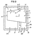
- the layer stack is 1 and the carrier body designated with 2.
- the layers of the layer stack 1 are parallel to a defined plane 100 of the layers arranged.
- the layer stack 1 has two facing away from each other Surfaces 14 and 14 'between which the total thickness d of the stack 1 is measured.
- the layer stack 1 can have any structure of epitaxially on one another have grown layers, a semiconductor light source may have.
- the semiconductor light source in particular a diode light source in which the layer stack 1 of epitaxially grown ones Layers of semiconductor material different from one another Conductivity type exists between which at least an optically active transition from is designed for another conductivity type, wherein Conductivity type semiconductor material and semiconductor material of the other conductivity type of the layer stack 1 are electrically contacted separately from each other.
- a typical total thickness d of a layer stack 1 is more conventional Diode light sources are in the range between 3 ⁇ m and 15 ⁇ m. Even with a diode light source according to the invention has the only arranged on the separate support body 2 Layer stack 1 advantageously a total thickness d im Range from 3 ⁇ m to 15 ⁇ m.
- the optically active transition usually at least one active layer of the layer stack 1 assigned, in which photons generated this transition become.
- a layer stack 1 This consists of a layer 11 made of semiconductor material of a conductivity type, a layer 13 of semiconductor material of the other conductivity type and an active one Layer 12 for the generation of photons between the Layer 11 and layer 13 is arranged.
- level 100 of the layers arranged parallel to one another 11, 12 and 13 is a central layer level of the active Taken layer 12.
- the layer stack 1 is shown in FIGS. 1, 3 and 4 in such a way that the plane 100 of the layers is horizontal and vertical to the drawing plane and in Figure 2 parallel to the drawing plane is arranged.
- the photon-producing optically active transition is at 10 is located between the layer 11 and the Layer 13 and extends parallel to level 100 of the Layers. Active layer 12 is to be counted at transition 10.
- the number of epitaxially grown layers of the layer stack 1 is not limited to three and can be larger.
- layers 11, 12 and 13 can each be laminated be.
- the semiconductor material of layers 11 and 13 of the layer stack 1 chosen so that it is in between these Layers 11 and 12 arranged active layer 12 generated Photons is transparent.
- carrier bodies 2 and Layer stack 1 arranged relative to one another so that a surface 24 of carrier body 2 facing stack 1 and the plane 100 of the layers of the stack 1 essentially are parallel to each other.
- Surfaces 14 and 14 'of the carrier body 2 is the Surface 14 opposite the surface 24 of the carrier body 2.
- the electrically separate contacts 21 and 22 of the Carrier body 2 are in the example of Figures 1, 2 and 4 layers of metal between the opposite and substantially parallel surfaces 14 and 24 of the layer stack 1 and carrier body 2 are arranged and are fastened on the surface 24 of the carrier body 2.
- the contacts 21 and 22 of the Surface 24 must be isolated. In any case, they must be firm be connected to the surface 24, for example by means of Adhesive or by vapor deposition.
- the layer stack 1 is arranged, for example, in such a way that the layer 11 between the support body 2 and the optical active transition 10, which is the surface 24 of the carrier body 2 opposite surface 14 of the Layer stack 1 made of the semiconductor material of this layer 11 exists.
- a Semiconductor contact 15 which is the semiconductor material of the layer 11 of the stack 1 contacted directly, and another Contact 160, which is electrically from the semiconductor contact 15 and the Semiconductor material of the layer 11 is arranged separately.
- the semiconductor contact 15 is preferably an ohmic contact, but depending on the structure of the layer stack 1 could also for example a Schottky contact.
- the semiconductor contact 15 lies directly on the contact 21 and the other contact 160 directly on the contact 22 of the Carrier body 2. It could also be the other way around.
- a semiconductor contact 16 is arranged in the recess 17, which is the semiconductor material of the other conductivity type Layer 13 contacted directly, for example on a Bottom surface 170 of the recess 17, and preferably one ohmic contact. This semiconductor contact 16 is electrical connected to the other contact 160, for example through an electrical connection line 161.
- the semiconductor contact 16, the electrical connection line 161 and the other contact 160 must be electrically from the semiconductor material layer 11, the material contacting this Semiconductor connection contact 15 and the contact 21 of the Carrier body 2 be separated.
- the other contact 160 and the electrical connection line 161 can advantageously be made of the same material as the semiconductor contact 16 exist.
- the electrical connection line 161 can on one of the side wall surfaces 171 of the recess 17 may be applied.
- the electrical isolation of the other contact 160 and the Connection line 161 from the semiconductor material of layer 11 of the stack 1 can by an electrically insulating adhesive layer 162 between layer 11 and the other contact 160 and the connecting line 161 can be implemented, which also the fixed connection of the other contact 160 with the layer stack.
- layer 11 consists of p-doped semiconductor material, i.e. Conductivity type material p, and the layer 13 made of n-doped semiconductor material, i.e. material of conductivity type n. It could also be reversed, i.e. the layer 11 of n-doped and the Layer 13 consist of p-doped semiconductor material.
- the semiconductor material of the layer 13 on the side of the transition 10 facing away from the carrier body 2 the layer stack 1 has a higher electrical conductivity perpendicular to the plane 100 of the layers than the semiconductor material the layer 11 between the transition 10 and the carrier body 2.
- the separate connection means 3 for attaching the thin Layer stack 1 on the carrier body 2 is, for example essentially made of an electrically conductive adhesive and / or a solder that connects to layer 11 Semiconductor contact 15 of the layer stack 1 with the associated contact 21 of the carrier body 2 and also other contact 160 firmly connected to layer 11 of the stack 1 firmly with the associated contact 22 of the carrier body 2 connects.
- Prerequisite for this preferred Method of establishing a fixed connection between the stack of layers 1 and support body 2 is via contacts, the given solid connection of the semiconductor contact 15 and other contact 160 with the layer stack 1 and the contacts 21 and 22 with the carrier body 2.
- the attachment of the layer stack 1 to the carrier body 2 does not have to be made via contacts.
- the attachment of the layer stack 1 to the carrier body 2 does not have to be made via contacts.
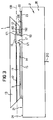
- the layer stack 1 has two sides facing away from one another perpendicular or at an angle to the plane 100 of the Layers of standing end faces 19 which cover the surface 14 of the layer stack 1, in which the recess 17 is formed is, on opposite sides, and the recess 17 extends in this surface 14 from one of these two end faces 19 across the whole Layer stack 1 to the other end face 19.
- the depression 17 forms an elongated trench, which is parallel to level 100 of the layers in extends in a longitudinal direction r1 between the end faces 19, which is perpendicular to the plane of the drawing in FIGS. 1, 3 and 4.
- These figures show and perpendicular to the surface 24 side surface 26 of the carrier body parallel to the plane of the drawing 2 and the end face 19 of the layer stack 1, which in the figure 2 are each arranged below
- 2 and 4 is the Recess 17 preferably over a gap 17 'between the separate contacts 21 and 22 of the carrier body 2 arranged so that these contacts 21 and 22 and accordingly the contacts 15 and 160 of the layer stack 1 opposite sides of the recess 17 are located.
- this gap 17 also in this direction r1.
- Surface 4 striking photons back into the layer stack 4 consists, for example, of the semiconductor contact 15 which is on the surface 14 of the layer stack facing the carrier body 2 1 is designed and has a reflective effect, i.e. its flat side 150 facing the layer stack 1 is a reflective surface.
- This contact 15 should the Carrier body 2 facing surface 14 of the layer stack 1 cover as large a area as possible, so as much photons as possible reflected and lost as little as possible.
- a device 6 to facilitate exit from the Layer stack 1 generated photons from the layer stack 1 points obliquely at an angle relative to each other
- Surface sections that, for example, from obliquely in an angle ⁇ to the plane of the layers 100 arranged end faces 18, 18 of the layer stack 1, perpendicular to the plane 100 of the layers arranged side wall surfaces 171, 171 of the depression 17 and in the plane 100 of the layers obliquely at an angle ⁇ to each other and obliquely or end faces arranged perpendicular to the plane 100 of the layers 19, 19 of the layer stack 1 exist and each assigned in pairs to each other, two at an angle form surface sections arranged relative to one another.
- the end faces 18, 18, 19, 19 and wall surfaces 171, 171 can be used in any other Way obliquely at an angle relative to each other be arranged.
- two of each other turned surface sections - end surfaces and / or wall surfaces - stand at an angle to each other. The latter is guaranteed if two of them are turned away from each other Surface sections of at least one obliquely at an angle and the other at a different angle Angle arranged obliquely or perpendicular to the plane 100 of the layers and / or these two surface sections in the plane 100 of the layers obliquely at an angle to one another run.
- the device 6 has to facilitate the exit of photons on the surface of the layer stack 1 formed finely structured relief 61.
- the entire one To understand the surface facing the carrier body 2 Surface 14, facing away from the carrier body 2 Surface 14 'and all other surface sections 18, 19, 170, 171.
- the relief 61 can be on any of these Surface sections 18, 19, 170, 171 may be formed, However, as indicated in a fragmentary manner in FIG. 2, at least on the surface 14 'facing away from the carrier body 2 be provided.
- the angle ⁇ , at which an end surface 18, 19 obliquely to Level 100 of the layers is preferably less than 30 ° for non-potted and less than 40 ° for encapsulated light sources according to the invention, the direction the inclination is arbitrary. Also a wall surface 171 of the Recess 17 can ⁇ at an angle at such an angle Level 100 of the layers can be arranged inclined.
- the layer stack 1 made of III-V semiconductor material and the carrier body 2 consists of silicon, both have one sufficiently similar coefficients of thermal expansion and the carrier body 2 is sufficiently good heat conductor.
- the carrier body 2 can be made of electrically insulating material, for example, undoped or semi-insulating semiconductor material like silicon, or from electrically conductive material, for example conductive semiconductor material such as silicon or metal.
- FIG. 1 A modified exemplary embodiment is shown in FIG a carrier body 2 made of electrically conductive material, this differs from the example according to FIGS. 1, 2 and 4 distinguishes that one of the contacts 21 and 22 of the Carrier body 2, for example the contact 22, from the carrier body 2 electrically isolated and the electrically from this Contact 22 separated other contact 21 by the material of the Carrier body 2 is formed itself.
- 3 shows parts, with parts of the embodiment according to the figures 1 and 2 match, designated by the same reference numerals.
- the contact 22 is the carrier body 2 by an electrically insulating layer 23, for example a layer of adhesive from the surface 24 of the Carrier body 2 insulated and by an electrically conductive Connection means 3, for example solder or electrically conductive Adhesive, with the other contact 160 of the layer stack 1 connected.
- the contact 21 of the carrier body 2 is formed by the surface 24 itself and by a electrically conductive connection means 3, for example solder or electrically conductive adhesive, directly with the semiconductor contact 15 of the layer stack 1 connected.
- each of the electrically separated contacts 21 and 22 of the carrier body 2 on the one facing the layer stack 1 Surface 24 with one external connection contact each 210 or 220, for example a bonding wire, is provided in the example according to FIG. 3, that of the carrier body 2 is electrical isolated contact 22 on the surface 24 with a outer contact 220 and one of this surface 24th and thus surface 25 of the layer facing away from the layer stack 1 Carrier body 2 is provided with an external connection contact 210, so that in this case the semiconductor light source from the Back of the carrier body 2 and through this is contacted outside.
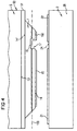
- the surface 14 facing the carrier body 2 of the layer stack 1 which is turned away from the growth substrate 5 free surface of the layer stack 1 before separation of the layer stack 1 structured by the growth substrate 5 and contacted, e.g. with the recess 17 and the contacts 15, 16 and 160 including the connecting line 161 becomes.
- FIG. 4 shows a carrier body 2 according to FIGS. 1 and 2 assumed that a carrier body 2 according to FIG 3 can be used.
- a material grown with a selective acting Etchant is etchable, which is the material of every epitaxial to grow layer of layer stack 1, in the example each of layers 11, 12 and 13, none or less strongly attacks than the material of the intermediate layer 51 that on the intermediate layer 51 the layers of the Layer stack 1 are grown and that to separate the Layer stack 1 from the growth substrate 5, the intermediate layer 51 is etched with the selectively acting etchant.
- a growth substrate 5 made of GaAs Layer stack 1 based on InGaAlAs, an intermediate layer 51 made of AlAs and a hydrofluoric acid etchant.
Abstract
Description
Die Erfindung betrifft eine Halbleiterlichtquelle mit einem epitaktisch gewachsenen Schichtenstapel nach dem Oberbegriff des Anspruchs 1 und ein Verfahren zu ihrer Herstellung.The invention relates to a semiconductor light source with a epitaxially grown layer stack according to the generic term of claim 1 and a process for their preparation.
Beispiele für Lichtquellen der genannten Art sind transparente Infrarotdioden (IREDs) und Leuchtdioden (LEDs). Die Schichten des Schichtenstapels solcher Lichtquellen sind auf einem Wachstumssubstrat in Form eines Kristalls epitaktisch aufeinander gewachsen. Ein Teil der im Schichtenstapel erzeugten Photonen wird aus dem Stapel in Richtung zum Wachstumssubstrat emittiert und dort absorbiert.Examples of light sources of the type mentioned are transparent Infrared diodes (IREDs) and light emitting diodes (LEDs). The Layers of the layer stack of such light sources are on a growth substrate in the form of a crystal epitaxially grown together. Part of those generated in the layer stack Photons will emerge from the stack towards the growth substrate emitted and absorbed there.
Für derartige Halbleiterlichtquellen möglichst hoher optischer Leistung wird versucht, die Absorption im Wachstumssubstrat weitgehend zu vermeiden. Mittel hierzu sind - außer der in wenigen Fällen möglichen Verwendung von für die Photonen transparenten Wachstumssubstraten - eingefügte Bragg-Reflektoren aus Halbleitermaterial zwischen dem Wachstumssubstrat und dem gewachsenen Schichtenstapel oder das nachträgliche Anbringen eines für die Photonen transparenten Stützkörpers an den Schichtenstapel, beispielsweise durch Waferbonden.For such semiconductor light sources the highest possible optical Performance is trying to absorb the growth substrate largely avoided. Means for this are - except the possible use of for the photons in a few cases transparent growth substrates - inserted Bragg reflectors of semiconductor material between the growth substrate and the grown layer stack or the subsequent one Attach a transparent for the photons Support body on the layer stack, for example by wafer bonding.
Beim nachträglichen Anbringen des transparenten Stützkörpers an den Schichtenstapel wird der Stützkörper flächig und derart innig mit der vom Wachstumssubstrat abgekehrten Oberfläche des Schichtenstapels verbunden, daß der Stützkörper ähnlich unmittelbar fest mit dem Schichtenstapel verbunden ist, wie das Wachstumssubstrat selbst. Dieses unmittelbare Anbringen wird beispiesweise durch Anschmelzen oder Anwachsen des transparenten Stützkörpers an den Schichtenstapel vorgenommen. Nach dem Anbringen wird das Wachstumssubstrat vom Schichtenstapel entfernt, wonach Schichtenstapel und transparenter Stützkörper gemeinsam als ähnlich einheitlicher Verbundkörper wie vorher Schichtenstapel und Wachstumssubstrat vorliegen und der transparente Stützkörper den Schichtenstapel jetzt wie ursprünglich das Wachstumssubstrats stützt. In diesem Zustand wird der Schichtenstapel elektrisch kontaktiert.When retrofitting the transparent support body on the stack of layers, the support body becomes flat and such intimately with the surface facing away from the growth substrate connected to the stack of layers that the support body similar is directly firmly connected to the layer stack, like the growth substrate itself. This immediate attachment is, for example, by melting or growing the transparent support body made to the layer stack. After attachment, the growth substrate is removed from the Layer stack removed, after which layer stack and more transparent Support body together as a similarly uniform composite body as before, layer stack and growth substrate are present and the transparent support body the layer stack now supports the growth substrate as originally. In In this state, the layer stack is contacted electrically.
Der im Anspruch 1 angegebenen Erfindung liegt die Aufgabe zugrunde, eine Halbleiterlichtquelle mit geringer Photonenabsorption bereitzustellen, die sowohl baulich einfacher als auch einfacher herzustellen ist.The invention specified in claim 1 is based on the object a semiconductor light source with low photon absorption to provide the structurally simpler than is also easier to manufacture.
Bei der erfindungsgemäßen Halbleiterlichtquelle ist vorteilhafterweise weder ein Photonen absorbierendes Wachstumssubstrat noch ein Stützkörper zum Stützen des Schichtenstapels vorhanden, der innig mit dem Schichtenstapel zu einem einheitlichen Verbundkörper verbunden und für im Schichtenstapel erzeugte Photonen transparent ist und der den Aufbau und die Herstellung der Lichtquelle verkompliziert.In the semiconductor light source according to the invention is advantageous neither a photon absorbing growth substrate another support body for supporting the layer stack present, the intimately with the stack of layers to one uniform composite body connected and for in the layer stack generated photons is transparent and the structure and complicates the manufacture of the light source.
Die erfindungsgemäße Lichtquelle besteht im wesentlichen nur noch aus dem Schichtenstapel einer geringen Gesamtdicke von höchstens 50 µm allein, der zur elektrischen Kontaktierung und mechanischen Stabilität an einem gesonderten Trägerkörper angeordnet und durch ein wenig Aufwand erforderndes gesondertes Verbindungsmittel mit diesem Körper verbunden ist. Eine die Herstellung verkomplizierende innige flächige Verbindung zwischen der Oberfläche dieses dünnen Schichtenstapels und einem transparenten Stützkörper ist vorteilhafterweise nicht mehr erforderlich.The light source according to the invention essentially only exists still from the layer stack of a small total thickness of at most 50 µm alone, that for electrical contacting and mechanical stability on a separate carrier body arranged and separate with little effort Lanyard is connected to this body. A the manufacturing complicating intimate flat connection between the surface of this thin layer stack and a transparent support body is advantageously not more needed.
Aufgrund der Bauweise der erfindungsgemäßen Lichtquelle kann eine dem Trägerkörper zugekehrte Oberfläche des Schichtenstapels eine brechende Fläche sein, die an ein optisches Medium mit einer relativ zu einer Brechzahl des Schichtenstapels deutlich kleineren Brechzahl, beispielsweise Luft, grenzt und aufgrund des relativ großen Brechzahlsprungs im Schichtenstapel erzeugte Photonen teilweise reflektiert, die dann nicht aus dem Schichtenstapel in den Trägerkörper gelangen, sondern zur optischen Leistung der Lichtquelle beitragen.Due to the design of the light source according to the invention a surface of the layer stack facing the carrier body be a refractive surface attached to an optical medium with a relative to a refractive index of the layer stack significantly lower refractive index, for example air, and due to the relatively large jump in the refractive index in the layer stack generated photons partially reflected, but then not get from the layer stack into the carrier body, but contribute to the optical performance of the light source.
Besonders vorteilhaft ist es, wenn an der dem Trägerkörper zugekehrten Oberfläche des Schichtenstapels eine Reflektoreinrichtung zum Reflektieren der im Schichtenstapel erzeugten und auf diese Fläche treffenden Photonen zurück in den Schichtenstapel ausgebildet ist (Anspruch 2).It is particularly advantageous if on the carrier body facing surface of the layer stack a reflector device to reflect those generated in the layer stack and photons striking this surface back in the layer stack is formed (claim 2).
Dies hat den Vorteil zum einen, daß alle im Schichtenstapel erzeugten Photonen, die auf die Reflektoreinrichtung treffen, nicht in den gesonderten Trägerkörper gelangen, sondern in Richtung vom Trägerkörper fort reflektiert werden und zur optischen Leistung der erfindungsgemäßen Lichtquelle beitragen können, zum andern, daß der gesonderte Trägerkörper auch bei Lichtquellen hoher optischer Leistung aus einem beliebigen Material bestehen kann, insbesondere aus einem die im Schichtenstapel erzeugten Photonen absorbierenden Material.On the one hand, this has the advantage that everyone is in the layer stack generated photons that hit the reflector device, not get into the separate carrier body, but in Direction from the carrier body are reflected and to the optical Contribute performance of the light source according to the invention can, on the other hand, that the separate carrier body also Light sources of high optical power from any Material can consist, in particular of one in the layer stack generated photon absorbing material.
Als Reflektoreinrichtung sind alle reflektierend wirkenden Mittel geeignet, die an der dem Trägerkörper zugekehrten Oberfläche des Schichtenstapels ausgebildet werden können wie beispielsweise eine auf dieser Oberfläche aufgebrachte reflektierende Schicht oder ein in dieser Oberfläche ausgebildetes reflektierendes optisches Gitter, beispielsweise ein Braggspiegel.As a reflector device, all are reflective Suitable means that on the facing the carrier body Surface of the layer stack can be formed like for example, a reflective applied to this surface Layer or a formed in this surface reflective optical grating, for example a Bragg mirror.
Bei einer bevorzugten und vorteilhaften Ausgestaltung der erfindungsgemäßen Lichtquelle weist die Reflektoreinrichtung einen auf der dem Trägerkörper zugekehrten Oberfläche des Schichtenstapels angeordneten reflektierenden Kontakt auf (Anspruch 3). Dieser Kontakt kann zum elektrischen Anschließen des Schichtenstapels an den Trägerkörper verwendet werden, und da er reflektierend wirkt, sind keine zusätzlichen reflektierend wirkenden Mittel notwendig. Dies vereinfacht die Herstellung der erfindungsgemäßen Lichtquelle.In a preferred and advantageous embodiment of the invention The reflector device has a light source one on the surface facing the carrier body Layer stack arranged reflective contact (Claim 3). This contact can be used for electrical connection of the layer stack are used on the carrier body, and since it is reflective, there are no additional ones reflective agents necessary. This simplifies it the production of the light source according to the invention.
Der Schichtenstapel der erfindungsgemäßen Lichtquelle kann vorteilhafterweise nur aus den für die Funktion der Halbleiterlichtquelle allein notwendigen epitaktisch gewachsenen Schichten bestehen.The layer stack of the light source according to the invention can advantageously only from those for the function of the semiconductor light source only necessary epitaxially grown Layers exist.
Eine typische Gesamtdicke von auf Wachstumssubstraten gewachsenen und nur aus den für die Funktion der Lichtquelle notwendigen epitaktisch gewachsenen Schichten allein bestehenden Schichtenstapeln bekannter Diodenlichtquellen wie LEDs und IREDS insbesonderer hoher optischer Leistung liegt im Bereich zwischen 3 µm und 15 µm. Mit der Erfindung können vorteilhafterweise solche Diodenlichtquellen mit derart dünnen Schichtenstapeln realisiert werden und entsprechend kann bei der erfindungsgemäßen Lichtquelle vorteilhafterweise der alleinige Schichtenstapel eine solche geringe Gesamtdicke im Bereich von nur 3 µm bis 15 µm aufweisen (Anspruch 4).A typical total thickness of those grown on growth substrates and only from those necessary for the function of the light source epitaxially grown layers existing alone Layer stacking of known diode light sources such as LEDs and IREDS in particular high optical performance is in the range between 3 µm and 15 µm. With the invention can advantageously such diode light sources with such thin layer stacks can be realized and accordingly at light source according to the invention advantageously the only one Layer stack such a small total thickness in the area have from only 3 µm to 15 µm (claim 4).
Insbesondere ist die Erfindung vorteilhafterweise zur Realisierung
von IREDs und LEDs hoher optischer Leistung geeignet
und entsprechend ist in diesem Fall der Schichtenstapel der
erfindungsgemäßen Lichtquelle der Schichtenstapel einer IRED
(Anspruch 5) oder einer LED (Anspruch 6), wobei es in diesem
Fall überdies vorteilhaft ist, eine Reflektoreinrichtung nach
Anspruch 2 zu verwenden.In particular, the invention is advantageously for implementation
suitable for IREDs and LEDs with high optical performance
and accordingly in this case the layer stack is the
light source according to the invention of the layer stack of an IRED
(Claim 5) or an LED (Claim 6), wherein it is in this
Case is also advantageous, a reflector device after
Die Erfindung ist aber nicht auf solche Diodenlichquellen beschränkt, sondern auch auf andere Halbleiterlichtquellen, beispielsweise Halbleiterlaser anwendbar, wobei unter Umständen das Problem eines Austritts von im Schichtenstapel erzeugten Photonen durch die dem Trägerkörper zugekehrte Oberfläche unbedeutend sein kann, so daß auf Maßnahmen zur Verhinderung eines solchen Austritts von vorneherein verzichtet werden kann. However, the invention is not restricted to such diode light sources, but also on other semiconductor light sources, For example, semiconductor lasers can be used, under certain circumstances the problem of leakage generated in the layer stack Photons through the surface facing the carrier body can be insignificant, so that preventive measures waived such an exit from the outset can be.
Das gesonderte Verbindungsmittel zum aneinander befestigen von Schichtenstapel und gesondertem Trägerkörper besteht vorzugsweise aus einem eine feste Verbindung zwischen dem Schichtenstapel und diesem Trägerkörper herstellenden Haftmittel (Anspruch 7), vorzugsweise ein Klebstoff (Anspruch 8) und/oder ein Lot (Anspruch 9).The separate lanyard to attach to each other layer stack and separate carrier body is preferably from a firm connection between the Layer stack and adhesive producing this carrier body (Claim 7), preferably an adhesive (Claim 8) and / or a solder (claim 9).
Lot und/oder elektrisch leitender Klebstoff werden vorzugsweise dort verwendet, wo eine elektrisch leitende Verbindung nicht stört oder gar notwendig ist, elektrisch isolierender Klebstoff dort, wo eine elektrisch leitende Verbindung zu vermeiden ist.Solder and / or electrically conductive adhesive are preferred used where an electrically conductive connection not disturbing or even necessary, electrically insulating Adhesive where there is an electrically conductive connection is to avoid.
Auch andere Verbindungsmittel, beispielsweise eine Klemmverbindung, können verwendet werden.Other connection means, for example a clamp connection, can be used.
Eine erfindungsgemäße Diodenlichtquelle, insbesondere eine Quelle hoher optischer Leistung, kann vorteilhafterweise derart baulich einfach ausgebildet sein, daß der Schichtenstapel
- Schichten aus Halbleitermaterial voneinander verschiedenen Leitfähigkeitstyps aufweist, zwischen denen ein optisch aktiver Übergang von einem zu einem anderen Leitfähigkeitstyp zur Erzeugung der Photonen ausgebildet ist, und
- Halbleitermaterial eines Leitfähigkeitstyps des Schichtenstapels und Halbleitermaterial des anderen Leitfähigkeitstyps elektrisch voneinander getrennt am Trägerkörper kontaktiert sind (Anspruch 10).
- Has layers of semiconductor material of different conductivity types from one another, between which an optically active transition from one conductivity type to another is formed to generate the photons, and
- Semiconductor material of one conductivity type of the layer stack and semiconductor material of the other conductivity type are contacted separately from one another on the carrier body (claim 10).
In diesem Fall ist es zweckmäßig wenn der Trägerkörper
- einen elektrischen Kontakt, an den Halbleitermaterial eines Leitfähigkeitstyps des Schichtenstapels angeschlossen ist, und
- einen von dem einen Kontakt getrennten anderen elektrischen Kontakt aufweist, an den Halbleitermaterial des anderen Leitfähigkeitstyps des Schichtenstapels angeschlossen ist (Anspruch 11).
- an electrical contact to which semiconductor material of a conductivity type of the layer stack is connected, and
- has another electrical contact separated from the one contact, to which semiconductor material of the other conductivity type of the layer stack is connected (claim 11).
Ein elektrischer Anschluß von Halbleitermaterial des Schichtenstapels der erfindungsgemäßen Lichtquelle an einen Kontakt des Trägerkörpers ist vorzugsweise durch einen dieses Halbleitermaterial unmittelbar kontaktierenden Halbleiterkontakt an diesen Kontakt des Trägerkörpers angeschlossen (Anspruch 12).An electrical connection of semiconductor material of the layer stack the light source according to the invention to a contact of the carrier body is preferably one of these semiconductor material directly contacting semiconductor contact connected to this contact of the carrier body (claim 12).
Der Halbleiterkontakt ist vorzugsweise ein ohmscher Kontakt, kann unter Umständen aber auch ein Schottky-Kontakt sein.The semiconductor contact is preferably an ohmic contact, can also be a Schottky contact under certain circumstances.
Zum Verbinden eines Kontaktes des Trägerkörpers mit einem Halbleiterkontakt wird vorzugsweise Lot und/oder leitender Klebstoff verwendet.For connecting a contact of the carrier body with a Semiconductor contact is preferably solder and / or more conductive Glue used.
Bei Diodenlichtquellen sind die Schichten aus Halbleitermaterial voneinander verschiedenen Leitfähigkeitstyps, zwischen denen der optisch aktive Übergang vom einen zum davon verschiedenen anderen Leitfähigkeitstyp ausgebildet ist, üblicherweise parallel zu einer Ebene der Schichten übereinander angeordnet, so daß sie sich senkrecht zu dieser Ebene auf verschiedenen Seiten des Übergangs befinden. Entsprechend muß bei einer solchen Diodenlichtquelle Halbleitermaterial eines Leitfähigkeitstyps auf einer Seite und Halbleitermaterial des von diesem einen Leitfähigkeitstyp verschiedenen anderen Leitfähigkeitstyps auf der anderen Seite des Übergangs kontaktiert und an die elektrisch voneinander getrennten Kontakte des Trägerkörpers angeschlossen werden.In the case of diode light sources, the layers are made of semiconductor material different conductivity types, between which the optically active transition from one to the other another conductivity type is usually formed parallel to a plane of the layers one above the other arranged so that they are perpendicular to this plane different sides of the transition. Accordingly must in such a diode light source semiconductor material Conductivity type on one side and semiconductor material of the different from this one conductivity type Conductivity type contacted on the other side of the transition and the electrically separated contacts of the carrier body can be connected.
Halbleitermaterial eines Leitfähigkeitstyps und Halbleitermaterial des davon verschiedenen anderen Leitfähigkeitstyps des Schichtenstapels der erfindungsgemäßen Lichtquelle können in einem solchen Fall jedoch vorteilhafterweise auf der gleichen Seite des Übergangs, aber elektrisch voneinander getrennt an die elektrisch voneinander getrennten Kontakte des Trägerkörpers angeschlossen sein, wenn
- der Schichtenstapel in einer zu einer Ebene der Schichten im wesentlichen parallelen Oberfläche eine Vertiefung aufweist, die sich von dieser Oberfläche aus in Richtung senkrecht zur Ebene der Schichten durch einen Übergang von Halbleitermaterial eines Leitfähigkeitstyps zu Halbleitermaterial eines vom einen Leitfähigkeitstyp verschiedenen anderen Leitfähigkeitstyps des Schichtenstapels hindurch erstreckt, und wenn
- das Halbleitermaterial des einen Leitfähigkeitstyps an einen Kontakt des Trägerkörpers und das Halbleitermaterial des anderen Leitfähigkeitstyps in der Vertiefung an einen elektrisch von diesem einen Kontakt des Trägerkörpers getrennten anderen Kontakt des Trägerkörpers angeschlossen ist (Anspruch 13).
- the layer stack has a depression in a surface substantially parallel to a plane of the layers, which extends from this surface in the direction perpendicular to the plane of the layers through a transition from semiconductor material of one conductivity type to semiconductor material of a different conductivity type of the layer stack that differs from one conductivity type , and if
- the semiconductor material of one conductivity type is connected to a contact of the carrier body and the semiconductor material of the other conductivity type in the recess is connected to another contact of the carrier body which is electrically separated from this one contact of the carrier body (claim 13).
Der Schichtenstapel ist dabei vorzugsweise derart flach auf dem Trägerkörper angeordnet, daß die Oberfläche des Schichtenstapels, in der die Vertiefung ausgebildet ist, dem Trägerkörper zugekehrt ist (Anspruch 14).The layer stack is preferably so flat on arranged the carrier body that the surface of the layer stack, in which the recess is formed, the carrier body is turned (claim 14).
Der Anschluß der Halbleitermaterialien voneinander verschiedenen Leitfähigkeitstyps des Schichtenstapels an die voneinander getrennten Kontakte des Trägerkörpers kann in diesem Fall vorteilhafterweise auf besonders kurzem Weg hergestellt werden, wenn die elektrisch voneinander getrennten Kontakte des Trägerkörpers auf einer dem Schichtenstapel zugekehrten Oberfläche des Trägerkörpers angeordnet sind, vorzugsweise wie folgt:The connection of the semiconductor materials different from each other Conductivity type of the layer stack to each other separate contacts of the carrier body can be in this Case advantageously produced in a particularly short way when the contacts are electrically separated of the carrier body on one facing the layer stack Surface of the support body are arranged, preferably as follows:
Auf der dem Trägerkörper zugekehrten Oberfläche des Schichtenstapels sind ein Halbleiterkontakt, der zwischen dieser Oberfläche und dem optisch aktiven Übergang befindliches Halbleitermaterial des Stapels unmittelbar kontaktiert, und ein anderer Kontakt angeordnet, der elektrisch von diesem Halbleiterkontakt und dem Halbleitermaterial zwischen der Oberfläche und dem optisch aktiven Übergang des Stapels getrennt ist. On the surface of the layer stack facing the carrier body are a semiconductor contact between this Surface and the optically active transition Semiconductor material of the stack contacted directly, and another contact arranged electrically from this Semiconductor contact and the semiconductor material between the Surface and the optically active transition of the stack separately is.
Der Halbleiterkontakt ist an einen Kontakt des Trägerkörpers und der andere Kontakt des Schichtenstapels an einen elektrisch von diesem einen Kontakt des Trägerkörpers getrennten anderen Kontakt des Trägerkörpers angeschlossen, beispielsweise durch unmittelbares Berühren.The semiconductor contact is on a contact of the carrier body and the other contact of the layer stack to one electrical separated from this one contact of the carrier body connected other contact of the support body, for example by touching it directly.
In der Vertiefung ist ein Halbleiterkontakt angeordnet, der Halbleitermaterial des Schichtenstapels, das sich auf der vom Trägerkörper abgekehrten Seite des optisch aktiven Übergangs des Stapels befindet, unmittelbar kontaktiert. Dieser Halbleiterkontakt in der Vertiefung ist elektrisch vom Halbleitermaterial des einen Leitfähigkeitstyps auf der dem Trägerkörper zugekehrten Seite des optisch aktiven Übergangs, von dem dieses Material kontaktierenden Halbleiterkontakt und von dem mit diesem Anschlußkontakt verbundenen Kontakt des Trägerkörpers getrennt, dagegen elektrisch mit dem anderen Kontakt des Schichtenstapels verbunden.A semiconductor contact is arranged in the depression Semiconductor material of the layer stack, which is based on the Support body facing away from the optically active transition of the stack is contacted directly. This semiconductor contact in the recess is electrical from the semiconductor material of the one conductivity type on the carrier body facing side of the optically active transition, from the semiconductor contact contacting this material and from the contact of the carrier body connected to this connection contact separated, but electrically with the other contact of the layer stack connected.
Der mit dem Halbleiterkontakt in der Vertiefung verbundene andere Kontakt des Schichtenstapels und eine elektrische Verbindung dieser beiden Kontakte können vorteilhafterweise aus dem gleichen Material wie dieser Halbleiterkontakt bestehen, wobei die Verbindung auf einer Seitenwand der Vertiefung aufgebracht sein kann.The one connected to the semiconductor contact in the recess other contact of the layer stack and an electrical connection these two contacts can advantageously be made consist of the same material as this semiconductor contact, wherein the connection is applied to a side wall of the recess can be.
Vorzugsweise ist es so eingerichtet, daß der Schichtenstapel zwei voneinander abgekehrte und in einem Winkel zur Ebene der Schichten stehende Endflächen aufweist, welche die Oberfläche des Schichtenstapels, in der die Vertiefung ausgebildet ist, auf zueinander entgegengesetzten Seiten begrenzen, und daß sich die Vertiefung in dieser Oberfläche von einer Endfläche bis zur anderen erstreckt (Anspruch 15).It is preferably set up so that the layer stack two facing away from each other and at an angle to the plane of the Layers standing end faces, which is the surface the layer stack in which the depression is formed, limit on opposite sides, and that the recess in this surface from an end face extends to the other (claim 15).
Auf der vom Trägerkörper abgekehrten Seite des optisch aktiven Übergangs befindliches Halbleitermaterial des Schichtenstapels weist vorzugsweise eine hohe elektrische Leitfähigkeit senkrecht zur Ebene der Schichten des Schichtenstapels auf (Anspruch 16).On the side of the optically active side facing away from the carrier body Transitional semiconductor material of the layer stack preferably has a high electrical conductivity perpendicular to the plane of the layers of the layer stack on (claim 16).
Die von der erfindungsgemäßen Lichtquelle abgegebene optische Leistung wird im Schichtenstapel erzeugt und tritt durch die Oberfläche des Schichtenstapels aus. Zu dieser optischen Leistung sollten möglichst alle im Schichtenstapel erzeugten Photonen beitragen. Dazu ist zum einen notwendig, daß möglichtst wenig dieser Photonen im Stapel absorbiert werden, d.h. der Stapel sollte für diese Photonen möglichst transparent sein, zum anderen sollten möglichst viele dieser Photonen, am besten alle, durch die Oberfläche des Schichtenstapels austreten..The optical emitted by the light source according to the invention Power is generated in the layer stack and passes through the Surface of the layer stack. About this optical performance if possible, all should be created in the layer stack Photons contribute. On the one hand it is necessary that as much as possible little of these photons are absorbed in the stack, i.e. the stack should be as transparent as possible for these photons on the other hand, as many of these photons as possible, preferably all, through the surface of the layer stack quit ..
Größtmögliche Transparenz des Schichtenstapels wird erreicht, wenn die Schichten des Schichtenstapels, allenfalls ausgenommen in einem Bereich eines optisch aktiven Übergangs, für im Schichtenstapel erzeugte Photonen transparent sind (Anspruch 17).The greatest possible transparency of the layer stack is achieved, if the layers of the layer stack, except if at all in an area of an optically active transition, for im Layer stacks generated photons are transparent 17).
Zur Begünstigung des Austritts der im Schichtenstapel erzeugten Photonen aus dem Schichtenstapel ist zweckmäßigerweise eine Einrichtung zur Erleichterung eines Austritts von im Schichtenstapel erzeugten Photonen aus dem Schichtenstapel vorgesehen (Anspruch 18).To favor the exit of those generated in the layer stack Photons from the layer stack are expedient a facility to facilitate the exit of im Layer stacks generated photons from the layer stack provided (claim 18).
Als Einrichtung zur Erleichterung des Austritts von Photonen ist jedes Mittel geeignet, das den Austritt der Photonen durch die Oberfläche des Schichtenstapels fördert. Beispielsweise kann ein solches Mittel eine auf die Oberfläche aufgebrachte Antireflexschicht sein, die den Brechzahlsprung an der optisch brechenden Oberfläche von höherer Brechzahl im Inneren des Stapels zu niedrigerer Brechzahl außerhalb des Stapels herabsetzt und so den Austritt der Photonen erleichtert. As a device to facilitate the exit of photons any means is suitable that the exit of the photons through the surface of the layer stack. For example such an agent can be applied to the surface Antireflection coating, which is the refractive index jump the optically refractive surface with a higher refractive index Inside the stack to lower refractive index outside of the Stacks and thus facilitates the exit of the photons.
Allerdings ist das Aufbringen einer zusätzlichen Reflexschicht oft unerwünscht, beispielsweise weil die Herstellung der Lichtquelle nicht unerheblich aufwendig und verteuert wird.However, the application of an additional reflective layer often undesirable, for example because of the manufacture the light source is not inconsiderably complex and expensive becomes.
Ein Weg zu einer einfachen Realisierung einer Einrichtung zur Erleichterung des Austritts von Photonen besteht in der Vermeidung von planparallelen reflektierenden Oberflächenabschnitten des Schichtenstapels, d.h. voneinander abgekehrte Oberflächenabschnitte sollen nicht eben und/oder parallel zueinander sein. Derartige Oberflächenabschnitte können allein durch geometrische Gestaltgebung des Schichtenstapels und damit ohne großen Aufwand realisiert werden.One way to easily implement a facility for The easing of the exit of photons is to avoid them of plane-parallel reflecting surface sections of the layer stack, i.e. turned away from each other Surface sections should not be flat and / or parallel to each other be. Such surface sections can be used alone through geometrical design of the layer stack and thus can be realized with little effort.
Planparallele reflektierenden Oberflächenabschnitten können vermieden werden, wenn die Einrichtung zur Erleichterung des Austritts von Photonen so ausgebildet ist, daß sie
- schräg in einem Winkel zueinander angeordnete Oberflächenabschnitte aufweist (Anspruch 19) und/oder
- ein auf der Oberfläche des Schichtenstapels ausgebildetes Relief aufweist (Anspruch 20), das vorzugsweise fein strukturiert ist.
- Surface sections arranged obliquely at an angle to one another (claim 19) and / or
- has a relief formed on the surface of the layer stack (claim 20), which is preferably finely structured.
Schräg in einem Winkel zueinander angeordnete Oberflächenabschnitte können beispielsweise zwei voneinander abgekehrte und in einem Winkel zur Ebene der Schichten stehende Endflächen, die in dieser Ebene schräg in einem Winkel zueinander verlaufen und/oder von denen zumindest eine Endfläche schräg in einem Winkel zur Ebene angeordnet ist.Surface sections arranged at an angle to one another can, for example, two turned away from each other and end faces at an angle to the plane of the layers, which are at an angle to each other in this plane run and / or at least one end face of which is inclined is arranged at an angle to the plane.
Ein auf der Oberfläche des Schichtenstapels ausgebildetes fein strukturiertes Relief kann durch Aufrauhen der Oberfläche oder durch eine unebene Mikrostrukturierung der Oberfläche erzeugt werden. Ein derartiges Relief ist vorzugsweise auf der vom Trägerkörper abgekehrten Oberfläche des Schichtenstapels ausgebildet, kann aber auch auf dessen dem Trägerkörper zugekehrten Oberfläche und auf allen anderen Oberflächenabschhnitten vorgesehen sein.One formed on the surface of the layer stack finely structured relief can be achieved by roughening the surface or by an uneven microstructuring of the surface be generated. Such a relief is preferred on the surface of the layer stack facing away from the carrier body trained, but can also on the carrier body facing surface and on all other surface sections be provided.
Schräg in einem Winkel zur Ebene der Schichten angeordnete Oberflächenabschnitte des Schichtenstapels, darunter eine, mehrere oder alle Endflächen des Stapels und/oder zumindest eine Wandfläche einer Vertiefung sind vorzugsweise in Winkeln kleiner als 30° bei unvergossenen und kleiner als 40° bei vergossenen erfindungsgemäßen Lichtquellen zur Ebene geneigt, wobei die Richtung der Neigung beliebig ist.Arranged at an angle to the plane of the layers Surface sections of the layer stack, including one, several or all end faces of the stack and / or at least a wall surface of a recess are preferably at angles less than 30 ° for non-potted and less than 40 ° for encapsulated light sources according to the invention inclined to the plane, the direction of the inclination is arbitrary.
Generell können in einem Winkel zur Ebene der Schichten angeordnete Oberflächenbereiche des Schichtenstapels beliebig geformt sein. Auch die Form der Grundfläche oder des Umrisses des Schichtenstapels in senkrechter Projektion auf eine zur Ebene der Schichten parallele Ebene ist generell beliebig wählbar.Generally, the layers can be arranged at an angle to the plane Surface areas of the stack of layers shaped as desired be. Also the shape of the base or the outline of the layer stack in a vertical projection onto one Layer of layers parallel plane is generally arbitrary selectable.
Vorteilhafterweise kann der erfindungsgemäße Schichtenstapel in herkömmlicher Weise III-V-Halbleitermaterial aufweisen (Anspruch 21), darunter alle gebräuchlichen III-V-Verbindungen von In, GA, Al, As, P, N auf GaAs-, InP-, GaP- oder GaN-Basis.The layer stack according to the invention can advantageously have III-V semiconductor material in a conventional manner (Claim 21), including all common III-V compounds from In, GA, Al, As, P, N to GaAs, InP, GaP or GaN base.
Ein optisch aktiver Übergang kann ein pn- oder pin-Übergang sein. Vorteilhafterweise kann der erfindungsgemäße Schichtenstapel in herkömmlicher Weise so ausgebildet sein, daß der optisch aktive Übergang eine zwischen zwei Schichten aus Halbleitermaterial zueinander verschiedenen Leitfähigkeitstyps des Schichtenstapels angeordnete aktive Schicht aufweist, in der Photonen erzeugbar sind (Anspruch 22). Bis auf die aktive Schicht sind alle anderen Schichten aus Halbleitermaterial des Schichtenstapels möglichst transparent.An optically active transition can be a pn or pin transition be. The layer stack according to the invention can advantageously be designed in a conventional manner so that the optically active transition one between two layers Semiconductor material of different conductivity types to each other of the layer stack arranged active layer has, in which photons can be generated (claim 22). To all other layers of semiconductor material are on the active layer of the layer stack as transparent as possible.
Der Trägerkörper besteht vorteilhafterweise aus einem Material, das einen ähnlichen thermischen Ausdehnungskoeffizienten wie derSchichtenstapel aufweist (Anspruch 23), d.h. die thermischen Ausdehnungskoeffizienten der Materialien des Trägerkörpers und des Schichtenstapels weichen bei den Temperaturen, die beim Betrieb der erfindungsgemäßen Halbleiterlichtquelle auftreten oder denen die Quelle ausgesetzt wird, allenfalls so gering voneinander ab, daß keine schädlichen temperaturbedingten Verformungen des Schichtenstapels auftreten, welche dessen optische Qualität beeinträchtigen und eine optische und/oder mechanische Langzeitstabilität der erfindungsgemäßen Lichtquelle beeinträchtigen können.The carrier body advantageously consists of a material which has a similar coefficient of thermal expansion as the layer stack comprises (claim 23), i.e. the thermal Expansion coefficient of the materials of the carrier body and the stack of layers give way at temperatures, that during operation of the semiconductor light source according to the invention occur or to which the source is exposed, at most so little apart that no harmful temperature-related Deformations of the layer stack occur which impair its optical quality and an optical and / or mechanical long-term stability of the invention Can affect light source.
Der Trägerkörper besteht vorzugsweise aus einem gut wärmeleitenden Material (Anspruch 24), das eine gute Wärmeableitung vom Schichtenstapel fort gewährleistet.The carrier body preferably consists of a good heat conductor Material (claim 24) that has good heat dissipation guaranteed away from the stack of layers.
Ein für den Trägerkörper gut geeignetes Material, dessen thermischer Ausdehnungskoeffizient gut an den des Schichtenstapels angepaßt ist und das eine gute Wärmeleitfähigkeit aufweist, ist Silizium.A material well suited for the carrier body, the thermal expansion coefficient good at that of the layer stack is adapted and that good thermal conductivity is silicon.
Der elektrische Anschluß der erfindungsgemäßen Lichtquelle
von außen erfolgt über die elektrisch voneinander getrennten
Kontakte des Trägerkörpers, beispielsweise durch Bonddrähte
und/oder Lot. Besteht der Trägerkörper aus elektrisch leitendem
Material, können zwei vorteilhafte Varianten unterschieden
werden:
In jedem dieser Fälle sind die Kontakte vorteilhafterweise auf einer dem Schichtenstapel zugekehrten Oberfläche des Trägerkörpers angeordnet, wobei sich ein besonders kurzer und einfacher Anschluß der Halbleitermaterialien verschiedenen Leitfähigkeitstyps des Schichtenstapels auf beiden Seiten dessen optisch aktiven Übergangs an diese Kontakte dann ergibt, wenn diese Materialien auf der dem Trägerkörper zugekehrten Oberfläche des Stapels kontaktiert sind, weil sich dann die Kontakte auf der Oberfläche des Trägerkörpers und diese Halbleitermaterialien kontaktierende Halbleiterkontakte auf der dieser Oberfläche zugekehrten Oberfläche des Schichtenstapels unmittelbar gegenüberliegen und berühren können.In each of these cases the contacts are advantageous on a surface of the carrier body facing the layer stack arranged, with a particularly short and easy connection of the semiconductor materials various Conductivity type of the layer stack on both sides which then results in an optically active transition to these contacts, if these materials face the carrier body Surface of the stack are contacted because of then the contacts on the surface of the carrier body and semiconductor contacts contacting these semiconductor materials on the surface of the layer stack facing this surface directly opposite and able to touch.
Im Fall a2 kann es vorteilhaft sein, wenn der elektrische Anschluß der erfindungsgemäßen Lichtquelle von außen über die elektrisch voneinander getrennten Kontakte auf dem Trägerkörper so ausgeführt ist, daß zum einen der elektrisch isolierte Kontakt des Trägerkörpers und zum anderen sein von der Oberfläche des Trägerkörpers selbst gebildete Kontakt indirekt durch den elektrisch leitenden Trägerkörper hindurch von außen kontaktiert ist, vorzugsweise so, daß eine vom Schichtenstapel abgekehrte Oberfläche des Trägerkörpers kontaktiert ist (Anspruch 26).In case a2 it can be advantageous if the electrical connection the light source according to the invention from the outside electrically separated contacts on the carrier body is designed so that on the one hand the electrically insulated Contact of the carrier body and the other be from the surface of the carrier body itself formed contact indirectly through the electrically conductive support body from the outside is contacted, preferably so that one of the layer stack contacted surface of the support body is (claim 26).
Die erfindungsgemäße Lichtquelle wird vorzugs- und vorteilhafterweise so hergestellt, daß auf einem Wachstumssinbstrat epitaktisch der für die Lichtquelle bestimmte Schichtenstapel gewachsen, der mit dem Wachstumssubstrat verbundene Schichtenstapel auf dem Trägerkörper, der die elektrisch voneinander getrennten Kontakte aufweist, angeordnet und mit dem Verbindungsmittel befestigt und elektrisch kontaktiert wird, und danach die derart auf dem Trägerkörper befestigte Schichtenfolge vom Wachstumssubstrat getrennt wird (Anspruch 27).The light source according to the invention is preferred and advantageous manufactured so that on a growth substrate epitaxially the one intended for the light source Layer stack grown, the associated with the growth substrate Layers of layers on the carrier body, which the electrically having separate contacts arranged and attached to the connecting means and electrically contacted is, and then the so attached to the support body Layer sequence is separated from the growth substrate (Claim 27).
Dieses Verfahren wird in bezug auf das Trennen des Schichtenstapels vom Wachstumssubstrat bevorzugterweise so ausgeführt, daß auf dem Wachstumssubstrat epitaktisch eine Zwischenschicht aus einem Material gewachsen wird, das mit einem selektiv wirkenden Ätzmittel ätzbar ist, welches die Materialiden der Schichten des Schichtenstapels nicht oder weniger stark angreift, als das Material der Zwischenschicht, daß auf der Zwischenschicht epitaktisch die Schichten des Schichtenstapels gewachsen werden, und daß zum Trennen des Schichtenstapels vom Wachstumssubstrat die Zwischenschicht mit dem selektiv wirkenden Ätzmittel geätzt wird. (Anspruch 28). Dieses Verfahren kann beispielsweise mit einem Wachstumssubstrat aus GaAs, einem Schichtenstapel auf der Basis von InGaAlAs, einer Zwischenschicht aus AlAs und einem flußsäurehaltigen Ätzmittel aus durchgeführt werden.This process is related to the separation of the layer stack preferably carried out by the growth substrate in such a way that an intermediate layer epitaxially on the growth substrate is grown from a material that is selective with a acting etchant is etchable, which the Materialiden of the layers of the layer stack not or less strongly attacks than the material of the intermediate layer that on the intermediate layer epitaxially the layers of the layer stack be grown, and that to separate the layer stack from the growth substrate the intermediate layer with the selective acting etchant is etched. (Claim 28). This For example, the process can be performed using a growth substrate GaAs, a layer stack based on InGaAlAs, one Intermediate layer made of AlAs and an etchant containing hydrofluoric acid be carried out from.
Bei der Herstellung der erfindungsgemäßen Halbleiterlichtquellen wird vorteilhafterweise so vorgegangen, daß mehrere Schichtenstapel im Waferverbund als Inseln oder Meseten im Raster mehrerer Trägerkörper präpariert werden, wobei die Form der Grundfläche jedes Schichtenstapels beliebig wählbar ist, vorzugsweise mit spitzwinklig zueinander geordneten Seiten.In the manufacture of the semiconductor light sources according to the invention is advantageously carried out so that several Layer stack in the wafer network as islands or mesets in the Grid of several carrier bodies are prepared, the The shape of the base of each layer stack can be selected as desired is, preferably with sides arranged at an acute angle to one another.
Die Erfindung wird in der nachfolgenden Beschreibung an Hand der Figuren beispielhaft näher erläutert. Es zeigen:
- Figur 1
- eine Seitenansicht eines Ausführungsbeispiels einer erfindungsgemäßen Halbleiterlichtquelle,
Figur 2- eine Draufsicht auf das Ausführungsbeispiel nach Figur 1,
Figur 3- eine Modifikation des Ausführungsbeispiels nach den Figuren 1 und 2 in der Seitenansicht nach Figur 1 und
Figur 4- den Schichtenstapel und Trägerkörper des Ausführungsbeispiel nach den Figuren 1 und 2 in der Seitenansicht nach Figur 1, wobei der Schichtenstapel noch innig mit dem Wachstumssubstrat verbunden und noch nicht auf dem Trägerkörper befestigt ist.
- Figure 1
- 2 shows a side view of an exemplary embodiment of a semiconductor light source according to the invention,
- Figure 2
- 2 shows a plan view of the exemplary embodiment according to FIG. 1,
- Figure 3
- a modification of the embodiment of Figures 1 and 2 in the side view of Figure 1 and
- Figure 4
- the layer stack and carrier body of the embodiment of Figures 1 and 2 in the side view of Figure 1, the layer stack is still intimately connected to the growth substrate and is not yet attached to the carrier body.
Die Figuren sind schematisch und nicht maßstäblich.The figures are schematic and not to scale.
In den Figuren ist der Schichtenstapel mit 1 und der Trägerkörper
mit 2 bezeichnet. Die Schichten des Schichtenstapels 1
sind parallel zu einer definierten Ebene 100 der Schichten
angeordnet. Der Schichtenstapel 1 weist zwei voneinander abgekehrte
Oberflächen 14 und 14' auf, zwischen denen die Gesamtdicke
d des Stapels 1 gemessen ist.In the figures, the layer stack is 1 and the carrier body
designated with 2. The layers of the layer stack 1
are parallel to a defined
Erfindungswesentlich ist, daß der Schichtenstapel 1 in der
Gesamtdicke d von höchstens 50 µm allein, d.h. ohne ein
Wachstumssubstrat und/oder einen sonstigen innig mit dem Stapel
1 verbundenen Stützkörper an dem gesonderten, elektrisch
voneinander getrennte Kontakte 21 und 22 aufweisenden Trägerkörper
2 angeordnet ist, und daß Schichtenstapel 1 und Trägerkörper
2 durch ein gesondertes Verbindungsmittel 3 aneinander
befestigt sind.It is essential to the invention that the layer stack 1 in the
Total thickness d of at most 50 µm alone, i.e. without one
Growth substrate and / or another intimately with the stack
1 connected support body on the separate, electrical
Carrier
Der Schichtenstapel 1 kann jeden Aufbau aus epitaktisch aufeinander gewachsenen Schichten aufweisen, den eine Halbleiterlichtquelle haben kann.The layer stack 1 can have any structure of epitaxially on one another have grown layers, a semiconductor light source may have.
Bei den dargestellten Ausführungsbeispielen ist die Halbleiterlichtquelle insbesondere eine Diodenlichtquelle, bei welcher der Schichtenstapel 1 aus epitaktisch aufeinander gewachsenen Schichten aus Halbleitermaterial voneinander verschiedenen Leitfähigkeitstyps besteht, zwischen denen zumindest ein Photonen erzeugender optisch aktiver Übergang von einem zum anderen Leitfähigkeitstyp ausgebildet ist, wobei Halbleitermaterial eines Leitfähigkeitstyps und Halbleitermaterial des anderen Leitfähigkeitstyps des Schichtenstapels 1 voneinander getrennt elektrisch kontaktiert sind. In the illustrated embodiments, the semiconductor light source in particular a diode light source in which the layer stack 1 of epitaxially grown ones Layers of semiconductor material different from one another Conductivity type exists between which at least an optically active transition from is designed for another conductivity type, wherein Conductivity type semiconductor material and semiconductor material of the other conductivity type of the layer stack 1 are electrically contacted separately from each other.
Eine typische Gesamtdicke d eines Schichtenstapels 1 herkömmlicher
Diodenlichtquellen liegt im Bereich zwischen 3 µm und
15 µm. Auch bei einer erfindungsgemäßen Diodenlichquelle
weist der allein am gesonderten Trägerkörper 2 angeordnet1
Schichtenstapel 1 vorteilhafterweise eine Gesamtdicke d im
Bereich von 3 µm bis 15 µm auf.A typical total thickness d of a layer stack 1 is more conventional
Diode light sources are in the range between 3 µm and
15 µm. Even with a diode light source according to the invention
has the only arranged on the
Wie bei herkömmlichen Diodenlichtquellen ist auch bei einer erfindungsgemäßen Diodenlichtquelle dem optisch aktiven Übergang üblicherweise wenigstens eine aktive Schicht des Schichtenstapels 1 zugeordnet, in der Photonen dieses Übergangs erzeugt werden.As with conventional diode light sources, one is also diode light source according to the invention the optically active transition usually at least one active layer of the layer stack 1 assigned, in which photons generated this transition become.
Bei den in den Figuren dargestellten Diodenlichtquellen ist
eine einfachste Form eines Schichtenstapels 1 angenommen.
Dieser besteht aus einer Schicht 11 aus Halbleitermaterial
eines Leitfähigkeitstyps, einer Schicht 13 aus Halbleitermaterial
des anderen Leitfähigkeitstyps und einer aktiven
Schicht 12 zur Erzeugung von Photonen, die zwischen der
Schicht 11 und Schicht 13 angeordnet ist.In the diode light sources shown in the figures
assumed a simplest form of a layer stack 1.
This consists of a
Als Ebene 100 der parallel zueinander angeordneten Schichten
11, 12 und 13 ist eine zentrale Schichtebene der aktiven
Schicht 12 genommen.As
Der Schichtenstapel 1 ist in den Figuren 1, 3 und 4 so dargestellt,
daß die Ebene 100 der Schichten horizontal und senkrecht
zur Zeichenebene und in der Figur 2 parallel zur Zeichenebene
angeordnet ist.The layer stack 1 is shown in FIGS. 1, 3 and 4 in such a way
that the
Der Photonen erzeugende optisch aktive Übergang ist mit 10
bezeichnet, befindet sich zwischen der Schicht 11 und der
Schicht 13 und erstreckt sich parallel zur Ebene 100 der
Schichten. Zum Übergang 10 ist die aktive Schicht 12 zu zählen. The photon-producing optically active transition is at 10
is located between the
Die Zahl der epitaktisch gewachsenen Schichten des Schichtenstapels 1 ist nicht auf drei beschränkt und kann größer sein. Beispielsweise können die Schichten 11, 12 und 13 jeweils laminiert sein.The number of epitaxially grown layers of the layer stack 1 is not limited to three and can be larger. For example, layers 11, 12 and 13 can each be laminated be.
Das Halbleitermaterial der Schichten 11 und 13 des Schichtenstapels
1 so gewählt, daß es für in der zwischen diesen
Schichten 11 und 12 angeordneten aktiven Schicht 12 erzeugte
Photonen transparent ist.The semiconductor material of
Bei den dargestellten Beispielen sind Trägerkörper 2 und
Schichtenstapel 1 relativ zueinander so angeordnet, daß eine
dem Stapel 1 zugekehrte Oberfläche 24 des Trägerkörpers 2 und
die Ebene 100 der Schichten des Stapels 1 im wesentlichen
parallel zueinander sind. Von den beiden voneinander abgekehrten
Oberflächen 14 und 14' des Trägerkörpers 2 liegt die
Oberfläche 14 der Oberfläche 24 des Trägerkörpers 2 gegenüber.In the examples shown,
Die elektrisch voneinander getrennten Kontakte 21 und 22 des
Trägerkörpers 2 sind beim Beispiel nach den Figuren 1, 2 und
4 Metallschichten, die zwischen den einander gegenüberliegenden
und im wesentlichen zueinander parallelen Oberflächen 14
und 24 des Schichtenstapels 1 und Trägerkörpers 2 angeordnet
und auf der Oberfläche 24 des Trägerkörpers 2 befestigt sind.The electrically
Besteht der Trägerkörper 2 aus elektrisch leitendem Material,
beispielsweise Metall, müssen die Kontakte 21 und 22 von der
Oberfläche 24 isoliert sein. In jedem Fall müssen sie fest
mit der Oberfläche 24 verbunden sein, beispielsweise mittels
Klebstoffs oder durch Aufdampfen.If the
Der Schichtenstapel 1 ist beispielsweise so angeordnet, daß
sich die Schicht 11 zwischen dem Trägerkörper 2 und dem optisch
aktiven Übergang 10 befindet, wobei die der Oberfläche
24 des Trägerkörpers 2 gegenüberliegende Oberfläche 14 des
Schichtenstapels 1 aus dem Halbleitermaterial dieser Schicht
11 besteht.The layer stack 1 is arranged, for example, in such a way that
the
Auf dieser Oberfläche 14 des Schichtenstapels 1 sind ein
Halbleiterkontakt 15, der das Halbleitermaterial der Schicht
11 des Stapels 1 unmittelbar kontaktiert, und ein anderer
Kontakt 160, der elektrisch vom Halbleiterkontakt 15 und dem
Halbleitermaterial der Schicht 11 getrennt ist, angeordnet.
Der Halbleiterkontakt 15 ist vorzugsweise ein ohmscher Kontakt,
könnte aber je nach Aufbau des Schichtenstapels 1 auch
beispielsweise ein Schottky-Kontakt sein.On this
Der Halbleiterkontakt 15 liegt unmittelbar auf dem Kontakt 21
und der andere Kontakt 160 unmittelbar auf dem Kontakt 22 des
Trägerkörpers 2 auf. Es könnte auch umgekehrt sein.The
In der Oberfläche 14 des Stapels 1 ist eine Vertiefung 17
ausgebildet, die sich von dieser Oberfläche 14 in Richtung r
senkrecht zur Ebene 100 der Schichten in die Tiefe des
Schichtenstapels 1 bis in die Schicht 13 erstreckt, d.h. in
das Halbleitermaterial des vom einen Leitfähigkeitstyp des
Halbleitermaterials der Schicht 11 verschiedenen anderen
Leitfähigkeitstyps, das sich im Unterschiched zu dem sich
zwischen der Oberfläche 14 und dem Übergang 10 des Stapels 1
befindenden Halbleitermaterial der Schicht 11 auf der von
dieser Oberfläche 14 abgekehrten Seite des optisch aktiven
Übergangs 10 befindet.There is a
In der Vertiefung 17 ist ein Halbleiterkontakt 16 angeordnet,
der das Halbleitermaterial des anderen Leitfähigkeitstyps der
Schicht 13 unmittelbar kontaktiert, beispielsweise auf einer
Bodenfläche 170 der Vertiefung 17, und der vorzugsweise ein
ohmscher Kontakt ist. Dieser Halbleiterkontakt 16 ist elektrisch
mit dem anderen Kontakt 160 verbunden, beispielsweise
durch eine elektrische Verbindungsleitung 161. A
Der Halbleiterkontakt 16, die elektrische Verbindungsleitung
161 und der andere Kontakt 160 müssen elektrisch vom Halbleitermaterial
der Schicht 11, dem dieses Material kontaktierenden
Halbleiter-Anschluß-kontakt 15 und dem Kontakt 21 des
Trägerkörpers 2 getrennt sein.The
Der andere Kontakt 160 und die elektrische Verbindungsleitung
161 können vorteilhafterweise aus dem gleichen Material wie
der Halbleiterkontakt 16 bestehen. Die elektrische Verbindungsleitung
161 kann auf einer der seitlichen Wandflächen
171 der Vertiefung 17 aufgebracht sein.The
Die elektrische Trennung des anderen Kontakts 160 und der
Verbindungsleitung 161 vom Halbleitermaterial der Schicht 11
des Stapels 1 kann durch eine elektrisch isolierende Klebstoffschicht
162 zwischen der Schicht 11 und dem anderen Kontakts
160 sowie der Verbindungsleitung 161 realisiert sein,
die auch die feste Verbindung des anderen Kontakts 160 mit
dem Schichtenstapel herstellt.The electrical isolation of the
Bei den dargestellten Beispielen besteht die Schicht 11 aus
p-dotiertem Halbleitermaterial, d.h. Material vom Leitfähigkeitstyp
p, und die Schicht 13 aus n-dotiertem Halbleitermaterial,
d.h Material vom Leitfähigkeitstyp n. Es könnte auch
umgekehrt sein, d.h. die Schicht 11 aus n-dotiertem und die
Schicht 13 aus p-dotiertem Halbleitermaterial bestehen.In the examples shown,
In jedem Fall sollte das Halbleitermaterial der Schicht 13
auf der vom Trägerkörper 2 abgekehrten Seite des Übergangs 10
des Schichtenstapels 1 eine höhere elektrische Leitfähigkeit
senkrecht zur Ebene 100 der Schichten aufweist als das Halbleitermaterial
der Schicht 11 zwischen dem Übergang 10 und
dem Trägerkörper 2.In any case, the semiconductor material of the
Das gesonderte Verbindungsmittel 3 zur Befestigung des dünnen
Schichtenstapels 1 an dem Trägerkörper 2 besteht beispielsweise
im wesentlichen aus einem elektrisch leitenden Klebstoff
und/oder einem Lot, das den mit der Schicht 11 verbundenen
Halbleiterkontakt 15 des Schichtenstapels 1 fest mit
dem zugeordneten Kontakt 21 des Trägerkörpers 2 und den ebenfalls
fest mit der Schicht 11 verbundenen anderen Kontakt 160
des Stapels 1 fest mit dem zugeordneten Kontakt 22 des Trägerkörpers
2 verbindet. Vorraussetzung bei dieser bevorzugten
Art der Herstellung einer festen Verbindung zwischen Schichtenstapel
1 und Trägerkörper 2 über Kontakte ist, die gegebene
feste Verbindung des Halbleiterkontakts 15 und anderen Kontakt
160 mit dem Schichtenstapel 1 und der Kontakte 21 und 22
mit dem Trägerkörper 2.The separate connection means 3 for attaching the thin
Layer stack 1 on the
Die Befestigung des Schichtenstapels 1 mit dem Trägerkörper 2
muß nicht über Kontakte hergestellt werden. Beispielsweise
könnten die einander gegenüberliegenden Oberflächen 14 und 24
des Stapels 1 und Trägerkörpers 2 an kontaktfreien Stellen
direkt durch ein Verbindungsmittel 3, beispielsweise einen
geeigneten Klebstoff fest miteinander verbunden sein.The attachment of the layer stack 1 to the
Der Schichtenstapel 1 weist zwei voneinander abgekehrte und
senkrecht oder schräg in einem Winkel zur Ebene 100 der
Schichten stehende Endflächen 19 auf, welche die Oberfläche
14 des Schichtenstapels 1, in der die Vertiefung 17 ausgebildet
ist, auf zueinander entgegengesetzten Seiten begrenzen,
und die Vertiefung 17 erstreckt sich in dieser Oberfläche 14
von einer dieser beiden Endflächen 19 quer über den ganzen
Schichtenstapel 1 bis zur anderen Endfläche 19.The layer stack 1 has two sides facing away from one another
perpendicular or at an angle to the
Beispielsweise bildet die Vertiefung 17 einen länglichen Graben,
der sich sich parallel zur Ebene 100 der Schichten in
einer Längsrichtung r1 zwischen den Endflächen 19 erstreckt,
die in den Figuren 1, 3 und 4 senkrecht zur Zeichenebene ist.
Diese Figuren zeigen eine zur Oberfläche 24 senkrechte und
zur Zeichenebene parallele Seitenfläche 26 des Trägerkörpers
2 und die Endfläche 19 des Schichtenstapels 1, die in der Figur
2 jeweils unten angeordnet sind For example, the
Beim Ausführungsbeispiel nach den Figuren 1, 2 und 4 ist die
Vertiefung 17 vorzugsweise über einer Lücke 17' zwischen den
voneinander getrennten Kontakten 21 und 22 des Trägerkörpers
2 angeordnet, so daß sich diese Kontakte 21 und 22 und entsprechend
die Kontakte 15 und 160 des Schichtenstapels 1 auf
einander gegenüberliegenden Seiten der Vertiefung 17 befinden.
Im Fall der Vertiefung 17 in Form des sich in der Richtung
r1 erstreckenden Grabens erstreckt sich diese Lücke 17
ebenfalls in dieser Richtung r1.In the embodiment according to Figures 1, 2 and 4 is the
Eine an der dem Trägerkörper 2 zingekehrten Oberfläche 14 des
Schichtenstapels 1 ausgebildete Reflektoreinrichtung 4 zum
Reflektieren von im Schichtenstapel 4 erzeugten und auf diese
Fläche 4 treffenden Photonen zurück in den Schichtenstapel 4
besteht beispielsweise aus dem Halbleiterkontakt 15, der auf
der dem Trägerkörper 2 zugekehrten Oberfläche 14 des Schichtenstapels
1 ausgebildet ist und der reflektierend wirkt,
d.h. seine dem Schichtenstapel 1 zugekehrte Flachseite 150
ist eine spiegelnde Fläche. Dieser Kontakt 15 sollte die dem
Trägerkörper 2 zugekehrte Oberfläche 14 des Schichtenstapels
1 möglichst großflächig abdecken, damit möglichst viel Photonen
reflektiert und möglichst wenig verlorengehen.A
Eine Einrichtung 6 zur Erleichterung eines Austritts von im
Schichtenstapel 1 erzeugten Photonen aus dem Schichtenstapel
1 weist schräg in einem Winkel relativ zueinander angeordnete
Oberflächenabschnitte auf, die beispielsweise aus schräg in
einem Winkel α zur Ebene der Schichten 100 angeordneten Endflächen
18, 18 des Schichtenstapels 1, senkrecht zur Ebene
100 der Schichten angeordneten seitlichen Wandflächen 171,
171 der Vertiefung 17 und in der Ebene 100 der Schichten
schräg in einem Winkel β zueinander verlaufenden und schräg
oder senkrecht zur Ebene 100 der Schichten angeordneten Endflächen
19, 19 des Schichtenstapels 1 bestehen und jeweils
paarweise einander zugeordnet je zwei schräg in einem Winkel
relativ zueinander angeordnete Oberflächenabschnitte bilden. A
Dies ist jedoch nur ein spezielles Beispiel, die Endflächen
18, 18, 19, 19 und Wandflächen 171, 171 können in jeder anderen
Art und Weise schräg in einem Winkel relativ zueinander
angeordnet sein. Jedenfalls sollten jeweils zwei voneinander
abgekehrte Oberflächenabschnitte - Endflächen und/oder Wandflächen
- schräg in einem Winkel zueinander stehen. Letzteres
ist gewährleistet, wenn von zwei voneinander abgekehrten
Oberflächenabschnitten wenigstens einer schräg in einem Winkel
und der andere in einem zu diesem Winkel verschiedenen
Winkel schräg oder senkrecht zur Ebene 100 der Schichten angeordnet
ist und/oder diese beiden Oberflächenabschnitte in
der Ebene 100 der Schichten schräg in einem Winkel zueinander
verlaufen.However, this is just a special example, the end faces
18, 18, 19, 19 and wall surfaces 171, 171 can be used in any other
Way obliquely at an angle relative to each other
be arranged. In any case, two of each other
turned surface sections - end surfaces and / or wall surfaces
- stand at an angle to each other. The latter
is guaranteed if two of them are turned away from each other
Surface sections of at least one obliquely at an angle
and the other at a different angle
Angle arranged obliquely or perpendicular to the
Außerdem weist die Einrichtung 6 zur Erleichterung des Austritts
von Photonen ein auf der Oberfläche des Schichtenstapels
1 ausgebildetes fein strukturiertes Relief 61 auf.In addition, the
Unter Oberfläche des Schichtenstapels 1 ist dessen gesamte
Oberfläche zu verstehen, die aus der dem Trägerkörper 2 zugekehrten
Oberfläche 14, der vom Trägerkörper 2 abgekehrten
Oberfläche 14' und allen sonstigen Oberflächenabschnitten 18,
19, 170, 171 besteht. Das Relief 61 kann auf jedem dieser
Oberflächenabschnitte 18, 19, 170, 171 ausgebildet sein,
sollte aber wie in der Figur 2 bruchstückhaft angedeutet zumindest
auf der vom Trägerkörper 2 abgekehrten Oberfläche 14'
vorgesehen sein.Below the surface of the layer stack 1 is the entire one
To understand the surface facing the
Der Winkel α, in welchem eine Endfläche 18, 19 schräg zur
Ebene 100 der Schichten angeordnet ist, beträgt vorzugsweise
weniger als 30° bei unvergossenen und weniger als 40° bei
vergossenen erfindungsgemäßen Lichtquellen, wobei die Richtung
der Neigung beliebig ist. Auch eine Wandfläche 171 der
Vertiefung 17 kann in schräg in einem solchen Winkel α zur
Ebene 100 der Schichten geneigt angeordnet sein. The angle α, at which an
Wenn der Schichtenstapel 1 aus III-V-Halbleitermaterial und
der Trägerkörper 2 aus Silizium besteht, haben beide einen
hinreichend ähnlichen thermischen Ausdehnungskoeffizienten
und der Trägerkörper 2 ist ausreichend gut wärmeleitend.If the layer stack 1 made of III-V semiconductor material and
the
Der Trägerkörper 2 kann aus elektrisch isolierendem Material,
beispielsweise undotiertem oder semiisolierendem Halbleitermaterial
wie Silizium, oder aus elektrisch leitendem Material,
beispielsweise leitendes Halbleitermaterial wie Silizium
oder Metall, bestehen.The
Im Fall des Ausführungsbeispiels nach den Figuren 1, 2 und 4
müssen bei leitendem Trägerkörper 2 sämtliche elektrisch voneinander
getrennten Kontakte 21 und 22 des Trägerkörpers 2
von diesem elektrisch isoliert sein.In the case of the exemplary embodiment according to FIGS. 1, 2 and 4
with
In der Figur 3 ist ein modifiziertes Ausführungsbeispiel mit
einem Trägerkörper 2 aus elektrisch leitendem Material dargestellt,
das sich vom Beispiel nach den Figuren 1, 2 und 4 dadurch
unterscheidet, daß einer der Kontakte 21 und 22 des
Trägerkörpers 2, beispielsweise der Kontakt 22, vom Trägerkörper
2 elektrisch isoliert und der elektrisch von diesem
Kontakt 22 getrennte andere Kontakt 21 durch das Material des
Trägerkörpers 2 selbst gebildet ist. In der Figur 3 sind Teile,
die mit Teilen des Ausführungsbeispiels nach den Figuren
1 und 2 übereinstimmen, mit gleichen Bezugszeichen bezeichnet.A modified exemplary embodiment is shown in FIG
a
Beim Beispiel nach Figur 3 ist der Kontakt 22 des Trägerkörpers
2 durch eine elektrisch isolierende Schicht 23, beispielsweise
eine Klebstoffschicht, von der Oberfläche 24 des
Trägerkörpers 2 isoliert und durch ein elektrisch leitendes
Vebindungsmittel 3, beispielsweise Lot oder elektrisch leitender
Klebstoff, mit dem anderen Kontakt 160 des Schichtenstapels
1 verbunden. Der Kontakt 21 des Trägerkörpers 2 ist
durch dessen Oberfläche 24 selbst gebildet und durch ein
elektrisch leitendes Vebindungsmittel 3, beispielsweise Lot
oder elektrisch leitender Klebstoff, direkt mit dem Halbleiterkontakt
15 des Schichtenstapels 1 verbunden.In the example according to FIG. 3, the
Anders als beim Beispiel nach den Figuren 1, 2 und 4, bei dem
jeder der elektrisch voneinander getrennten Kontakte 21 und
22 des Trägerkörpers 2 auf dessen dem Schichtenstapel 1 zugekehrten
Oberfläche 24 mit je einem äußeren Anschlußkontakt
210 bzw. 220, beispielsweise ein Bonddraht, versehen ist, ist
beim Beispiel nach Figur 3 der der vom Trägerkörper 2 elektrisch
isolierte Kontakt 22 auf der Oberfläche 24 mit einem
äußeren Anschlußkontakt 220 und eine von dieser Oberfläche 24
und damit vom Schichtenstapel 1 abgekehrte Oberfläche 25 des
Trägerkörpers 2 mit einem äußeren Anschlußkontakt 210 versehen,
so daß in diesem Fall die Halbleiterlichtquelle von der
Rückseite des Trägerkörpers 2 und durch diesen hindurch von
außen kontaktiert ist .Unlike the example according to FIGS. 1, 2 and 4, in which
each of the electrically separated
Die Herstellung der erfindungsgemäßen Halbleiterlichtquelle
erfolgt unter Bezugnahme auf die Figur 4 so, daß auf einem
Wachstumssubstrat 5 epitaktisch der für die Lichtquelle bestimmte
Schichtenstapel 1 gewachsen wird, der mit dem Wachstumssubstrat
5 verbundene Schichtenstapel 1 auf dem die elektrisch
voneinander getrennten Kontakte 21, 22 aufweisenden
Trägerkörper 2 angeordnet und mit dem Verbindungsmittel 3 befestigt
wird und danach der derart auf dem Trägerkörper 2 befestigte
Schichtenstapel 1 vom Wachstumssubstrat 5 getrennt
wird.The manufacture of the semiconductor light source according to the invention
takes place with reference to Figure 4 so that on a
Growth substrate 5 epitaxially that intended for the light source
Layer stack 1 is grown, which with the growth substrate
5 connected layer stack 1 on which the electrically
having
Demnach ist die dem Trägerkörper 2 zugekehrte Oberfläche 14
des Schichtenstapels 1 die vom Wachstumssubstrat 5 abgekehrte
freie Oberfläche des Schichtenstapels 1, die vor der Trennung
des Schichtenstapels 1 vom Wachstumssubstrat 5 strukturiert
und kontaktiert, z.B. mit der Vertiefung 17 und den Kontakten
15, 16 und 160 einschließlich der Verbindungsleitung 161 versehen
wird. Accordingly, the
In der Figur 4 ist ein Trägerkörper 2 nach den Figuren 1 und
2 angenommen, es könnte ebensogut ein Trägerkörper 2 nach Figur
3 verwendet werden.FIG. 4 shows a
Zum Trennen des Schichtenstapels 1 vom Wachstumssubstrat 5
wird zweckmäßigerweise so vorgegangen, daß vor dem epitaktischen
Wachsen der Schichten des Schichtenstapels 1 auf dem
Wachstumssubstrat 5 epitaktisch eine Zwischenschicht 51 aus
einem Material gewachsen wird, das mit einem selektiv wirkenden
Ätzmittel ätzbar ist, welches das Material jeder epitaktisch
zu wachsenden Schicht des Schichtenstapels 1, im Beispiel
jeder der Schichten 11, 12 und 13, nicht oder weniger
stark angreift, als das Material der Zwischenschicht 51, daß
auf der Zwischenschicht 51 epitaktisch die Schichten des
Schichtenstapels 1 gewachsen werden und daß zum Trennen des
Schichtenstapels 1 vom Wachstumssubstrat 5 die Zwischenschicht
51 mit dem selektiv wirkenden Ätzmittel geätzt wird.For separating the layer stack 1 from the growth substrate 5
is expediently proceeded such that before the epitaxial
Growing the layers of the layer stack 1 on the
Growth substrate 5 epitaxially from an intermediate layer 51
a material grown with a selective acting
Etchant is etchable, which is the material of every epitaxial
to grow layer of layer stack 1, in the example
each of
Beispielsweise werden ein Wachstumssubstrat 5 aus GaAs, ein
Schichtenstapel 1 auf der Basis von InGaAlAs, eine Zwischenschicht
51 aus AlAs und ein flußsäurehaltiges Ätzmittel verwendet.For example, a growth substrate 5 made of GaAs
Layer stack 1 based on InGaAlAs, an
Bei der Herstellung der erfindungsgemäßen Halbleiterlichtquellen
wird vorteilhafterweise so vorgegangen, daß mehrere
Schichtenstapel 1 im Waferverbund als Inseln oder Meseten 50
im Raster mehrerer Trägerkörper 2 präpariert werden, wobei
die Form der Grundfläche jedes Schichtenstapels 1 beliebig
wählbar ist, vorzugsweise mit spitzwinklig zueinander angeordneten
seitlichen Endflächen 19. In der Figur 4 ist eine
einzelne Insel 50 gezeigt, die sich von einer Grundfläche 52
eines bruchstückhaft dargestellten Wafers erhebt, der das
Wachstumssubstrat 5 insgesamt bildet. Die Zwischenschicht 51
ist auf die erhabene Oberfläche 53 der Insel oder des Mesa 50
angeordnet. In the manufacture of the semiconductor light sources according to the invention
is advantageously carried out so that several
Layer stack 1 in the wafer composite as islands or
Zur Bildung der Meseten oder Inseln 50 wird vorzugsweise so
vorgegangen, daß auf die Oberfläche des Wafers die Zwischenschicht
51 und die Schichten des Schichtenstapels 1 ganzflächig
epitaktisch aufgewachsen und danach aus der beschichteten
Oberfläche die Inseln 50 herausgeätzt werden.To form the mesetes or
Claims (28)
Priority Applications (1)
| Application Number | Priority Date | Filing Date | Title |
|---|---|---|---|
| EP09180431.0A EP2169733B1 (en) | 1997-09-29 | 1998-08-27 | Semiconductor light source |
Applications Claiming Priority (2)
| Application Number | Priority Date | Filing Date | Title |
|---|---|---|---|
| DE19742963 | 1997-09-29 | ||
| DE19742963 | 1997-09-29 |
Related Child Applications (2)
| Application Number | Title | Priority Date | Filing Date |
|---|---|---|---|
| EP09180431.0A Division-Into EP2169733B1 (en) | 1997-09-29 | 1998-08-27 | Semiconductor light source |
| EP09180431.0A Division EP2169733B1 (en) | 1997-09-29 | 1998-08-27 | Semiconductor light source |
Publications (3)
| Publication Number | Publication Date |
|---|---|
| EP0905797A2 true EP0905797A2 (en) | 1999-03-31 |
| EP0905797A3 EP0905797A3 (en) | 2001-02-07 |
| EP0905797B1 EP0905797B1 (en) | 2010-02-10 |
Family
ID=7843991
Family Applications (2)
| Application Number | Title | Priority Date | Filing Date |
|---|---|---|---|
| EP98116218A Expired - Lifetime EP0905797B1 (en) | 1997-09-29 | 1998-08-27 | Semiconductor light source and method of fabrication |
| EP09180431.0A Expired - Lifetime EP2169733B1 (en) | 1997-09-29 | 1998-08-27 | Semiconductor light source |
Family Applications After (1)
| Application Number | Title | Priority Date | Filing Date |
|---|---|---|---|
| EP09180431.0A Expired - Lifetime EP2169733B1 (en) | 1997-09-29 | 1998-08-27 | Semiconductor light source |
Country Status (3)
| Country | Link |
|---|---|
| US (1) | US6111272A (en) |
| EP (2) | EP0905797B1 (en) |
| DE (1) | DE59814431D1 (en) |
Cited By (91)
| Publication number | Priority date | Publication date | Assignee | Title |
|---|---|---|---|---|
| GB2352088A (en) * | 1999-05-24 | 2001-01-17 | Agilent Technologies Inc | Light emitting structure |
| WO2001082384A1 (en) * | 2000-04-26 | 2001-11-01 | Osram Opto Semiconductors Gmbh | Radiation-emitting semiconductor element and method for producing the same |
| WO2001091195A1 (en) * | 2000-05-26 | 2001-11-29 | Osram Opto Semiconductors Gmbh | Light-emitting-diode chip comprising a sequence of gan-based epitaxial layers which emit radiation, and a method for producing the same |
| WO2002013281A1 (en) * | 2000-08-08 | 2002-02-14 | Osram Opto Semiconductors Gmbh | Semiconductor chip for optoelectronics and method for production thereof |
| WO2002015287A1 (en) * | 2000-08-11 | 2002-02-21 | Osram Opto Semiconductors Gmbh | Radiation-emitting semiconductor chip and luminescent diode |
| DE10038671A1 (en) * | 2000-08-08 | 2002-02-28 | Osram Opto Semiconductors Gmbh | Optoelectronic semiconductor chip has recesses formed in active layer such that cross-sectional area of the recesses decreases with increasing depth into active layer from bonding side |
| WO2002033760A1 (en) * | 2000-10-17 | 2002-04-25 | Osram Opto Semiconductors Gmbh | Method for the production of a semiconductor component made from gan |
| DE10059532A1 (en) * | 2000-08-08 | 2002-06-06 | Osram Opto Semiconductors Gmbh | Semiconductor chip for use with a luminous diode in optoelectronics, has an active layer with a zone to emit photons fixed on a fastening side on a carrier body |
| EP1258929A2 (en) | 2001-05-15 | 2002-11-20 | LumiLeds Lighting U.S., LLC | Semiconductor LED flip-chip having low refractive index underfill |
| GB2381381A (en) * | 1997-11-19 | 2003-04-30 | Unisplay Sa | High power LED lamp |
| DE10224219A1 (en) * | 2002-05-31 | 2003-12-18 | Osram Opto Semiconductors Gmbh | Thin film luminescence diode, includes separated regions for photon generation and coupling light out |
| US6710374B2 (en) | 2001-12-20 | 2004-03-23 | Osram Opto Semiconductors Gmbh | Light-emitting semiconductor component |
| WO2004032248A2 (en) * | 2002-09-30 | 2004-04-15 | Osram Opto Semiconductors Gmbh | Radiation-emitting semiconductor component and method for the production thereof |
| US6876006B1 (en) | 1999-04-27 | 2005-04-05 | Schlumberger Technology Corporation | Radiation source |
| US6946685B1 (en) | 2000-08-31 | 2005-09-20 | Lumileds Lighting U.S., Llc | Light emitting semiconductor method and device |
| EP1653523A2 (en) * | 2004-10-28 | 2006-05-03 | LumiLeds Lighting U.S., LLC | Light emitting diode package |
| WO2007036198A2 (en) | 2005-09-29 | 2007-04-05 | Osram Opto Semiconductors Gmbh | Optoelectronic semiconductor chip |
| WO2007076818A1 (en) | 2005-12-16 | 2007-07-12 | Osram Opto Semiconductors Gmbh | Illumination device |
| US7262436B2 (en) | 1997-12-15 | 2007-08-28 | Philips Lumileds Lighting Company, Llc | III-nitride semiconductor light emitting device having a silver p-contact |
| DE102006031076A1 (en) * | 2006-03-17 | 2007-09-20 | Osram Opto Semiconductors Gmbh | Optical projection device for representation of image information, has light emitting diode chips with light decoupling surface that is optically attached to light entry surface of attached optical unit in refractive index adjustable manner |
| US7319247B2 (en) | 2000-04-26 | 2008-01-15 | Osram Gmbh | Light emitting-diode chip and a method for producing same |
| DE102007022947A1 (en) | 2007-04-26 | 2008-10-30 | Osram Opto Semiconductors Gmbh | Optoelectronic semiconductor body and method for producing such |
| DE102007023651A1 (en) | 2007-05-22 | 2008-11-27 | Osram Gesellschaft mit beschränkter Haftung | Lighting device, backlight device and display device |
| DE102007029391A1 (en) | 2007-06-26 | 2009-01-02 | Osram Opto Semiconductors Gmbh | Optoelectronic semiconductor chip |
| DE102007029369A1 (en) | 2007-06-26 | 2009-01-02 | Osram Opto Semiconductors Gmbh | Opto-electronic semiconductor component, has opaque material for covering conductive strips of connection carrier and areas of chip connection region and for uncovering radiation passage surface of opto-electronic semiconductor chip |
| WO2009003435A1 (en) * | 2007-06-29 | 2009-01-08 | Osram Opto Semiconductors Gmbh | Method for producing optoelectronic components, and optoelectronic component |
| DE102007039291A1 (en) | 2007-08-20 | 2009-02-26 | Osram Opto Semiconductors Gmbh | Optoelectronic semiconductor module and method for producing such |
| DE102007046027A1 (en) | 2007-09-26 | 2009-04-02 | Osram Opto Semiconductors Gmbh | Optoelectronic semiconductor chip with a multiple quantum well structure |
| DE102007057672A1 (en) | 2007-11-30 | 2009-06-04 | Osram Opto Semiconductors Gmbh | Optoelectronic semiconductor body e.g. thin film-LED chip, for use in headlight i.e. motor vehicle headlight, has Schottky contact formed between extension and n-type layer and operated in reverse direction during operation of active layer |
| DE102007057756A1 (en) | 2007-11-30 | 2009-06-04 | Osram Opto Semiconductors Gmbh | Optoelectronic semiconductor body and method for producing an optoelectronic semiconductor body |
| US7547921B2 (en) | 2000-08-08 | 2009-06-16 | Osram Opto Semiconductors Gmbh | Semiconductor chip for optoelectronics |
| DE102008019902A1 (en) | 2007-12-21 | 2009-06-25 | Osram Opto Semiconductors Gmbh | Optoelectronic component and production method for an optoelectronic component |
| DE102008008599A1 (en) | 2007-12-20 | 2009-06-25 | Osram Opto Semiconductors Gmbh | Light-emitting semiconductor component has epitaxially grown semiconductor layer sequence with sublayer suitable for light generation and electrical contacts, which are contacting semiconductor layer sequence |
| DE102007061140A1 (en) | 2007-12-19 | 2009-06-25 | Osram Opto Semiconductors Gmbh | Optoelectronic component with cooling element |
| DE102007062046A1 (en) | 2007-12-21 | 2009-06-25 | Osram Opto Semiconductors Gmbh | Light-emitting component arrangement for producing light-emitting diodes, comprises multiple light-emitting components with epitaxially growing layer sequence, which has active layer for producing light and main radiation |
| WO2009079969A1 (en) * | 2007-12-20 | 2009-07-02 | Osram Opto Semiconductors Gmbh | Method for the production of an optoelectronic component using thin-film technology |
| DE102008003182A1 (en) | 2008-01-04 | 2009-07-09 | Osram Opto Semiconductors Gmbh | Optoelectronic component |
| DE102008005497A1 (en) | 2008-01-22 | 2009-07-23 | Osram Opto Semiconductors Gmbh | Optoelectronic component and method for producing an optoelectronic component and a wafer |
| DE102008012407A1 (en) | 2008-01-31 | 2009-08-06 | Osram Opto Semiconductors Gmbh | Radiation-emitting device |
| DE102008011848A1 (en) | 2008-02-29 | 2009-09-03 | Osram Opto Semiconductors Gmbh | Optoelectronic semiconductor body and method for producing such |
| DE102008011866A1 (en) | 2008-02-29 | 2009-09-10 | Osram Opto Semiconductors Gmbh | Semiconductor light source for light source arrangement of projector, has reflector element guiding primary radiation on luminescence material or deflects secondary radiation delivered from material in direction of primary radiation source |
| DE102008038857A1 (en) | 2008-03-31 | 2009-10-01 | Osram Opto Semiconductors Gmbh | lighting device |
| DE102008032318A1 (en) | 2008-03-31 | 2009-10-01 | Osram Opto Semiconductors Gmbh | Optoelectronic semiconductor chip and method for producing such |
| DE102008033705A1 (en) | 2008-04-07 | 2009-10-08 | Osram Opto Semiconductors Gmbh | Opto-electronic projection device, has luminescence diode chip provided as image providing element, and optical element arranged downstream to diode chip in radiation direction, where device generates predetermined image in operation |
| DE102008024485A1 (en) | 2008-05-21 | 2009-11-26 | Osram Opto Semiconductors Gmbh | Opto-electronic component, has carrier substrate arranged on metallization, adhesive layer arranged between metallization and carrier substrate that possesses thermal expansion coefficient |
| DE102008016525A1 (en) | 2008-03-31 | 2009-11-26 | Osram Opto Semiconductors Gmbh | Monolithic optoelectronic semiconductor body, useful for illumination, includes layer sequence divided into partial segments and at least three contact pads and conductor planes |
| DE102008038852A1 (en) | 2008-06-03 | 2009-12-17 | Osram Opto Semiconductors Gmbh | Method for manufacturing of LED utilized as projection light source in e.g. automotive area, involves joining metallic layers so that extensive covalent or metallic bond is formed between layers, and removing developing substrate |
| DE102008030584A1 (en) | 2008-06-27 | 2009-12-31 | Osram Opto Semiconductors Gmbh | Method for producing an optoelectronic component and optoelectronic component |
| DE102008030751A1 (en) | 2008-06-27 | 2009-12-31 | Osram Opto Semiconductors Gmbh | Radiation-emitting semiconductor chip |
| US7649266B2 (en) | 2004-07-30 | 2010-01-19 | Osram Opto Semiconductors Gmbh | Method for producing semiconductor chips using thin film technology, and semiconductor chip using thin film technology |
| DE102008050538A1 (en) | 2008-06-06 | 2010-02-11 | Osram Opto Semiconductors Gmbh | Optoelectronic component and method for its production |
| DE102008035254A1 (en) | 2008-07-29 | 2010-02-11 | Osram Opto Semiconductors Gmbh | Optoelectronic semiconductor chip and optoelectronic component |
| DE102008038750A1 (en) | 2008-08-12 | 2010-02-18 | Osram Opto Semiconductors Gmbh | Optoelectronic component and method for its production |
| DE102008039790A1 (en) | 2008-08-26 | 2010-03-04 | Osram Opto Semiconductors Gmbh | Optoelectronic component i.e. LED, for use as headlight in motor vehicle, has connecting terminals provided for supplying charge carriers to partial layers of layer sequence, where terminals are arranged at main side of layer sequence |
| DE102008035255A1 (en) | 2008-07-29 | 2010-03-11 | Osram Opto Semiconductors Gmbh | Optoelectronic semiconductor component |
| US7678591B2 (en) | 2000-08-18 | 2010-03-16 | Osram Gmbh | Semicoductor chip and method for production thereof |
| DE102008049398A1 (en) | 2008-09-29 | 2010-04-01 | Osram Opto Semiconductors Gmbh | Headlamp with a plurality of Lumineszenzdiodenemitern |
| DE102008051048A1 (en) | 2008-10-09 | 2010-04-15 | Osram Opto Semiconductors Gmbh | Optoelectronic semiconductor body |
| WO2010054628A2 (en) | 2008-11-14 | 2010-05-20 | Osram Opto Semiconductors Gmbh | Radiation-emitting component and method for producing the same |
| WO2010077571A1 (en) * | 2008-12-08 | 2010-07-08 | Cree, Inc. | Light emitting diode with improved light extraction |
| WO2010111986A1 (en) | 2009-04-03 | 2010-10-07 | Osram Opto Semiconductors Gmbh | Method for producing an optoelectronic component, optoelectronic component, and component arrangement having a plurality of optoelectronic components |
| EP2262010A2 (en) * | 2008-04-24 | 2010-12-15 | LG Innotek Co., Ltd | Semiconductor light-emitting device |
| US7878681B2 (en) | 2005-01-19 | 2011-02-01 | Osram Opto Semiconductor Gmbh | Illumination device |
| US7943944B2 (en) | 2002-07-31 | 2011-05-17 | Osram Opto Semiconductors Gmbh | GaN-based radiation-emitting thin-layered semiconductor component |
| WO2011070047A1 (en) | 2009-12-11 | 2011-06-16 | Osram Opto Semiconductors Gmbh | Optoelectronic semiconductor chip and method for fabricating an optoelectronic semiconductor chip |
| DE102009054784A1 (en) | 2009-12-16 | 2011-06-22 | Osram Gesellschaft mit beschränkter Haftung, 81543 | Semiconductor chip and method of manufacturing a semiconductor chip |
| WO2011101280A1 (en) | 2010-02-22 | 2011-08-25 | Osram Opto Semiconductors Gmbh | Semiconductor diode and method for producing a semiconductor diode |
| DE102010003112A1 (en) | 2010-03-22 | 2011-09-22 | Osram Opto Semiconductors Gmbh | Method for controlling formation of boundary face between metal film and semiconductor layer of thin film semiconductor component, involves comparing reflectance image of reflected infrared radiation with expected reflectance image |
| US8093607B2 (en) | 2006-04-25 | 2012-01-10 | Osram Opto Semiconductors Gmbh | Optoelectronic semiconductor component |
| US8102060B2 (en) | 2006-05-19 | 2012-01-24 | Osram Opto Semiconductors Gmbh | Electrically conducting connection with insulating connection medium |
| US8193070B2 (en) | 2005-09-30 | 2012-06-05 | Osram Opto Semiconductors Gmbh | Method for bonding layers, corresponding device and organic light-emitting diode |
| DE102010054068A1 (en) | 2010-12-10 | 2012-06-14 | Osram Opto Semiconductors Gmbh | Method for producing an optoelectronic component and component |
| DE102011012262A1 (en) | 2011-02-24 | 2012-08-30 | Osram Opto Semiconductors Gmbh | Optoelectronic semiconductor component and method for producing an optoelectronic semiconductor component |
| DE102011012264A1 (en) | 2011-02-24 | 2012-08-30 | Osram Opto Semiconductors Gmbh | Optoelectronic semiconductor component for use as flash light source in e.g. camera, has wavelength conversion element converting parts of UV light into conversion light with spectral components in specific wavelength range |
| EP2600168A1 (en) * | 2011-12-01 | 2013-06-05 | Leica Geosystems AG | Distance sensor |
| DE102012103159A1 (en) | 2012-04-12 | 2013-10-17 | Osram Opto Semiconductors Gmbh | Radiation emitting device, transparent material and filler particles and their production process |
| DE102012104363A1 (en) | 2012-05-21 | 2013-11-21 | Osram Opto Semiconductors Gmbh | Optoelectronic component and method for its production |
| US8593390B2 (en) | 2005-12-16 | 2013-11-26 | Osram Gesellschaft Mit Beschrankter Haftung | Illumination device |
| US8598604B2 (en) | 2005-09-28 | 2013-12-03 | Osram Opto Semiconductors Gmbh | Optoelectronic component |
| US8604497B2 (en) | 2003-09-26 | 2013-12-10 | Osram Opto Semiconductors Gmbh | Radiation-emitting thin-film semiconductor chip |
| DE102012106812A1 (en) | 2012-07-26 | 2014-01-30 | Osram Opto Semiconductors Gmbh | Casting of optoelectronic component e.g. light-emitting diode, involves applying composition comprising crosslinkable silicone compound to optoelectronic component, irradiating with ultraviolet radiation, and curing coated composition |
| US8643034B2 (en) | 2008-02-29 | 2014-02-04 | Osram Opto Semiconductors Gmbh | Monolithic, optoelectronic semiconductor body and method for the production thereof |
| EP2709175A1 (en) * | 2012-09-13 | 2014-03-19 | LG Innotek Co., Ltd. | Light emitting device |
| EP1411557B1 (en) * | 2002-10-16 | 2014-05-07 | Stanley Electric Co., Ltd. | LED with a wavelength conversion element for car use |
| US8728937B2 (en) | 2004-07-30 | 2014-05-20 | Osram Opto Semiconductors Gmbh | Method for producing semiconductor chips using thin film technology |
| US9721812B2 (en) * | 2015-11-20 | 2017-08-01 | International Business Machines Corporation | Optical device with precoated underfill |
| WO2021204653A1 (en) | 2020-04-08 | 2021-10-14 | Osram Opto Semiconductors Gmbh | Semiconductor component and process for manufacturing a semiconductor component |
| DE102020114884A1 (en) | 2020-06-04 | 2021-12-09 | OSRAM Opto Semiconductors Gesellschaft mit beschränkter Haftung | RADIATION-EMITTING COMPONENT AND METHOD FOR MANUFACTURING A RADIATION-EMITTING COMPONENT |
| WO2021260032A1 (en) | 2020-06-26 | 2021-12-30 | Osram Opto Semiconductors Gmbh | Optoelectronic semiconductor chip |
| WO2022063668A1 (en) | 2020-09-25 | 2022-03-31 | Osram Opto Semiconductors Gmbh | Optoelectronic component and method for producing an optoelectronic component |
| DE102008064956B3 (en) | 2008-07-29 | 2023-08-24 | OSRAM Opto Semiconductors Gesellschaft mit beschränkter Haftung | OPTOELECTRONIC SEMICONDUCTOR DEVICE AND METHOD FOR MANUFACTURING AN OPTOELECTRONIC SEMICONDUCTOR DEVICE |
Families Citing this family (16)
| Publication number | Priority date | Publication date | Assignee | Title |
|---|---|---|---|---|
| US6784463B2 (en) * | 1997-06-03 | 2004-08-31 | Lumileds Lighting U.S., Llc | III-Phospide and III-Arsenide flip chip light-emitting devices |
| US6346771B1 (en) * | 1997-11-19 | 2002-02-12 | Unisplay S.A. | High power led lamp |
| US8587020B2 (en) | 1997-11-19 | 2013-11-19 | Epistar Corporation | LED lamps |
| US6633120B2 (en) | 1998-11-19 | 2003-10-14 | Unisplay S.A. | LED lamps |
| US20010042866A1 (en) * | 1999-02-05 | 2001-11-22 | Carrie Carter Coman | Inxalygazn optical emitters fabricated via substrate removal |
| JP5523277B2 (en) * | 2000-04-26 | 2014-06-18 | オスラム オプト セミコンダクターズ ゲゼルシャフト ミット ベシュレンクテル ハフツング | Light emitting semiconductor device and method for manufacturing light emitting semiconductor device |
| TW543128B (en) * | 2001-07-12 | 2003-07-21 | Highlink Technology Corp | Surface mounted and flip chip type LED package |
| US20030198795A1 (en) * | 2002-04-17 | 2003-10-23 | Grant William K. | Modular material design system and method |
| TW565957B (en) * | 2002-12-13 | 2003-12-11 | Ind Tech Res Inst | Light-emitting diode and the manufacturing method thereof |
| US6956246B1 (en) * | 2004-06-03 | 2005-10-18 | Lumileds Lighting U.S., Llc | Resonant cavity III-nitride light emitting devices fabricated by growth substrate removal |
| DE102004061865A1 (en) * | 2004-09-29 | 2006-03-30 | Osram Opto Semiconductors Gmbh | Process for producing a thin-film semiconductor chip |
| US7932111B2 (en) | 2005-02-23 | 2011-04-26 | Cree, Inc. | Substrate removal process for high light extraction LEDs |
| US20090050905A1 (en) * | 2007-08-20 | 2009-02-26 | Abu-Ageel Nayef M | Highly Efficient Light-Emitting Diode |
| US20090173956A1 (en) * | 2007-12-14 | 2009-07-09 | Philips Lumileds Lighting Company, Llc | Contact for a semiconductor light emitting device |
| US9954144B2 (en) * | 2014-01-10 | 2018-04-24 | Cree, Inc. | Wafer level contact pad solder bumping for surface mount devices with non-planar recessed contacting surfaces |
| CN105720140A (en) * | 2016-03-03 | 2016-06-29 | 映瑞光电科技(上海)有限公司 | GaN-based LED (Light-Emitting Diode) vertical chip structure and preparation method |
Family Cites Families (16)
| Publication number | Priority date | Publication date | Assignee | Title |
|---|---|---|---|---|
| US3900863A (en) * | 1974-05-13 | 1975-08-19 | Westinghouse Electric Corp | Light-emitting diode which generates light in three dimensions |
| FR2423869A1 (en) * | 1978-04-21 | 1979-11-16 | Radiotechnique Compelec | ELECTROLUMINESCENT SEMICONDUCTOR DEVICE WITH PHOTON RECYCLING |
| JP2604603B2 (en) * | 1987-09-28 | 1997-04-30 | 京セラ株式会社 | Light emitting element |
| US5153889A (en) * | 1989-05-31 | 1992-10-06 | Kabushiki Kaisha Toshiba | Semiconductor light emitting device |
| US5300788A (en) * | 1991-01-18 | 1994-04-05 | Kopin Corporation | Light emitting diode bars and arrays and method of making same |
| DE69329223T2 (en) * | 1992-08-05 | 2001-04-05 | Motorola Inc | Side-emitting superluminescent diode |
| JP3230638B2 (en) * | 1993-02-10 | 2001-11-19 | シャープ株式会社 | Light emitting diode manufacturing method |
| US5376580A (en) * | 1993-03-19 | 1994-12-27 | Hewlett-Packard Company | Wafer bonding of light emitting diode layers |
| US5344517A (en) * | 1993-04-22 | 1994-09-06 | Bandgap Technology Corporation | Method for lift-off of epitaxial layers and applications thereof |
| US5578162A (en) * | 1993-06-25 | 1996-11-26 | Lucent Technologies Inc. | Integrated composite semiconductor devices and method for manufacture thereof |
| JPH0832112A (en) * | 1994-07-20 | 1996-02-02 | Toyoda Gosei Co Ltd | Group iii nitride semiconductor light emitting element |
| US5557115A (en) * | 1994-08-11 | 1996-09-17 | Rohm Co. Ltd. | Light emitting semiconductor device with sub-mount |
| JP3974667B2 (en) * | 1994-08-22 | 2007-09-12 | ローム株式会社 | Manufacturing method of semiconductor light emitting device |
| US5472886A (en) * | 1994-12-27 | 1995-12-05 | At&T Corp. | Structure of and method for manufacturing an LED |
| US5724376A (en) * | 1995-11-30 | 1998-03-03 | Hewlett-Packard Company | Transparent substrate vertical cavity surface emitting lasers fabricated by semiconductor wafer bonding |
| US5705834A (en) * | 1996-04-23 | 1998-01-06 | The United States Of America As Represented By The Administrator Of The National Aeronautics And Space Administration | Increased efficiency LED |
-
1998
- 1998-08-27 EP EP98116218A patent/EP0905797B1/en not_active Expired - Lifetime
- 1998-08-27 EP EP09180431.0A patent/EP2169733B1/en not_active Expired - Lifetime
- 1998-08-27 DE DE59814431T patent/DE59814431D1/en not_active Expired - Lifetime
- 1998-09-28 US US09/162,689 patent/US6111272A/en not_active Expired - Lifetime
Non-Patent Citations (1)
| Title |
|---|
| None |
Cited By (177)
| Publication number | Priority date | Publication date | Assignee | Title |
|---|---|---|---|---|
| GB2381381B (en) * | 1997-11-19 | 2003-06-11 | Unisplay Sa | LED lamp |
| GB2381381A (en) * | 1997-11-19 | 2003-04-30 | Unisplay Sa | High power LED lamp |
| US7262436B2 (en) | 1997-12-15 | 2007-08-28 | Philips Lumileds Lighting Company, Llc | III-nitride semiconductor light emitting device having a silver p-contact |
| US6876006B1 (en) | 1999-04-27 | 2005-04-05 | Schlumberger Technology Corporation | Radiation source |
| GB2352088A (en) * | 1999-05-24 | 2001-01-17 | Agilent Technologies Inc | Light emitting structure |
| US6222207B1 (en) | 1999-05-24 | 2001-04-24 | Lumileds Lighting, U.S. Llc | Diffusion barrier for increased mirror reflectivity in reflective solderable contacts on high power LED chip |
| US6593160B2 (en) | 1999-05-24 | 2003-07-15 | Lumileds Lighting, U.S., Llc | Diffusion barrier for increased mirror reflectivity in reflective solderable contacts on high power led chip |
| US7319247B2 (en) | 2000-04-26 | 2008-01-15 | Osram Gmbh | Light emitting-diode chip and a method for producing same |
| EP2270875A1 (en) * | 2000-04-26 | 2011-01-05 | OSRAM Opto Semiconductors GmbH | Sermiconductor light emitting device and method of manufacturing the same |
| WO2001082384A1 (en) * | 2000-04-26 | 2001-11-01 | Osram Opto Semiconductors Gmbh | Radiation-emitting semiconductor element and method for producing the same |
| US6878563B2 (en) | 2000-04-26 | 2005-04-12 | Osram Gmbh | Radiation-emitting semiconductor element and method for producing the same |
| US7265392B2 (en) | 2000-05-26 | 2007-09-04 | Osram Gmbh | Light-emitting-diode chip comprising a sequence of GaN-based epitaxial layers which emit radiation and a method for producing the same |
| WO2001091195A1 (en) * | 2000-05-26 | 2001-11-29 | Osram Opto Semiconductors Gmbh | Light-emitting-diode chip comprising a sequence of gan-based epitaxial layers which emit radiation, and a method for producing the same |
| US7547921B2 (en) | 2000-08-08 | 2009-06-16 | Osram Opto Semiconductors Gmbh | Semiconductor chip for optoelectronics |
| DE10059532A1 (en) * | 2000-08-08 | 2002-06-06 | Osram Opto Semiconductors Gmbh | Semiconductor chip for use with a luminous diode in optoelectronics, has an active layer with a zone to emit photons fixed on a fastening side on a carrier body |
| US7109527B2 (en) | 2000-08-08 | 2006-09-19 | Osram Gmbh | Semiconductor chip for optoelectronics and method for production thereof |
| WO2002013281A1 (en) * | 2000-08-08 | 2002-02-14 | Osram Opto Semiconductors Gmbh | Semiconductor chip for optoelectronics and method for production thereof |
| DE10038671A1 (en) * | 2000-08-08 | 2002-02-28 | Osram Opto Semiconductors Gmbh | Optoelectronic semiconductor chip has recesses formed in active layer such that cross-sectional area of the recesses decreases with increasing depth into active layer from bonding side |
| US6995030B2 (en) | 2000-08-08 | 2006-02-07 | Osram Gmbh | Semiconductor chip for optoelectronics |
| WO2002015287A1 (en) * | 2000-08-11 | 2002-02-21 | Osram Opto Semiconductors Gmbh | Radiation-emitting semiconductor chip and luminescent diode |
| US6891199B2 (en) | 2000-08-11 | 2005-05-10 | Osram Gmbh | Radiation-emitting semiconductor chip and light-emitting diode |
| US7678591B2 (en) | 2000-08-18 | 2010-03-16 | Osram Gmbh | Semicoductor chip and method for production thereof |
| US6946685B1 (en) | 2000-08-31 | 2005-09-20 | Lumileds Lighting U.S., Llc | Light emitting semiconductor method and device |
| US8809086B2 (en) | 2000-10-17 | 2014-08-19 | Osram Gmbh | Method for fabricating a semiconductor component based on GaN |
| JP2007073986A (en) * | 2000-10-17 | 2007-03-22 | Osram Opto Semiconductors Gmbh | METHOD FOR MANUFACTURING GaN-BASED SEMICONDUCTOR DEVICE |
| WO2002033760A1 (en) * | 2000-10-17 | 2002-04-25 | Osram Opto Semiconductors Gmbh | Method for the production of a semiconductor component made from gan |
| US8129209B2 (en) | 2000-10-17 | 2012-03-06 | Osram Ag | Method for fabricating a semiconductor component based on GaN |
| US7691656B2 (en) | 2000-10-17 | 2010-04-06 | Osram Gmbh | Method for fabricating a semiconductor component based on GaN |
| EP1258929A3 (en) * | 2001-05-15 | 2008-09-10 | LumiLeds Lighting U.S., LLC | Semiconductor LED flip-chip having low refractive index underfill |
| EP1258929A2 (en) | 2001-05-15 | 2002-11-20 | LumiLeds Lighting U.S., LLC | Semiconductor LED flip-chip having low refractive index underfill |
| US6710374B2 (en) | 2001-12-20 | 2004-03-23 | Osram Opto Semiconductors Gmbh | Light-emitting semiconductor component |
| DE10162914B4 (en) * | 2001-12-20 | 2010-06-24 | Osram Opto Semiconductors Gmbh | Light emitting semiconductor device |
| DE10224219A1 (en) * | 2002-05-31 | 2003-12-18 | Osram Opto Semiconductors Gmbh | Thin film luminescence diode, includes separated regions for photon generation and coupling light out |
| US6936853B2 (en) | 2002-05-31 | 2005-08-30 | Osram Opto Semiconductors Gmbh | Light-emitting semiconductor component |
| DE10224219B4 (en) * | 2002-05-31 | 2010-05-27 | Osram Opto Semiconductors Gmbh | A light emitting semiconductor device having at least partially separated light generation and light extraction regions |
| US7943944B2 (en) | 2002-07-31 | 2011-05-17 | Osram Opto Semiconductors Gmbh | GaN-based radiation-emitting thin-layered semiconductor component |
| US7592636B2 (en) | 2002-09-30 | 2009-09-22 | Osram Opto Semiconductors Gmbh | Radiation-emitting semiconductor component and method for the production thereof |
| WO2004032248A2 (en) * | 2002-09-30 | 2004-04-15 | Osram Opto Semiconductors Gmbh | Radiation-emitting semiconductor component and method for the production thereof |
| WO2004032248A3 (en) * | 2002-09-30 | 2005-02-10 | Osram Opto Semiconductors Gmbh | Radiation-emitting semiconductor component and method for the production thereof |
| EP1411557B1 (en) * | 2002-10-16 | 2014-05-07 | Stanley Electric Co., Ltd. | LED with a wavelength conversion element for car use |
| US8604497B2 (en) | 2003-09-26 | 2013-12-10 | Osram Opto Semiconductors Gmbh | Radiation-emitting thin-film semiconductor chip |
| US8728937B2 (en) | 2004-07-30 | 2014-05-20 | Osram Opto Semiconductors Gmbh | Method for producing semiconductor chips using thin film technology |
| US7649266B2 (en) | 2004-07-30 | 2010-01-19 | Osram Opto Semiconductors Gmbh | Method for producing semiconductor chips using thin film technology, and semiconductor chip using thin film technology |
| EP1653523A2 (en) * | 2004-10-28 | 2006-05-03 | LumiLeds Lighting U.S., LLC | Light emitting diode package |
| EP1653523A3 (en) * | 2004-10-28 | 2009-02-11 | Philips Lumileds Lighting Company LLC | Light emitting diode package |
| US7878681B2 (en) | 2005-01-19 | 2011-02-01 | Osram Opto Semiconductor Gmbh | Illumination device |
| US8598604B2 (en) | 2005-09-28 | 2013-12-03 | Osram Opto Semiconductors Gmbh | Optoelectronic component |
| WO2007036198A3 (en) * | 2005-09-29 | 2007-05-24 | Osram Opto Semiconductors Gmbh | Optoelectronic semiconductor chip |
| US8158995B2 (en) | 2005-09-29 | 2012-04-17 | Osram Opto Semiconductors Gmbh | Optoelectronic semiconductor chip |
| WO2007036198A2 (en) | 2005-09-29 | 2007-04-05 | Osram Opto Semiconductors Gmbh | Optoelectronic semiconductor chip |
| US8193070B2 (en) | 2005-09-30 | 2012-06-05 | Osram Opto Semiconductors Gmbh | Method for bonding layers, corresponding device and organic light-emitting diode |
| WO2007076818A1 (en) | 2005-12-16 | 2007-07-12 | Osram Opto Semiconductors Gmbh | Illumination device |
| US8593390B2 (en) | 2005-12-16 | 2013-11-26 | Osram Gesellschaft Mit Beschrankter Haftung | Illumination device |
| DE102006033894B4 (en) | 2005-12-16 | 2019-05-09 | Osram Gmbh | Lighting device and display device with a lighting device |
| DE102006033893B4 (en) * | 2005-12-16 | 2017-02-23 | Osram Opto Semiconductors Gmbh | lighting device |
| US7918574B2 (en) | 2005-12-16 | 2011-04-05 | Osram Opto Semiconductors Gmbh | Illumination device |
| DE102006031076A1 (en) * | 2006-03-17 | 2007-09-20 | Osram Opto Semiconductors Gmbh | Optical projection device for representation of image information, has light emitting diode chips with light decoupling surface that is optically attached to light entry surface of attached optical unit in refractive index adjustable manner |
| US7976200B2 (en) | 2006-03-17 | 2011-07-12 | Osram Opto Semiconductors Gmbh | Optical projection device |
| US8093607B2 (en) | 2006-04-25 | 2012-01-10 | Osram Opto Semiconductors Gmbh | Optoelectronic semiconductor component |
| US8102060B2 (en) | 2006-05-19 | 2012-01-24 | Osram Opto Semiconductors Gmbh | Electrically conducting connection with insulating connection medium |
| DE102006028692B4 (en) | 2006-05-19 | 2021-09-02 | OSRAM Opto Semiconductors Gesellschaft mit beschränkter Haftung | Electrically conductive connection with an insulating connection medium |
| US8653540B2 (en) | 2007-04-26 | 2014-02-18 | Osram Opto Semiconductors Gmbh | Optoelectronic semiconductor body and method for producing the same |
| DE102007022947B4 (en) | 2007-04-26 | 2022-05-05 | OSRAM Opto Semiconductors Gesellschaft mit beschränkter Haftung | Optoelectronic semiconductor body and method for producing such |
| US8450751B2 (en) | 2007-04-26 | 2013-05-28 | Osram Opto Semiconductors Gmbh | Optoelectronic semiconductor body and method for producing the same |
| DE102007022947A1 (en) | 2007-04-26 | 2008-10-30 | Osram Opto Semiconductors Gmbh | Optoelectronic semiconductor body and method for producing such |
| US8619211B2 (en) | 2007-05-22 | 2013-12-31 | Osram Gesellschaft Mit Beschrankter Haftung | Lighting device, backlighting device, and display device |
| DE102007023651A1 (en) | 2007-05-22 | 2008-11-27 | Osram Gesellschaft mit beschränkter Haftung | Lighting device, backlight device and display device |
| DE102007029391A1 (en) | 2007-06-26 | 2009-01-02 | Osram Opto Semiconductors Gmbh | Optoelectronic semiconductor chip |
| US8299484B2 (en) | 2007-06-26 | 2012-10-30 | Osram Opto Semiconductors Gmbh | Optoelectronic semiconductor chip |
| DE102007029369A1 (en) | 2007-06-26 | 2009-01-02 | Osram Opto Semiconductors Gmbh | Opto-electronic semiconductor component, has opaque material for covering conductive strips of connection carrier and areas of chip connection region and for uncovering radiation passage surface of opto-electronic semiconductor chip |
| WO2009003435A1 (en) * | 2007-06-29 | 2009-01-08 | Osram Opto Semiconductors Gmbh | Method for producing optoelectronic components, and optoelectronic component |
| US9564555B2 (en) | 2007-08-20 | 2017-02-07 | Osram Opto Semiconductors Gmbh | Opto-electronic semiconductor module and method for the production thereof |
| DE102007039291A1 (en) | 2007-08-20 | 2009-02-26 | Osram Opto Semiconductors Gmbh | Optoelectronic semiconductor module and method for producing such |
| US8173991B2 (en) | 2007-09-26 | 2012-05-08 | Osram Opto Semiconductors Gmbh | Optoelectronic semiconductor chip having a multiple quantum well structure |
| DE102007046027A1 (en) | 2007-09-26 | 2009-04-02 | Osram Opto Semiconductors Gmbh | Optoelectronic semiconductor chip with a multiple quantum well structure |
| DE102007057672A1 (en) | 2007-11-30 | 2009-06-04 | Osram Opto Semiconductors Gmbh | Optoelectronic semiconductor body e.g. thin film-LED chip, for use in headlight i.e. motor vehicle headlight, has Schottky contact formed between extension and n-type layer and operated in reverse direction during operation of active layer |
| DE102007057756B4 (en) | 2007-11-30 | 2022-03-10 | OSRAM Opto Semiconductors Gesellschaft mit beschränkter Haftung | Process for producing an optoelectronic semiconductor body |
| DE102007057756A1 (en) | 2007-11-30 | 2009-06-04 | Osram Opto Semiconductors Gmbh | Optoelectronic semiconductor body and method for producing an optoelectronic semiconductor body |
| DE102007061140A1 (en) | 2007-12-19 | 2009-06-25 | Osram Opto Semiconductors Gmbh | Optoelectronic component with cooling element |
| US8247259B2 (en) | 2007-12-20 | 2012-08-21 | Osram Opto Semiconductors Gmbh | Method for the production of an optoelectronic component using thin-film technology |
| DE102008008599A1 (en) | 2007-12-20 | 2009-06-25 | Osram Opto Semiconductors Gmbh | Light-emitting semiconductor component has epitaxially grown semiconductor layer sequence with sublayer suitable for light generation and electrical contacts, which are contacting semiconductor layer sequence |
| KR101522055B1 (en) * | 2007-12-20 | 2015-05-20 | 오스람 옵토 세미컨덕터스 게엠베하 | Method for the production of an optoelectronic component using thin-film technology |
| WO2009079969A1 (en) * | 2007-12-20 | 2009-07-02 | Osram Opto Semiconductors Gmbh | Method for the production of an optoelectronic component using thin-film technology |
| DE102008019902A1 (en) | 2007-12-21 | 2009-06-25 | Osram Opto Semiconductors Gmbh | Optoelectronic component and production method for an optoelectronic component |
| DE102007062046B4 (en) | 2007-12-21 | 2023-09-07 | OSRAM Opto Semiconductors Gesellschaft mit beschränkter Haftung | Light-emitting component arrangement, light-emitting component and method for producing a plurality of light-emitting components |
| DE102007062046A1 (en) | 2007-12-21 | 2009-06-25 | Osram Opto Semiconductors Gmbh | Light-emitting component arrangement for producing light-emitting diodes, comprises multiple light-emitting components with epitaxially growing layer sequence, which has active layer for producing light and main radiation |
| US8513682B2 (en) | 2007-12-21 | 2013-08-20 | Osram Opto Semiconductors Gmbh | Optoelectronic component and production method for an optoelectronic component |
| DE102008003182A1 (en) | 2008-01-04 | 2009-07-09 | Osram Opto Semiconductors Gmbh | Optoelectronic component |
| DE102008005497A1 (en) | 2008-01-22 | 2009-07-23 | Osram Opto Semiconductors Gmbh | Optoelectronic component and method for producing an optoelectronic component and a wafer |
| WO2009092362A1 (en) * | 2008-01-22 | 2009-07-30 | Osram Opto Semiconductors Gmbh | Optoelectronic component and method for producing an optoelectronic component and a wafer |
| DE102008012407A1 (en) | 2008-01-31 | 2009-08-06 | Osram Opto Semiconductors Gmbh | Radiation-emitting device |
| US8643034B2 (en) | 2008-02-29 | 2014-02-04 | Osram Opto Semiconductors Gmbh | Monolithic, optoelectronic semiconductor body and method for the production thereof |
| DE102008011848A1 (en) | 2008-02-29 | 2009-09-03 | Osram Opto Semiconductors Gmbh | Optoelectronic semiconductor body and method for producing such |
| DE102008011866A1 (en) | 2008-02-29 | 2009-09-10 | Osram Opto Semiconductors Gmbh | Semiconductor light source for light source arrangement of projector, has reflector element guiding primary radiation on luminescence material or deflects secondary radiation delivered from material in direction of primary radiation source |
| US8823024B2 (en) | 2008-02-29 | 2014-09-02 | Osram Opto Semiconductors Gmbh | Optoelectronic semiconductor body and method for the production thereof |
| DE102008011866B4 (en) | 2008-02-29 | 2018-05-03 | Osram Opto Semiconductors Gmbh | Light source arrangement with a semiconductor light source |
| DE102008038857A1 (en) | 2008-03-31 | 2009-10-01 | Osram Opto Semiconductors Gmbh | lighting device |
| DE102008032318A1 (en) | 2008-03-31 | 2009-10-01 | Osram Opto Semiconductors Gmbh | Optoelectronic semiconductor chip and method for producing such |
| DE102008016525A1 (en) | 2008-03-31 | 2009-11-26 | Osram Opto Semiconductors Gmbh | Monolithic optoelectronic semiconductor body, useful for illumination, includes layer sequence divided into partial segments and at least three contact pads and conductor planes |
| US8928052B2 (en) | 2008-03-31 | 2015-01-06 | Osram Opto Semiconductors Gmbh | Optoelectronic semiconductor chip and method for producing same |
| DE102008033705A1 (en) | 2008-04-07 | 2009-10-08 | Osram Opto Semiconductors Gmbh | Opto-electronic projection device, has luminescence diode chip provided as image providing element, and optical element arranged downstream to diode chip in radiation direction, where device generates predetermined image in operation |
| EP2657996A3 (en) * | 2008-04-24 | 2014-03-05 | LG Innotek Co., Ltd. | Semiconductor light-emitting device |
| EP2262010A2 (en) * | 2008-04-24 | 2010-12-15 | LG Innotek Co., Ltd | Semiconductor light-emitting device |
| EP2262010A4 (en) * | 2008-04-24 | 2011-09-14 | Lg Innotek Co Ltd | Semiconductor light-emitting device |
| US8492782B2 (en) | 2008-04-24 | 2013-07-23 | Lg Innotek Co., Ltd. | Semiconductor light emitting device |
| DE102008024485A1 (en) | 2008-05-21 | 2009-11-26 | Osram Opto Semiconductors Gmbh | Opto-electronic component, has carrier substrate arranged on metallization, adhesive layer arranged between metallization and carrier substrate that possesses thermal expansion coefficient |
| DE102008038852A1 (en) | 2008-06-03 | 2009-12-17 | Osram Opto Semiconductors Gmbh | Method for manufacturing of LED utilized as projection light source in e.g. automotive area, involves joining metallic layers so that extensive covalent or metallic bond is formed between layers, and removing developing substrate |
| DE102008038852B4 (en) | 2008-06-03 | 2024-02-01 | OSRAM Opto Semiconductors Gesellschaft mit beschränkter Haftung | Method for producing an optoelectronic component and optoelectronic component |
| DE102008050538B4 (en) | 2008-06-06 | 2022-10-06 | OSRAM Opto Semiconductors Gesellschaft mit beschränkter Haftung | Optoelectronic component and method for its production |
| US10128405B2 (en) | 2008-06-06 | 2018-11-13 | Osram Opto Semiconductors Gmbh | Optoelectronic component and method for the production thereof |
| US11222992B2 (en) | 2008-06-06 | 2022-01-11 | Osram Oled Gmbh | Optoelectronic component and method for the production thereof |
| DE102008050538A1 (en) | 2008-06-06 | 2010-02-11 | Osram Opto Semiconductors Gmbh | Optoelectronic component and method for its production |
| US8956897B2 (en) | 2008-06-27 | 2015-02-17 | Osram Opto Semiconductors Gmbh | Method for producing an optoelectronic component and optoelectronic component |
| DE102008030751A1 (en) | 2008-06-27 | 2009-12-31 | Osram Opto Semiconductors Gmbh | Radiation-emitting semiconductor chip |
| US8283191B2 (en) | 2008-06-27 | 2012-10-09 | Osram Opto Semiconductors Gmbh | Method for producing an optoelectronic component and optoelectronic component |
| DE102008030584A1 (en) | 2008-06-27 | 2009-12-31 | Osram Opto Semiconductors Gmbh | Method for producing an optoelectronic component and optoelectronic component |
| DE102008035255B4 (en) | 2008-07-29 | 2021-10-07 | OSRAM Opto Semiconductors Gesellschaft mit beschränkter Haftung | Optoelectronic semiconductor component and method for producing an optoelectronic semiconductor component |
| US9099622B2 (en) | 2008-07-29 | 2015-08-04 | Osram Opto Semiconductors Gmbh | Optoelectronic semiconductor component |
| US10580941B2 (en) | 2008-07-29 | 2020-03-03 | Osram Oled Gmbh | Optoelectronic semiconductor component |
| DE102008035255A1 (en) | 2008-07-29 | 2010-03-11 | Osram Opto Semiconductors Gmbh | Optoelectronic semiconductor component |
| DE102008064956B3 (en) | 2008-07-29 | 2023-08-24 | OSRAM Opto Semiconductors Gesellschaft mit beschränkter Haftung | OPTOELECTRONIC SEMICONDUCTOR DEVICE AND METHOD FOR MANUFACTURING AN OPTOELECTRONIC SEMICONDUCTOR DEVICE |
| DE102008035254A1 (en) | 2008-07-29 | 2010-02-11 | Osram Opto Semiconductors Gmbh | Optoelectronic semiconductor chip and optoelectronic component |
| US9831394B2 (en) | 2008-07-29 | 2017-11-28 | Osram Opto Semiconductors Gmbh | Optoelectronic semiconductor component |
| DE102008038750A1 (en) | 2008-08-12 | 2010-02-18 | Osram Opto Semiconductors Gmbh | Optoelectronic component and method for its production |
| WO2010017807A2 (en) * | 2008-08-12 | 2010-02-18 | Osram Opto Semiconductors Gmbh | Optoelectronic component and method for the production thereof |
| WO2010017807A3 (en) * | 2008-08-12 | 2010-04-15 | Osram Opto Semiconductors Gmbh | Optoelectronic component and method for the production thereof |
| CN102124580A (en) * | 2008-08-12 | 2011-07-13 | 欧司朗光电半导体有限公司 | Optoelectronic component and method for the production thereof |
| CN102124580B (en) * | 2008-08-12 | 2013-08-14 | 欧司朗光电半导体有限公司 | Optoelectronic component and method for the production thereof |
| US8648368B2 (en) | 2008-08-12 | 2014-02-11 | Osram Opto Semiconductors Gmbh | Optoelectronic component with a protected passivation layer |
| DE102008039790A1 (en) | 2008-08-26 | 2010-03-04 | Osram Opto Semiconductors Gmbh | Optoelectronic component i.e. LED, for use as headlight in motor vehicle, has connecting terminals provided for supplying charge carriers to partial layers of layer sequence, where terminals are arranged at main side of layer sequence |
| DE102008039790B4 (en) | 2008-08-26 | 2022-05-12 | OSRAM Opto Semiconductors Gesellschaft mit beschränkter Haftung | Optoelectronic component and method for its production |
| DE102008049398A1 (en) | 2008-09-29 | 2010-04-01 | Osram Opto Semiconductors Gmbh | Headlamp with a plurality of Lumineszenzdiodenemitern |
| US8598776B2 (en) | 2008-09-29 | 2013-12-03 | Osram Opto Semiconductors Gmbh | Headlight comprising a plurality of luminescence diode emitters |
| DE102008051048A1 (en) | 2008-10-09 | 2010-04-15 | Osram Opto Semiconductors Gmbh | Optoelectronic semiconductor body |
| US9620680B2 (en) | 2008-10-09 | 2017-04-11 | Osram Opto Semiconductors Gmbh | Optoelectronic semiconductor body |
| WO2010054628A2 (en) | 2008-11-14 | 2010-05-20 | Osram Opto Semiconductors Gmbh | Radiation-emitting component and method for producing the same |
| DE102008057350A1 (en) | 2008-11-14 | 2010-05-20 | Osram Opto Semiconductors Gmbh | Radiation-emitting component and method for its production |
| US8552459B2 (en) | 2008-11-14 | 2013-10-08 | Osram Opto Semiconductors Gmbh | Radiation-emitting component and method for its manufacture |
| WO2010077571A1 (en) * | 2008-12-08 | 2010-07-08 | Cree, Inc. | Light emitting diode with improved light extraction |
| US8575633B2 (en) | 2008-12-08 | 2013-11-05 | Cree, Inc. | Light emitting diode with improved light extraction |
| US9240523B2 (en) | 2009-04-03 | 2016-01-19 | Osram Opto Semiconductors Gmbh | Method for producing an optoelectronic component, optoelectronic component, and component arrangement having a plurality of optoelectronic components |
| WO2010111986A1 (en) | 2009-04-03 | 2010-10-07 | Osram Opto Semiconductors Gmbh | Method for producing an optoelectronic component, optoelectronic component, and component arrangement having a plurality of optoelectronic components |
| WO2011070047A1 (en) | 2009-12-11 | 2011-06-16 | Osram Opto Semiconductors Gmbh | Optoelectronic semiconductor chip and method for fabricating an optoelectronic semiconductor chip |
| DE102009054555A1 (en) | 2009-12-11 | 2011-06-16 | Osram Opto Semiconductors Gmbh | Optoelectronic semiconductor chip and method for producing an optoelectronic semiconductor chip |
| DE102009054784A1 (en) | 2009-12-16 | 2011-06-22 | Osram Gesellschaft mit beschränkter Haftung, 81543 | Semiconductor chip and method of manufacturing a semiconductor chip |
| WO2011072976A1 (en) | 2009-12-16 | 2011-06-23 | Osram Opto Semiconductors Gmbh | Method for the planarization of a semiconductor chip by means of a solder connection and a semiconductor chip |
| WO2011101280A1 (en) | 2010-02-22 | 2011-08-25 | Osram Opto Semiconductors Gmbh | Semiconductor diode and method for producing a semiconductor diode |
| DE102010002204A1 (en) | 2010-02-22 | 2011-08-25 | OSRAM Opto Semiconductors GmbH, 93055 | Semiconductor diode and method for producing a semiconductor diode |
| US8772911B2 (en) | 2010-02-22 | 2014-07-08 | Osram Opto Semiconductors Gmbh | Semiconductor diode and method for producing a semiconductor diode |
| DE102010003112A1 (en) | 2010-03-22 | 2011-09-22 | Osram Opto Semiconductors Gmbh | Method for controlling formation of boundary face between metal film and semiconductor layer of thin film semiconductor component, involves comparing reflectance image of reflected infrared radiation with expected reflectance image |
| US8994040B2 (en) | 2010-12-10 | 2015-03-31 | Osram Opto Semiconductors Gmbh | Method of producing an optoelectronic component and component |
| WO2012076458A1 (en) | 2010-12-10 | 2012-06-14 | Osram Opto Semiconductors Gmbh | Method for producing an optoelectronic component, and component |
| DE102010054068A1 (en) | 2010-12-10 | 2012-06-14 | Osram Opto Semiconductors Gmbh | Method for producing an optoelectronic component and component |
| DE102011012262A1 (en) | 2011-02-24 | 2012-08-30 | Osram Opto Semiconductors Gmbh | Optoelectronic semiconductor component and method for producing an optoelectronic semiconductor component |
| DE102011012264A1 (en) | 2011-02-24 | 2012-08-30 | Osram Opto Semiconductors Gmbh | Optoelectronic semiconductor component for use as flash light source in e.g. camera, has wavelength conversion element converting parts of UV light into conversion light with spectral components in specific wavelength range |
| US9076897B2 (en) | 2011-02-24 | 2015-07-07 | Osram Opto Semiconductor Gmbh | Optoelectronic semiconductor device and method for producing an optoelectronic semiconductor device |
| US9677883B2 (en) | 2011-12-01 | 2017-06-13 | Leica Geosystems Ag | Distance measuring device |
| EP2600168A1 (en) * | 2011-12-01 | 2013-06-05 | Leica Geosystems AG | Distance sensor |
| WO2013079706A1 (en) * | 2011-12-01 | 2013-06-06 | Leica Geosystems Ag | Distance measuring device |
| US9748451B2 (en) | 2012-04-12 | 2017-08-29 | Osram Opto Semiconductors Gmbh | Radiation-emitting component, transparent material and filler particles, and method of producing same |
| WO2013153003A1 (en) | 2012-04-12 | 2013-10-17 | Osram Opto Semiconductors Gmbh | Radiation-emitting component, transparent material and filler particles, and method for producing same |
| DE102012103159A1 (en) | 2012-04-12 | 2013-10-17 | Osram Opto Semiconductors Gmbh | Radiation emitting device, transparent material and filler particles and their production process |
| WO2013174761A2 (en) | 2012-05-21 | 2013-11-28 | Osram Opto Semiconductors Gmbh | Optoelectronic component and method for producing it |
| US9496467B2 (en) | 2012-05-21 | 2016-11-15 | Osram Opto Semiconductor Gmbh | Optoelectronic component and method for producing it |
| DE102012104363A1 (en) | 2012-05-21 | 2013-11-21 | Osram Opto Semiconductors Gmbh | Optoelectronic component and method for its production |
| DE102012106812A1 (en) | 2012-07-26 | 2014-01-30 | Osram Opto Semiconductors Gmbh | Casting of optoelectronic component e.g. light-emitting diode, involves applying composition comprising crosslinkable silicone compound to optoelectronic component, irradiating with ultraviolet radiation, and curing coated composition |
| EP2709175A1 (en) * | 2012-09-13 | 2014-03-19 | LG Innotek Co., Ltd. | Light emitting device |
| CN103682036A (en) * | 2012-09-13 | 2014-03-26 | Lg伊诺特有限公司 | Light emitting device |
| US9541254B2 (en) | 2012-09-13 | 2017-01-10 | Lg Innotek Co., Ltd. | Light emitting device and lighting system having the same |
| US9721812B2 (en) * | 2015-11-20 | 2017-08-01 | International Business Machines Corporation | Optical device with precoated underfill |
| WO2021204653A1 (en) | 2020-04-08 | 2021-10-14 | Osram Opto Semiconductors Gmbh | Semiconductor component and process for manufacturing a semiconductor component |
| WO2021244851A1 (en) | 2020-06-04 | 2021-12-09 | Osram Opto Semiconductors Gmbh | Radiation-emitting component and method for producing a radiation-emitting component |
| DE102020114884A1 (en) | 2020-06-04 | 2021-12-09 | OSRAM Opto Semiconductors Gesellschaft mit beschränkter Haftung | RADIATION-EMITTING COMPONENT AND METHOD FOR MANUFACTURING A RADIATION-EMITTING COMPONENT |
| DE102020116871A1 (en) | 2020-06-26 | 2021-12-30 | OSRAM Opto Semiconductors Gesellschaft mit beschränkter Haftung | OPTOELECTRONIC SEMICONDUCTOR CHIP |
| WO2021260032A1 (en) | 2020-06-26 | 2021-12-30 | Osram Opto Semiconductors Gmbh | Optoelectronic semiconductor chip |
| DE102020125056A1 (en) | 2020-09-25 | 2022-03-31 | OSRAM Opto Semiconductors Gesellschaft mit beschränkter Haftung | OPTOELECTRONIC DEVICE AND METHOD FOR MANUFACTURING OPTOELECTRONIC DEVICE |
| WO2022063668A1 (en) | 2020-09-25 | 2022-03-31 | Osram Opto Semiconductors Gmbh | Optoelectronic component and method for producing an optoelectronic component |
Also Published As
| Publication number | Publication date |
|---|---|
| US6111272A (en) | 2000-08-29 |
| EP2169733A3 (en) | 2013-04-24 |
| EP0905797B1 (en) | 2010-02-10 |
| DE59814431D1 (en) | 2010-03-25 |
| EP2169733A2 (en) | 2010-03-31 |
| EP2169733B1 (en) | 2017-07-19 |
| EP0905797A3 (en) | 2001-02-07 |
Similar Documents
| Publication | Publication Date | Title |
|---|---|---|
| EP2169733B1 (en) | Semiconductor light source | |
| DE19807758B4 (en) | Light-emitting diode structure and method for its production | |
| EP1256134B1 (en) | Radiation-emitting semiconductor element, method for production thereof and radiation emitting optical component | |
| EP0944918B9 (en) | Process for producing semiconductor bodies with a movpe-layer sequence | |
| EP1430544B1 (en) | Radiation-emitting semiconductor chip, method for production thereof and radiation-emitting component | |
| EP1592072B1 (en) | Optoelectronic semiconductor chip and method of fabricating the same | |
| EP2248235B1 (en) | Edge-emitting semiconductor laser and method for producing an edge-emitting semiconductor laser | |
| DE102006051745A1 (en) | LED semiconductor body and use of an LED semiconductor body | |
| DE19715572A1 (en) | Selective epitaxy of III-V nitride semiconductor layers | |
| DE4305296A1 (en) | Radiation-emitting diode with improved radiation power | |
| DE112016000430T5 (en) | HIGHLY EFFICIENT LEDS AND METHOD FOR THE PRODUCTION THEREOF | |
| DE10245628A1 (en) | Light-emitting semiconductor chip includes mirror layer with planar reflection surfaces inclined at acute angle with respect to main plane of beam production region | |
| DE102007004302A1 (en) | Semiconductor chip for light emitting diode, has support with two support surfaces, and semiconductor layer sequence has active area for generation of radiation | |
| EP1630915A2 (en) | Lightemitting optoelectronic element with quantum well structure and method of fabrication | |
| DE112006001847T5 (en) | Alignment of laser diodes on trimmed substrates | |
| DE10153321B4 (en) | Light emitting diode with Bragg reflector and method for producing the same | |
| DE2608562A1 (en) | Semiconductor arrangement for generating incoherent radiation | |
| WO1997018592A2 (en) | Opto-electronic component made from ii-vi semiconductor material | |
| EP1299909B1 (en) | Ingan-based light-emitting diode chip and a method for the production thereof | |
| DE102008016534A1 (en) | A radiation-emitting semiconductor component and method for producing a radiation-emitting semiconductor component | |
| DE10147886B4 (en) | Luminescent diode with buried contact and manufacturing process | |
| EP2267800B1 (en) | Semiconductor chip for optoelectronics and method for producing same | |
| EP2091116B1 (en) | Method for manufacturing a semiconductor laser and semiconductor laser | |
| EP1148983B1 (en) | Method and device for shaping surfaces of semiconductors | |
| DE19963550A1 (en) | Bipolar light source with temporally and spatially uniform current supply, based on e.g. aluminum gallium arsenide-gallium arsenide structure, includes luminescent and non-luminescent columns |
Legal Events
| Date | Code | Title | Description |
|---|---|---|---|
| PUAI | Public reference made under article 153(3) epc to a published international application that has entered the european phase |
Free format text: ORIGINAL CODE: 0009012 |
|
| AK | Designated contracting states |
Kind code of ref document: A2 Designated state(s): DE FR GB IT |
|
| AX | Request for extension of the european patent |
Free format text: AL;LT;LV;MK;RO;SI |
|
| PUAL | Search report despatched |
Free format text: ORIGINAL CODE: 0009013 |
|
| RAP1 | Party data changed (applicant data changed or rights of an application transferred) |
Owner name: OSRAM OPTO SEMICONDUCTORS GMBH & CO. OHG |
|
| AK | Designated contracting states |
Kind code of ref document: A3 Designated state(s): AT BE CH CY DE DK ES FI FR GB GR IE IT LI LU MC NL PT SE |
|
| AX | Request for extension of the european patent |
Free format text: AL;LT;LV;MK;RO;SI |
|
| 17P | Request for examination filed |
Effective date: 20010730 |
|
| AKX | Designation fees paid |
Free format text: DE FR GB IT |
|
| 17Q | First examination report despatched |
Effective date: 20070201 |
|
| RAP1 | Party data changed (applicant data changed or rights of an application transferred) |
Owner name: OSRAM OPTO SEMICONDUCTORS GMBH |
|
| GRAP | Despatch of communication of intention to grant a patent |
Free format text: ORIGINAL CODE: EPIDOSNIGR1 |
|
| GRAS | Grant fee paid |
Free format text: ORIGINAL CODE: EPIDOSNIGR3 |
|
| GRAA | (expected) grant |
Free format text: ORIGINAL CODE: 0009210 |
|
| AK | Designated contracting states |
Kind code of ref document: B1 Designated state(s): DE FR GB IT |
|
| REG | Reference to a national code |
Ref country code: GB Ref legal event code: FG4D Free format text: NOT ENGLISH |
|
| REF | Corresponds to: |
Ref document number: 59814431 Country of ref document: DE Date of ref document: 20100325 Kind code of ref document: P |
|
| PLBE | No opposition filed within time limit |
Free format text: ORIGINAL CODE: 0009261 |
|
| STAA | Information on the status of an ep patent application or granted ep patent |
Free format text: STATUS: NO OPPOSITION FILED WITHIN TIME LIMIT |
|
| 26N | No opposition filed |
Effective date: 20101111 |
|
| REG | Reference to a national code |
Ref country code: FR Ref legal event code: PLFP Year of fee payment: 19 |
|
| REG | Reference to a national code |
Ref country code: FR Ref legal event code: PLFP Year of fee payment: 20 |
|
| PGFP | Annual fee paid to national office [announced via postgrant information from national office to epo] |
Ref country code: FR Payment date: 20170822 Year of fee payment: 20 Ref country code: IT Payment date: 20170828 Year of fee payment: 20 Ref country code: DE Payment date: 20170822 Year of fee payment: 20 Ref country code: GB Payment date: 20170822 Year of fee payment: 20 |
|
| REG | Reference to a national code |
Ref country code: DE Ref legal event code: R071 Ref document number: 59814431 Country of ref document: DE |
|
| REG | Reference to a national code |
Ref country code: GB Ref legal event code: PE20 Expiry date: 20180826 |
|
| PG25 | Lapsed in a contracting state [announced via postgrant information from national office to epo] |
Ref country code: GB Free format text: LAPSE BECAUSE OF EXPIRATION OF PROTECTION Effective date: 20180826 |