EP0893097A2 - Surgical instrument holder - Google Patents
Surgical instrument holder Download PDFInfo
- Publication number
- EP0893097A2 EP0893097A2 EP98113307A EP98113307A EP0893097A2 EP 0893097 A2 EP0893097 A2 EP 0893097A2 EP 98113307 A EP98113307 A EP 98113307A EP 98113307 A EP98113307 A EP 98113307A EP 0893097 A2 EP0893097 A2 EP 0893097A2
- Authority
- EP
- European Patent Office
- Prior art keywords
- holder
- instrument
- balls
- mandrel
- sleeve
- Prior art date
- Legal status (The legal status is an assumption and is not a legal conclusion. Google has not performed a legal analysis and makes no representation as to the accuracy of the status listed.)
- Granted
Links
Images
Classifications
-
- A—HUMAN NECESSITIES
- A61—MEDICAL OR VETERINARY SCIENCE; HYGIENE
- A61B—DIAGNOSIS; SURGERY; IDENTIFICATION
- A61B17/00—Surgical instruments, devices or methods, e.g. tourniquets
- A61B17/16—Bone cutting, breaking or removal means other than saws, e.g. Osteoclasts; Drills or chisels for bones; Trepans
- A61B17/1662—Bone cutting, breaking or removal means other than saws, e.g. Osteoclasts; Drills or chisels for bones; Trepans for particular parts of the body
- A61B17/1664—Bone cutting, breaking or removal means other than saws, e.g. Osteoclasts; Drills or chisels for bones; Trepans for particular parts of the body for the hip
- A61B17/1666—Bone cutting, breaking or removal means other than saws, e.g. Osteoclasts; Drills or chisels for bones; Trepans for particular parts of the body for the hip for the acetabulum
-
- A—HUMAN NECESSITIES
- A61—MEDICAL OR VETERINARY SCIENCE; HYGIENE
- A61B—DIAGNOSIS; SURGERY; IDENTIFICATION
- A61B17/00—Surgical instruments, devices or methods, e.g. tourniquets
- A61B2017/00477—Coupling
Definitions
- the present invention relates to a holder for a surgical Instrument that is connected to the surgical instrument by a Quick lock can be coupled, according to the preamble of claim 1.
- Such generic holders are for example from DE 39 34 610 A1 known.
- a Raffel cutter blade as a surgical one Instrument used to prepare the natural acetabulum Implantation of a metal base of an artificial hip joint prepared is, for example, a bayonet lock is also known, with webs in the equatorial plane of the blade through the bayonet lock when locking be included.
- the breech is spring biased so that the breech can only be opened against the spring force.
- Artificial hip joint is the change between different sizes of the Raffle cutter blade necessary. Usually the smallest blade comes with started milling and the size gradually, for example in seven Levels, increased to the maximum.
- Another proposal provides that the holder at its coupling end is provided with a relatively large base plate, on the corresponding trained instruments can be set.
- a simple locking device should lock the blade on the base plate.
- the frictional connection and positive connection between the holder and blade is not big enough to withstand the high loads that occur To be able to withstand milling out of the acetabulum in the long term.
- the instrument has as a coupling element stretched over a cavity, the Undercuts forming undercuts. Especially if the instrument is a Raffel cutter blade, the cavity is formed by the hemispherical Inner dome of the milling cutter. The webs are then approximately in the equatorial plane curious; excited.
- the appropriately trained Raffle cutter blade as an instrument in the The aforementioned combination is preferably developed so that the web is a Double crossbar is in the equatorial plane.
- the holder is guided when coupling the instrument and the actuator is operated so that the mandrel in the Do not reach inside the sleeve between the balls.
- the spring mentioned ensures that the mandrel towards the ball cage is pressed to grip and lock between the balls in such a way that the balls the holder due to the undercut of the undercuts Lock securely on the double crossbar.
- the holder in consists essentially of a sleeve, inside of which a mandrel axially is slidably mounted, the mandrel in the advanced position the balls locked in a cage housing provided at the distal end of the holder.
- the mandrel travels between the at its distal end Balls and push them apart so that the balls over the contours of the Part of the cage housing protrudes so that it is behind the undercuts on the Grasping instrument.
- the thorn gives the balls in its withdrawn position so that they fall into the interior of the cage housing or can be pressed if the balls narrowed to the Undercuts are led out of the instrument.
- the thorn in The interior of the sleeve must therefore be actuated in the axial direction can be moved so far that it locks with the balls pushes its distal end between the balls and on the other hand into the other direction can be pushed so that the mandrel no longer reaches between the balls.
- the holder is preferably in the form of a sleeve at the rear end a socket can be closed by the socket preferably having an external thread and the sleeve has a corresponding internal thread.
- This arrangement can be taken apart again in a simple manner, namely if the An external hexagon socket for a so-called AO key, which is widely used in the medical field.
- the actuator is preferably a sleeve through an elongated hole penetrating threaded bolt provided with a corresponding Threaded hole can be screwed into the mandrel.
- the threaded bolt can also have an internal hexagon on the outside for an AO key.
- the holder according to the invention can be dismantled in a simple manner after use are removed, namely, for example, by first removing the threaded bolt the facial expressions inside the sleeve, i.e. the mandrel, the spring and the Bush are taken out and finally the balls through the sleeve be transported to the outside. The items can then be cleaned and in the reverse order in a simple manner again be put together.
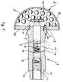
- the holder 1 consists of a sleeve 6. Inside is a Dorn 7 axially displaceably mounted.
- the mandrel 7 is actuated in the present case by an actuator in the form of a threaded bolt 14 which through an elongated hole 13 in the sleeve 6 and with the threaded bore 15th is screwed into the mandrel 6.
- the movement of the threaded bolt 14 in Figure 1 to the right causes the distal end 21 of the dome 7 to disengage comes with the balls 4, which are an essential part of the Form quick fastener 3.
- the balls 4 are an essential part of the Form quick fastener 3.
- the sleeve 6 is inserted into the interior of the sleeve 6 screwed bolt 11 closed.
- a spiral spring 12 is inserted in the present case, which points the mandrel 7 in the direction of preloads the cage housing 8.
- the tension of the spring 12 ensures that the threaded bolt 14 with the mandrel 7 in Figure 1 shifted to the left be so that the distal end 21 of the mandrel 7 between the balls 4th presses and tries to displace it from the ball housing 8. This does not succeed due to the cage situation. Rather, the balls 4 locked in position. As a result, they reach behind the permanently Undercuts 5 on the instrument 2.
- the undercuts 5 are formed by webs 17 in the equatorial plane of the instrument 2 designed as a Raffel cutter blade.
- the webs grip here through the cavity 16 of the instrument.
- the socket 11 provided with an external thread 19 unscrew the bore with the internal thread 20 in the sleeve 6.
- a conventional hexagon socket thread 22 is used in the socket 11 so-called AO key.
- the threaded bolt 14 also has a Hexagon socket thread 23 for the AO key.
- the mandrel can be removed from the inside of the sleeve 6 become.
- the balls 4 can pass through the interior of the sleeve 6 the rear end 10 of the sleeve 6 are removed.
- the assembly after the Cleaning is done in a simple manner in reverse order.
Abstract
Description
Die vorliegende Erfindung betrifft einen Halter für ein chirurgisches Instrument, der mit dem chirurgischen Instrument durch einen Schnellverschluß koppelbar ist, gemäß dem Oberbegriff des Anspruchs 1.The present invention relates to a holder for a surgical Instrument that is connected to the surgical instrument by a Quick lock can be coupled, according to the preamble of claim 1.
Derartige gattungsgemäße Halter sind beispielsweise aus der DE 39 34 610 A1 bekannt. Denkt man beispielsweise an eine Raffelfräserklinge als chirurgisches Instrument, mit der das natürliche Acetabulum zur Vorbereitung der Implantation eines Metallsockels eines künstlichen Hüftgelenkes präpariert wird, so ist beispielsweise auch ein Bajonettverschluß bekannt, wobei Stege in der Äquatorialebene der Klinge durch den Bajonettverschluß beim Verriegeln umfaßt werden. Der Verschluß ist federvorgespannt, so daß der Verschluß stets nur gegen die Federkraft geöffnet werden kann. Gerade bei der Vorbereitung des Acetabulums für die Implantation eines Metallsockels eines künstlichen Hüftgelenkes ist der Wechsel zwischen verschiedenen Größen der Raffelfräserklinge notwendig. Normalerweise wird mit der kleinsten Klinge mit dem Ausfräsen begonnen und die Größe stufenweise, beispielsweise in sieben Stufen, bis zum Maximum erhöht. Dies bedeutet einerseits, daß die Ankoppelung und die Entkoppelung des Halters vom Instrument für den Operateur leicht vonstatten gehen muß. Darüberhinaus aber muß das Instrument und der Halter nach der Operation gereinigt werden. Hierzu erscheint es bei dem bekannten Gerät als nachteilig, daß es sich nicht ohne weiteres in seine Einzelteile zerlegen läßt, die dann relativ unproblematisch gereinigt werden können. Such generic holders are for example from DE 39 34 610 A1 known. For example, if you think of a Raffel cutter blade as a surgical one Instrument used to prepare the natural acetabulum Implantation of a metal base of an artificial hip joint prepared is, for example, a bayonet lock is also known, with webs in the equatorial plane of the blade through the bayonet lock when locking be included. The breech is spring biased so that the breech can only be opened against the spring force. Especially with the Preparation of the acetabulum for the implantation of a metal base Artificial hip joint is the change between different sizes of the Raffle cutter blade necessary. Usually the smallest blade comes with started milling and the size gradually, for example in seven Levels, increased to the maximum. On the one hand, this means that the Coupling and decoupling the holder from the instrument for the Surgeon must go easily. Beyond that, however Instrument and holder are cleaned after surgery. For this it seems disadvantageous in the known device that it is not without further disassembled into its individual parts, which then relatively unproblematic can be cleaned.
Ein anderer Vorschlag sieht vor, daß der Halter an seinem Koppelungsende mit einer relativ großen Grundplatte versehen ist, auf die entsprechend ausgebildete Instrumente gesetzt werden können. Eine einfache Rastvorrichtung soll die Klinge auf der Grundplatte arretieren. Hierbei stellt es sich als problematisch heraus, daß der Kraftschluß und Formenschluß zwischen Halter und Klinge nicht groß genug ist, um den hohen auftretenden Belastungen beim Ausfräsen des Acetabulums auf Dauer standhalten zu können.Another proposal provides that the holder at its coupling end is provided with a relatively large base plate, on the corresponding trained instruments can be set. A simple locking device should lock the blade on the base plate. Here it turns out to be problematic out that the frictional connection and positive connection between the holder and blade is not big enough to withstand the high loads that occur To be able to withstand milling out of the acetabulum in the long term.
Weitere Halter für chirurgische Instrumente sind im übrigen bekannt aus der US 5 222 956 A, US 5 171 312 A, EP 0 642 770 A2.Other holders for surgical instruments are known from the rest of the US 5 222 956 A, US 5 171 312 A, EP 0 642 770 A2.
Vor dem aufgezeigten Hintergrund ist es nun die Aufgabe der vorliegenden Erfindung, einen gattungsgemäßen Halter anzugeben, der leicht zu öffnen und zu schließen ist und leicht zerlegbar und damit gut zu reinigen ist.Against the background shown, it is now the task of the present Invention to provide a generic holder that is easy to open and is to be closed and can be dismantled easily and is therefore easy to clean.
Gelöst wird diese Aufgabe dadurch, daß die Hinterschnitte von einen Hohlraum im Instrument übergreifenden Stegen als Bestandteil eines Doppel-Kreuzstegess gebildet sind.This task is solved in that the undercuts by one Crosspieces in the instrument cross-cavity as part of a double crosspiece are formed.
Das Instrument weist als Koppelelement über einen Hohlraum gespannte, die Hinterschneidung bildende Stege auf. Insbesondere wenn das Instrument eine Raffelfräserklinge ist, wird der Hohlraum gebildet durch die halbkugelförmige Innenkalotte des Fräsers. Die Stege sind dann in etwa in der Äquatorialebene gespannt.The instrument has as a coupling element stretched over a cavity, the Undercuts forming undercuts. Especially if the instrument is a Raffel cutter blade, the cavity is formed by the hemispherical Inner dome of the milling cutter. The webs are then approximately in the equatorial plane curious; excited.
Die entsprechend ausgebildete Raffelfräserklinge als Instrument in der vorbenannten Kombination ist vorzugsweise so weitergebildet, daß der Steg ein Doppelkreuzsteg in der Äquatorialebene ist. Durch die Minenöffnung des Doppelkreuzsteges wird der Halter beim Ankoppeln des Instrumentes geführt und das Betätigungsorgan wird währenddessen so betätigt, daß der Dorn im Inneren der Hülse nicht zwischen die Kugeln greift. In der Endposition des distalen Halterendes wird dann das Betätigungsorgan freigegeben, woraufhin die erwähnte Feder dafür sorgt, daß der Dorn in Richtung auf den Kugelkäfig gedrückt wird, um zwischen die Kugeln zu greifen und zu arretieren derart, daß die Kugeln den Halter aufgrund des Hintergreifens der Hinterschneidungen am Doppelkreuzsteg sicher arretieren.The appropriately trained Raffle cutter blade as an instrument in the The aforementioned combination is preferably developed so that the web is a Double crossbar is in the equatorial plane. Through the mine opening of the Double cross bar, the holder is guided when coupling the instrument and the actuator is operated so that the mandrel in the Do not reach inside the sleeve between the balls. In the end position of the The distal end of the holder is then released, whereupon the spring mentioned ensures that the mandrel towards the ball cage is pressed to grip and lock between the balls in such a way that the balls the holder due to the undercut of the undercuts Lock securely on the double crossbar.
Gemäß einer bevorzugten Ausführungsform ist vorgesehen, daß der Halter im wesentlichen aus einer Hülse besteht, in deren Inneren ein Dorn axial verschieblich gelagert ist, wobei der Dorn in vorgeschobener Lage die Kugeln in einem am distalen Ende des Halters vorgesehenen Käfiggehäuse arretiert. Zu diesem Zwecke fährt der Dorn an seinem distalen Ende zwischen die Kugeln und drückt sie auseinander, so daß die Kugeln über die Konturen des Käfiggehäuses teilweise herausragen, um so hinter die Hinterschneidungen am Instrument zu greifen. Darüberhinaus gibt der Dorn die Kugeln in seiner zurückgezogenen Lage frei, damit diese in das Innere des Käfiggehäuses fallen oder gedrückt werden können, wenn die Kugeln durch die Verengung an den Hinterschnitten aus dem Instrument herausgeführt werden. Der Dorn im Inneren der Hülse muß also mittels eines Betätigungsorgans in axialer Richtung so weit verschoben werden können, daß er sich bei Arretierung der Kugeln mit seinem distalen Ende zwischen die Kugeln schiebt und andererseits in die andere Richtung geschoben werden kann, so daß der Dorn nicht mehr zwischen die Kugeln greift.According to a preferred embodiment it is provided that the holder in consists essentially of a sleeve, inside of which a mandrel axially is slidably mounted, the mandrel in the advanced position the balls locked in a cage housing provided at the distal end of the holder. For this purpose, the mandrel travels between the at its distal end Balls and push them apart so that the balls over the contours of the Part of the cage housing protrudes so that it is behind the undercuts on the Grasping instrument. In addition, the thorn gives the balls in its withdrawn position so that they fall into the interior of the cage housing or can be pressed if the balls narrowed to the Undercuts are led out of the instrument. The thorn in The interior of the sleeve must therefore be actuated in the axial direction can be moved so far that it locks with the balls pushes its distal end between the balls and on the other hand into the other direction can be pushed so that the mandrel no longer reaches between the balls.
Vorzugsweise ist der Halter in Form einer Hülse am rückseitigen Ende mittels einer Buchse verschließbar, indem die Buchse vorzugsweise ein Außengewinde und die Hülse ein entsprechendes Innengewinde aufweist. Diese Anordnung läßt sich in einfacher Weise wieder auseinander nehmen, wenn nämlich die Buchse nach außen gewandt ein Innensechskantgewinde für einen sogenannten AO-Schlüssel aufweist, welcher im medizinischen Bereich weit verbreitet ist. The holder is preferably in the form of a sleeve at the rear end a socket can be closed by the socket preferably having an external thread and the sleeve has a corresponding internal thread. This arrangement can be taken apart again in a simple manner, namely if the An external hexagon socket for a so-called AO key, which is widely used in the medical field.
Bevorzugt wird eine Weiterbildung, bei der zwischen dem Dorn und der Buchse eine Spiralfeder eingesetzt ist, die den Dorn in Richtung auf die vorgeschobene Lage vorspannt. Wenn also die Hülse mit der Buchse verschlossen ist, drückt die Feder den Dorn in Richtung auf die Kugeln mit der Neigung, zwischen sie zu fahren und so zu arretieren. Dies hat für die Praxis den Vorteil, daß der Operateur bei Nichtbetätigung eines Betätigungsorganes sicher sein kann, daß das Instrument am distalen Ende des Halters arretiert ist.A further development is preferred in which between the mandrel and the A spiral spring is inserted, which pushes the mandrel towards the socket pre-stressed position. So if the sleeve with the socket is closed, the spring presses the mandrel towards the balls with the Tendency to drive between them and thus lock. This has for practice the advantage that the operator when not actuating an actuator can be sure that the instrument is locked at the distal end of the holder.
Als Betätigungsorgan ist vorzugsweise ein die Hülse durch ein Langloch hindurchgreifender Gewindebolzen vorgesehen, der mit einer entsprechenden Gewindebohrung im Dorn verschraubbar ist. Auch der Gewindebolzen kann nach außen hin wieder einen Innensechskant für einen AO-Schlüssel aufweisen.As the actuator is preferably a sleeve through an elongated hole penetrating threaded bolt provided with a corresponding Threaded hole can be screwed into the mandrel. The threaded bolt can also have an internal hexagon on the outside for an AO key.
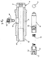
In einfacher Weise kann der erfindungsgemäße Halter nach Gebrauch zerlegt werden, nämlich indem beispielsweise zunächst der Gewindebolzen entfernt wird, die Mimik im Inneren der Hülse, also der Dorn, die Feder und die Buchse herausgenommen werden und schließlich die Kugeln durch die Hülse nach außen hin befördert werden. Die Einzelteile können sodann gereinigt und in umgekehrter Reihenfolge in ebenfalls einfacher Weise wieder zusammengefügt werden.The holder according to the invention can be dismantled in a simple manner after use are removed, namely, for example, by first removing the threaded bolt the facial expressions inside the sleeve, i.e. the mandrel, the spring and the Bush are taken out and finally the balls through the sleeve be transported to the outside. The items can then be cleaned and in the reverse order in a simple manner again be put together.
Die Erfindung wird anhand eines Ausführungsbeispieles näher erläutert. Hierbei zeigt:
- Figur 1
- den Halter mit angekoppeltem chirurgischen Instrument, im Schnitt,
Figur 2- die Einzelteile des Halters, und
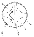
- Figur 3
- die Aufsicht auf die Unterseite auf ein chirurgisches Instrument, das mit dem Halter aus den Figuren 1 und 2 koppelbar ist.
- Figure 1
- the holder with the coupled surgical instrument, in section,
- Figure 2
- the individual parts of the holder, and
- Figure 3
- the top view of the underside of a surgical instrument that can be coupled to the holder from FIGS. 1 and 2.
Nachfolgend sind gleiche Teile mit denselben Bezugszeichen versehen.In the following, identical parts are provided with the same reference symbols.
Vorliegend besteht der Halter 1 aus einer Hülse 6. In deren Innerem ist ein
Dorn 7 axial verschieblich gelagert. Die Betätigung des Dorns 7 erfolgt
vorliegend durch ein Betätigungsorgan in Form eines Gewindebolzens 14, der
durch ein Langloch 13 in der Hülse 6 greift und mit der Gewindebohrung 15
im Dorn 6 verschraubt ist. Die Bewegung des Gewindebolzens 14 in Figur 1
nach rechts bewirkt, daß das distale Ende 21 des Doms 7 außer Eingriff
kommt mit den Kugeln 4, die einen wesentlichen Bestandteil des
Schnellverschlusses 3 bilden. Am distalen Ende 9 der Hülse 6 ist das
Käfiggehäuse 8 angeformt, in dem die Kugeln 4 gefangen sind.In the present case, the holder 1 consists of a
Am anderen Ende ist die Hülse 6 durch einen in das Innere der Hülse 6
geschraubten Bolzen 11 verschlossen. Zwischen dem Bolzen 11 und dem Dorn
7 ist vorliegend eine Spiralfeder 12 eingelegt, die den Dorn 7 in Richtung auf
das Käfiggehäuse 8 vorspannt. Läßt die Bedienerperson nun den
Gewindebolzen 14 wieder los, so sorgt die Spannung der Feder 12 dafür, daß
der Gewindebolzen 14 mit dem Dorn 7 in Figur 1 nach links verschoben
werden, so daß sich das distale Ende 21 des Dorns 7 zwischen die Kugeln 4
drückt und diese so versucht, aus dem Kugelgehäuse 8 zu verdrängen. Dies
gelingt jedoch aufgrund der Käfigsituation nicht. Vielmehr werden die Kugeln
4 in der Stellung arretiert. Hierdurch greifen sie dauerhaft hinter die
Hinterschneidungen 5 am Instrument 2. At the other end, the
Die Hinterschneidungen 5 sind gebildet durch Stege 17 in der Äquatorialebene
des als Raffelfräserklinge ausgebildeten Instrumentes 2. Die Stege greifen hier
über den Hohlraum 16 des Instrumentes.The
Die Bedienerperson braucht zum Wechsel des Instrumentes lediglich entgegen
der Kraft der Feder 12 den Gewindebolzen 14 in Figur 1 nach rechts zu
drücken, wonach der Halter 1 problemlos vom Instrument 2 abziehbar ist.The operator only needs to change the instrument
the force of the
Zur Demontage des Halters zur Reinigungszwecken ist es vorliegend lediglich
notwendig, zunächst die mit einem Außengewinde 19 versehene Buchse 11 aus
der Bohrung mit dem Innengewinde 20 in der Hülse 6 herauszuschrauben.
Hierzu dient in der Buchse 11 ein übliches Innensechskantgewinde 22 für einen
sogenannten AO-Schlüssel. Nach dem Herausschrauben der Buchse 11 kann
die Feder 12 entfernt werden. Der Gewindebolzen 14 weist ebenfalls ein
Innensechskantgewinde 23 für den AO-Schlüssel auf. Nach Entfernung des
Gewindebolzens 14 kann der Dorn aus dem Inneren der Hülse 6 entfernt
werden. Schließlich können die Kugeln 4 durch das Innere der Hülse 6 aus
dem rückseitigen Ende 10 der Hülse 6 entfernt werden. Die Montage nach der
Reinigung erfolgt in einfacher Weise in umgekehrter Reihenfolge.In the present case, it is only for dismantling the holder for cleaning purposes
necessary, first of all the
Abschließend sei auf die Aufsicht auf die Unterseite des chirurgischen
Instrumentes 2 gemäß Figur 3 hingewiesen. Hier übergreifen Stege 17 einen
Hohlraum 16 im Instrument 2. Die Stege 17 bilden hierdurch die
Hinterschnitte 5, hinter welche die Kugeln 4 des Halters 1 im arretierten
Zustand greifen und so für die sichere Befestigung des Instrumentes 2 am
Halter 1 sorgen. Vorliegend sind die Stege 17 Bestandteil eines
Doppelkreuzsteges 18. Durch die Öffnung 24 wird im dargestellten
Ausführungsbeispiel das vordere Ende des Halters 1 geschoben, so weit daß
die Kugeln 4 hinter die Stege 17 greifen.In conclusion, be sure to oversee the bottom of the
Claims (5)
Applications Claiming Priority (2)
| Application Number | Priority Date | Filing Date | Title |
|---|---|---|---|
| DE19731522A DE19731522C1 (en) | 1997-07-23 | 1997-07-23 | Surgical instrument holder |
| DE19731522 | 1997-07-23 |
Publications (3)
| Publication Number | Publication Date |
|---|---|
| EP0893097A2 true EP0893097A2 (en) | 1999-01-27 |
| EP0893097A3 EP0893097A3 (en) | 2003-05-14 |
| EP0893097B1 EP0893097B1 (en) | 2004-09-01 |
Family
ID=7836556
Family Applications (1)
| Application Number | Title | Priority Date | Filing Date |
|---|---|---|---|
| EP98113307A Expired - Lifetime EP0893097B1 (en) | 1997-07-23 | 1998-07-16 | Surgical instrument holder |
Country Status (2)
| Country | Link |
|---|---|
| EP (1) | EP0893097B1 (en) |
| DE (2) | DE19731522C1 (en) |
Cited By (8)
| Publication number | Priority date | Publication date | Assignee | Title |
|---|---|---|---|---|
| WO2001091673A1 (en) * | 2000-05-26 | 2001-12-06 | Waldemar Link (Gmbh & Co.) | Instruments used for inserting a hip cup |
| WO2002049516A1 (en) * | 2000-12-21 | 2002-06-27 | Precimed S.A. | Holder for surgical reamer |
| WO2003094753A1 (en) * | 2002-05-07 | 2003-11-20 | Depuy International Limited | An assembly for use in orthopaedic surgery |
| US7850692B2 (en) * | 2002-04-12 | 2010-12-14 | Greatbatch Medical S.A. | Minimally invasive surgical reamer and connection |
| US7909828B2 (en) | 2003-01-16 | 2011-03-22 | Greatbatch Medical S.A. | Contoured reamer teeth and method of manufacture |
| US8435243B2 (en) | 2010-02-12 | 2013-05-07 | Greatbatch Ltd. | Disposable reamer |
| EP2689730A1 (en) | 2012-07-24 | 2014-01-29 | WALDEMAR LINK GmbH & Co. KG | Holder for a medical instrument, in particular a surgical instrument |
| CN115804655A (en) * | 2023-02-09 | 2023-03-17 | 寿光市人民医院 | Clean all-in-one of nursing that operating room used |
Families Citing this family (1)
| Publication number | Priority date | Publication date | Assignee | Title |
|---|---|---|---|---|
| US11925362B2 (en) | 2021-12-10 | 2024-03-12 | Depuy Ireland Unlimited Company | Augment reamer and related methods |
Citations (4)
| Publication number | Priority date | Publication date | Assignee | Title |
|---|---|---|---|---|
| DE3934610A1 (en) | 1989-10-17 | 1991-04-25 | Aesculap Ag | QUICK COUPLING FOR SURGICAL INSTRUMENTS |
| US5171312A (en) | 1990-05-03 | 1992-12-15 | Othy, Inc. | Tool driver |
| US5222956A (en) | 1992-07-06 | 1993-06-29 | Altair Instruments, Inc. | Surgical drill collet mechanism and bur |
| EP0642770A2 (en) | 1993-07-30 | 1995-03-15 | Kaltenbach & Voigt Gmbh & Co. | Angled or straight hand-piece with a releasable chuck device for a tool, in particular for medical purposes |
Family Cites Families (4)
| Publication number | Priority date | Publication date | Assignee | Title |
|---|---|---|---|---|
| US1636421A (en) * | 1925-08-10 | 1927-07-19 | Warren E Knott | Chuck |
| US4007528A (en) * | 1975-10-22 | 1977-02-15 | Shea John J | High speed bone drill |
| DE2916221C2 (en) * | 1979-04-21 | 1980-10-30 | Aesculap-Werke Ag Vormals Jetter & Scheerer, 7200 Tuttlingen | Cranial trepan |
| DE9310668U1 (en) * | 1992-08-17 | 1993-11-04 | Leibinger Gmbh | screwdriver |
-
1997
- 1997-07-23 DE DE19731522A patent/DE19731522C1/en not_active Expired - Fee Related
-
1998
- 1998-07-16 EP EP98113307A patent/EP0893097B1/en not_active Expired - Lifetime
- 1998-07-16 DE DE59811888T patent/DE59811888D1/en not_active Expired - Fee Related
Patent Citations (4)
| Publication number | Priority date | Publication date | Assignee | Title |
|---|---|---|---|---|
| DE3934610A1 (en) | 1989-10-17 | 1991-04-25 | Aesculap Ag | QUICK COUPLING FOR SURGICAL INSTRUMENTS |
| US5171312A (en) | 1990-05-03 | 1992-12-15 | Othy, Inc. | Tool driver |
| US5222956A (en) | 1992-07-06 | 1993-06-29 | Altair Instruments, Inc. | Surgical drill collet mechanism and bur |
| EP0642770A2 (en) | 1993-07-30 | 1995-03-15 | Kaltenbach & Voigt Gmbh & Co. | Angled or straight hand-piece with a releasable chuck device for a tool, in particular for medical purposes |
Cited By (13)
| Publication number | Priority date | Publication date | Assignee | Title |
|---|---|---|---|---|
| WO2001091673A1 (en) * | 2000-05-26 | 2001-12-06 | Waldemar Link (Gmbh & Co.) | Instruments used for inserting a hip cup |
| WO2002049516A1 (en) * | 2000-12-21 | 2002-06-27 | Precimed S.A. | Holder for surgical reamer |
| US6979335B2 (en) | 2000-12-21 | 2005-12-27 | Precimed Sa | Holder for surgical reamer |
| US7850692B2 (en) * | 2002-04-12 | 2010-12-14 | Greatbatch Medical S.A. | Minimally invasive surgical reamer and connection |
| US7901405B2 (en) | 2002-04-12 | 2011-03-08 | Greatbatch Medical S.A. | Minimally invasive surgical reamer and connection |
| WO2003094753A1 (en) * | 2002-05-07 | 2003-11-20 | Depuy International Limited | An assembly for use in orthopaedic surgery |
| US7909828B2 (en) | 2003-01-16 | 2011-03-22 | Greatbatch Medical S.A. | Contoured reamer teeth and method of manufacture |
| US7922722B2 (en) | 2005-10-24 | 2011-04-12 | Greatbatch Medical S.A. | Contoured reamer teeth and method of manufacture |
| US8435243B2 (en) | 2010-02-12 | 2013-05-07 | Greatbatch Ltd. | Disposable reamer |
| EP2689730A1 (en) | 2012-07-24 | 2014-01-29 | WALDEMAR LINK GmbH & Co. KG | Holder for a medical instrument, in particular a surgical instrument |
| WO2014016011A1 (en) | 2012-07-24 | 2014-01-30 | Waldemar Link Gmbh & Co. Kg | Holder for a medical, in particular a surgical instrument |
| US9855059B2 (en) | 2012-07-24 | 2018-01-02 | Waldemar Link Gmbh & Co. Kg | Holder for a medical, in particular a surgical instrument |
| CN115804655A (en) * | 2023-02-09 | 2023-03-17 | 寿光市人民医院 | Clean all-in-one of nursing that operating room used |
Also Published As
| Publication number | Publication date |
|---|---|
| EP0893097B1 (en) | 2004-09-01 |
| EP0893097A3 (en) | 2003-05-14 |
| DE59811888D1 (en) | 2004-10-07 |
| DE19731522C1 (en) | 1999-02-11 |
Similar Documents
| Publication | Publication Date | Title |
|---|---|---|
| DE60127011T2 (en) | Tool carrier for a surgical instrument | |
| DE102004027881B4 (en) | Bone screw and osteosynthesis device | |
| DE69934267T2 (en) | Repositionable suture anchor for surgical suture | |
| DE69532080T2 (en) | BOLTS FOR SAFEGUARDING IN A BOREOILLOCH | |
| DE3611319C2 (en) | ||
| EP0028712B1 (en) | Bone cement tube removal device for use in the reimplantation of an artificial femural stem | |
| DE60013776T2 (en) | DISTRACTION / REDUCTION DEVICE FOR A SPHERICAL COLUMN OSTEOSYNTHESIS SYSTEM | |
| DE60311806T2 (en) | Clamp for attachment of Hernia mesh | |
| EP2213254B1 (en) | Surgical instrument | |
| DE1616123B1 (en) | Forceps-like surgical instrument and method for making same | |
| EP0011258A1 (en) | Device for the external fixation of the fragments of a broken bone | |
| DE19841252A1 (en) | Device for inserting bone-screw, comprising of sleeve, pulling rod and tensioning element, in particular suitable for inserting screw in distant area of body | |
| WO1991010541A1 (en) | Die chuck for multiple-cornered ends of tool spindles | |
| DE202005021315U1 (en) | Coupling device with a panic function for electromechanical locking devices | |
| WO2002019931A1 (en) | Device for fixing surgical implants | |
| EP0893097B1 (en) | Surgical instrument holder | |
| DE2246478C3 (en) | Junction connection of spatial framework constructions | |
| DE102005016869A1 (en) | Medical handpiece with a collet | |
| CH634742A5 (en) | Device for fixing bone fragments | |
| DE102005021234A1 (en) | Medical instrument | |
| WO2016046010A1 (en) | Disposable, modular surgical instrument | |
| DE202004009073U1 (en) | Bone fixing arrangement, comprising screw head DE4signed in u-shape, joined to ball-shaped top of screw | |
| DE102011105964A1 (en) | Clamping and release mechanism | |
| DE1603888A1 (en) | Self-opening and self-closing screw chuck | |
| DE4243444C2 (en) | Rasp to prepare a bone opening |
Legal Events
| Date | Code | Title | Description |
|---|---|---|---|
| PUAI | Public reference made under article 153(3) epc to a published international application that has entered the european phase |
Free format text: ORIGINAL CODE: 0009012 |
|
| AK | Designated contracting states |
Kind code of ref document: A2 Designated state(s): AT BE CH CY DE DK ES FI FR GB GR IE IT LI LU MC NL PT SE |
|
| AX | Request for extension of the european patent |
Free format text: AL;LT;LV;MK;RO;SI |
|
| PUAL | Search report despatched |
Free format text: ORIGINAL CODE: 0009013 |
|
| AK | Designated contracting states |
Designated state(s): AT BE CH CY DE DK ES FI FR GB GR IE IT LI LU MC NL PT SE |
|
| AX | Request for extension of the european patent |
Extension state: AL LT LV MK RO SI |
|
| RIC1 | Information provided on ipc code assigned before grant |
Ipc: 7A 61B 17/16 B Ipc: 7A 61B 17/00 A |
|
| 17P | Request for examination filed |
Effective date: 20030717 |
|
| AKX | Designation fees paid |
Designated state(s): CH DE ES FR GB IT LI |
|
| GRAP | Despatch of communication of intention to grant a patent |
Free format text: ORIGINAL CODE: EPIDOSNIGR1 |
|
| 17Q | First examination report despatched |
Effective date: 20040113 |
|
| GRAS | Grant fee paid |
Free format text: ORIGINAL CODE: EPIDOSNIGR3 |
|
| GRAA | (expected) grant |
Free format text: ORIGINAL CODE: 0009210 |
|
| AK | Designated contracting states |
Kind code of ref document: B1 Designated state(s): CH DE ES FR GB IT LI |
|
| PG25 | Lapsed in a contracting state [announced via postgrant information from national office to epo] |
Ref country code: IT Free format text: LAPSE BECAUSE OF FAILURE TO SUBMIT A TRANSLATION OF THE DESCRIPTION OR TO PAY THE FEE WITHIN THE PRESCRIBED TIME-LIMIT;WARNING: LAPSES OF ITALIAN PATENTS WITH EFFECTIVE DATE BEFORE 2007 MAY HAVE OCCURRED AT ANY TIME BEFORE 2007. THE CORRECT EFFECTIVE DATE MAY BE DIFFERENT FROM THE ONE RECORDED. Effective date: 20040901 Ref country code: GB Free format text: LAPSE BECAUSE OF FAILURE TO SUBMIT A TRANSLATION OF THE DESCRIPTION OR TO PAY THE FEE WITHIN THE PRESCRIBED TIME-LIMIT Effective date: 20040901 Ref country code: FR Free format text: LAPSE BECAUSE OF FAILURE TO SUBMIT A TRANSLATION OF THE DESCRIPTION OR TO PAY THE FEE WITHIN THE PRESCRIBED TIME-LIMIT Effective date: 20040901 |
|
| REG | Reference to a national code |
Ref country code: GB Ref legal event code: FG4D Free format text: NOT ENGLISH |
|
| REG | Reference to a national code |
Ref country code: CH Ref legal event code: EP |
|
| REG | Reference to a national code |
Ref country code: IE Ref legal event code: FG4D Free format text: GERMAN |
|
| REF | Corresponds to: |
Ref document number: 59811888 Country of ref document: DE Date of ref document: 20041007 Kind code of ref document: P |
|
| PG25 | Lapsed in a contracting state [announced via postgrant information from national office to epo] |
Ref country code: ES Free format text: LAPSE BECAUSE OF FAILURE TO SUBMIT A TRANSLATION OF THE DESCRIPTION OR TO PAY THE FEE WITHIN THE PRESCRIBED TIME-LIMIT Effective date: 20041212 |
|
| GBV | Gb: ep patent (uk) treated as always having been void in accordance with gb section 77(7)/1977 [no translation filed] |
Effective date: 20040901 |
|
| REG | Reference to a national code |
Ref country code: IE Ref legal event code: FD4D |
|
| PLBE | No opposition filed within time limit |
Free format text: ORIGINAL CODE: 0009261 |
|
| STAA | Information on the status of an ep patent application or granted ep patent |
Free format text: STATUS: NO OPPOSITION FILED WITHIN TIME LIMIT |
|
| PG25 | Lapsed in a contracting state [announced via postgrant information from national office to epo] |
Ref country code: LI Free format text: LAPSE BECAUSE OF NON-PAYMENT OF DUE FEES Effective date: 20050731 Ref country code: CH Free format text: LAPSE BECAUSE OF NON-PAYMENT OF DUE FEES Effective date: 20050731 |
|
| 26N | No opposition filed |
Effective date: 20050602 |
|
| EN | Fr: translation not filed | ||
| REG | Reference to a national code |
Ref country code: CH Ref legal event code: PL |
|
| PGFP | Annual fee paid to national office [announced via postgrant information from national office to epo] |
Ref country code: DE Payment date: 20060802 Year of fee payment: 9 |
|
| PG25 | Lapsed in a contracting state [announced via postgrant information from national office to epo] |
Ref country code: DE Free format text: LAPSE BECAUSE OF NON-PAYMENT OF DUE FEES Effective date: 20080201 |
|
| REG | Reference to a national code |
Ref country code: DE Ref legal event code: R081 Ref document number: 59811888 Country of ref document: DE Owner name: ORTHODYNAMICS GMBH, DE Free format text: FORMER OWNER: ESKA IMPLANTS GMBH & CO.KG, 23556 LUEBECK, DE Effective date: 20110707 |
|
| REG | Reference to a national code |
Ref country code: DE Ref legal event code: R082 Ref document number: 59811888 Country of ref document: DE Representative=s name: DEHNS, GB |