EP0825464B1 - Process of manufacturing and assembling a collective optical coupling device onto the end of a bundle of several monomode optical fibers - Google Patents
Process of manufacturing and assembling a collective optical coupling device onto the end of a bundle of several monomode optical fibers Download PDFInfo
- Publication number
- EP0825464B1 EP0825464B1 EP97401942A EP97401942A EP0825464B1 EP 0825464 B1 EP0825464 B1 EP 0825464B1 EP 97401942 A EP97401942 A EP 97401942A EP 97401942 A EP97401942 A EP 97401942A EP 0825464 B1 EP0825464 B1 EP 0825464B1
- Authority
- EP
- European Patent Office
- Prior art keywords
- fibres
- fiber
- index
- lengths
- optical
- Prior art date
- Legal status (The legal status is an assumption and is not a legal conclusion. Google has not performed a legal analysis and makes no representation as to the accuracy of the status listed.)
- Expired - Lifetime
Links
Images


Classifications
-
- G—PHYSICS
- G02—OPTICS
- G02B—OPTICAL ELEMENTS, SYSTEMS OR APPARATUS
- G02B6/00—Light guides; Structural details of arrangements comprising light guides and other optical elements, e.g. couplings
- G02B6/24—Coupling light guides
- G02B6/255—Splicing of light guides, e.g. by fusion or bonding
- G02B6/2552—Splicing of light guides, e.g. by fusion or bonding reshaping or reforming of light guides for coupling using thermal heating, e.g. tapering, forming of a lens on light guide ends
-
- G—PHYSICS
- G02—OPTICS
- G02B—OPTICAL ELEMENTS, SYSTEMS OR APPARATUS
- G02B6/00—Light guides; Structural details of arrangements comprising light guides and other optical elements, e.g. couplings
- G02B6/24—Coupling light guides
- G02B6/26—Optical coupling means
- G02B6/32—Optical coupling means having lens focusing means positioned between opposed fibre ends
-
- G—PHYSICS
- G02—OPTICS
- G02B—OPTICAL ELEMENTS, SYSTEMS OR APPARATUS
- G02B6/00—Light guides; Structural details of arrangements comprising light guides and other optical elements, e.g. couplings
- G02B6/24—Coupling light guides
- G02B6/42—Coupling light guides with opto-electronic elements
- G02B6/4201—Packages, e.g. shape, construction, internal or external details
- G02B6/4202—Packages, e.g. shape, construction, internal or external details for coupling an active element with fibres without intermediate optical elements, e.g. fibres with plane ends, fibres with shaped ends, bundles
- G02B6/4203—Optical features
-
- G—PHYSICS
- G02—OPTICS
- G02B—OPTICAL ELEMENTS, SYSTEMS OR APPARATUS
- G02B6/00—Light guides; Structural details of arrangements comprising light guides and other optical elements, e.g. couplings
- G02B6/24—Coupling light guides
- G02B6/42—Coupling light guides with opto-electronic elements
- G02B6/4201—Packages, e.g. shape, construction, internal or external details
- G02B6/4249—Packages, e.g. shape, construction, internal or external details comprising arrays of active devices and fibres
Definitions
- the present invention relates to a method of manufacturing and assembling a collective optical coupling device on the end of a bundle of several single-mode fibers, in order to allow the optical coupling of said single mode fibers with an optoelectronic module.
- the field of the invention is that of optical telecommunications and more particularly that of distribution networks which concern short distance links and require effort important in terms of cost both in terms of infrastructure as end components.
- the wavelength is most often 1.3 or 1.55 ⁇ m.
- optical coupling constitutes a step of which it is necessary to lower the cost.
- One solution is to treat this step collectively.
- the difficulty is twofold: on the one hand it is linked to the mismatch in the shape and size of the modes optics of the elements to be coupled, on the other positioning details which are submicron.
- the coupled power drops by 1 dB when moving away from a distance less than micrometer of the optimal position in the plane perpendicular to the optical axis, and a few micrometers ( ⁇ m) on the optical axis.
- the passive assembly between bars of fiber components and combs, which consists of position the different elements without feeding the components, is difficult to achieve.
- K. SHIRAISHI et al. offer in particular a lens consisting of a fiber section without end core hemispherical, obtained by micro-machining, welded to a single mode fiber with locally enlarged core by heating.
- the coupling rates obtained were with severe positioning tolerances.
- Document WO-A-86 04156 describes an optical coupling device between a single mode fiber and an optoelectronic module.
- the coupling device comprises a lens formed of a cylindrical section of index gradient fiber having a diameter 125 ⁇ m exterior tuned to single-mode fiber.
- the Patent Abstracts of Japan document summarizing the Japanese patent application for publication number JP-58202413 describes an optical coupling device between a single mode fiber and a laser.
- the coupling device present comprises a lens and a section of silica fiber placed between the single-mode fiber and the lens.
- the fiber stretch silica thus arranged improves the coupling between the laser and the single mode optical fiber.
- the coupling device comprises a fiber bar silica. This device is soldered to one end of the optical fiber and cut to a length defined. The free end is rounded off by heat treatment. The length of the coupling device is greater than the diameter of the single mode fiber.
- Document EP-A-0 531 225 describes a method of cleaving an optical fiber intended to obtain an oblique face at the end of an optical fiber. Two points of the fiber optics are moved transversely relative to each other and a fracture initiator is made in the fiber between the displaced points. This process is particularly applied to an optical fiber with a diameter of 125 ⁇ m. The process described is also applicable to the cleavage of a plurality of optical fibers.
- the first object of the present invention is to propose a method for manufacturing a coupling allowing the tolerances to be relaxed fiber positioning on the optical axis and in the perpendicular plane of this axis.
- the sections of silica are replaced by any type of fiber of suitable index, a fiber with index jump for example.
- an optical coupling device will also be described between minus a single-mode fiber and an optoelectronic module, comprising at least one lens, in which each lens is formed by a cylindrical section fiber with an index gradient of 125 ⁇ m in diameter exterior, not covered by the present invention.
- a process includes the assembly steps, to a ribbon of single-mode fibers 10, a multimode fiber ribbon with a gradient of index 20 and fracture of index gradient fibers.
- An embodiment of the method according to the invention includes (Fig. 2A-2J) the steps for assembling a fiber ribbon multimode gradient index 20 to a ribbon of fibers silica 30, fracture of silica fibers 30, assembly of this set to a ribbon of monomode fibers 10 and finally fiber fracture of the multimode fiber ribbon to index gradient 20 extended by sections of silica fiber.
- the beams propagate periodically following the optical axis. This is due to lateral refractions successive periods undergone by the electromagnetic wave when propagated in an index medium which decreases from the center of the fiber to the periphery.
- the period P (often called pitch) depends on the profile fiber index, which follows a parabolic law, and the wavelength of the light propagating there.
- the mode adaptation between the object and the image is made thanks to the fiber section with gradient index of the same way as with a gradient lens of standard plane-plane index (10).
- silica The role of silica is to spatially extend the light beam at the output of single mode fiber. This extension allows to use all the volume of the gradient index. The index gradient segment is then best used as a lens since the occupancy volume of the light beam is equal to volume of the index gradient.
- silica sections could be replaced by sections of fibers of suitable index, fibers with hint hints for example
- Figure 3 qualitatively illustrates the beam propagation difference with and without section of silica between the single mode fiber and the gradient index lens. (NB: the actual odds do not are not respected)
- the silica sections can have a zero length, in which case the index gradient fiber ribbon is directly soldered to the ribbon of single-mode fibers.
- the maximum mode diameter is of the order of 28 ⁇ m for a length of index gradient of P / 4 (ie 365 ⁇ m), the working distance is then zero.
- the maximum distance between fibers is 460 ⁇ m, for an associated mode diameter of 20 ⁇ m.
- the maximum mode diameter is 80 ⁇ m instead of 28 and the maximum distance between fibers is 1.8 mm instead of 460 ⁇ m.
- the loss of coupling being equivalent in both cases (0.5 db).
- optical coupling devices produced according to the method of the invention have several applications in transmitter or receiver modules multichannel in the field of telecommunications by optical fiber.
- This optical system is compatible in particular with a passive collective assembly on PIN photodiode array silicon platform or semiconductor lasers in front of ribbons single mode fibers.
- connectors high-performance and highly aligned multi-path connectors tolerant.
- the multimode gradient fiber section index only soldered at the end of single-mode fiber does not allow not to adapt the diameter of the mode at the optical output to that of the laser (approximately 2 ⁇ m). Indeed, this diameter does not cannot go below 10 ⁇ m, and this for a length of P / 2 index gradient, i.e. 730 ⁇ m.
- the silica section typically of 500 ⁇ m between the index gradient lens (typically 400 ⁇ m in length) and the single-mode fiber, a mode diameter is obtained at the optical output adapted to that of the laser.
- This improves the coupling performance, the losses typically go from 10 to 4.5 db for lasers with 1.6 ⁇ m mode diameter. It is a very good performance for optics produced by a simple entirely collective process.
- the laser-fiber working distance is of the order of 50 ⁇ m, instead of contact for the cleaved fiber or the section with a pure index gradient.
- Figure 4 shows the block diagram of coupling between a laser strip and a ribbon of single mode fibers provided with a device according to the invention.
- angles of divergence as well as the mode rays of the Gaussian beam of the laser measured at 1 / e 2 of the maximum intensity in the planes parallel and perpendicular to the plane of the junction of the laser are the following:
- the coupling losses between the laser described above and the optical device presented in table T2 are 3.9 dB, for a working distance of 63 ⁇ m (T2) I (microns) L (microns) working distance ( ⁇ m) coupling losses (dB) tolerances in x and y at -1dB ( ⁇ m) tolerance in z at -1 dB ( ⁇ m) 1063 330 63 3.9 ⁇ 1.1 ⁇ 6
- the coupling efficiency between the same laser and a cleaved single-mode fiber is 9.1 dB for a working distance of 20 ⁇ m, it is 12 dB for a working distance of 63 ⁇ m.
- the Gaussian beam of the cleaved single-mode fiber used has a symmetry of revolution and a fashion radius 4.5 ⁇ m, or a half angle of divergence of 5.2 °.
- the cleaved fiber should be in contact with the laser to get the least loss, 8.6 dB, but you can't place it there without damaging the laser.
- the illustrated device therefore makes it possible to reduce coupling losses compared to a fiber cleaved placed at best and increase the distance of 63 ⁇ m work.
- the optical coupling device makes it possible to obtain the illumination of PIN photodiodes.
- the optical device described in table T3 allows you to move the focus point back from 0 to 200 ⁇ m and increase the mode diameter from 9 to 12 ⁇ m, compared to a cleaved fiber.
- optical coupling device has been represented schematically on the Figure 5 in a fiber connector application fiber, and is not covered by the claims.
- positioning tolerances at -1 dB in the plane perpendicular to the optical axis between two fibers of the device are ⁇ 5 ⁇ m against ⁇ 1.5 ⁇ m between two cleaved fibers.
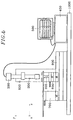
- optical devices are produced according to the process using a standard tape welder and the fractures of the sections of precise length are carried out well on the bench shown in Figure 6.
- the video microscope 300 is connected to a camera 300 whose image is displayed on a video monitor 500 after processing by a 400 distance measurement system. system projects lines that we can move on the screen and allows, with prior calibration, measure distances.
- the fracturing pliers 10 can move according to three directions x, y and z using block 600 including 3 manual displacement stages micrometric, itself fixed to the rail 900 by through a jumper.
- Alignment between the welding plane and the trace of the knife is done visually using the video microscope.
- the displacement of the ribbon is adjusted to the desired dimension thanks to the 400 measurement system.
- the video microscope is maintained by a gallows 800, the whole and supported by a stable base 1000.
Description
La présente invention concerne un procédé de fabrication et d'assemblage d'un dispositif de couplage optique collectif sur l'extrémité d'un faisceau de plusieurs fibres monomodes, en vue de permettre le couplage optique desdites fibres monomodes avec un module optoélectronique.The present invention relates to a method of manufacturing and assembling a collective optical coupling device on the end of a bundle of several single-mode fibers, in order to allow the optical coupling of said single mode fibers with an optoelectronic module.
Le domaine de l'invention est celui des télécommunications optiques et plus particulièrement celui des réseaux de distribution qui concernent des liaisons de courte distance et nécessitent des efforts importants en terme de coût tant au niveau des infrastructures que des composants d'extrémité. Dans le domaine des télécommunications, la longueur d'onde est le plus souvent 1,3 ou 1,55 µm.The field of the invention is that of optical telecommunications and more particularly that of distribution networks which concern short distance links and require effort important in terms of cost both in terms of infrastructure as end components. In the telecommunications field, the wavelength is most often 1.3 or 1.55 µm.
L'assemblage de modules optoélectroniques appelé couplage optique constitue une étape dont il est nécessaire d'abaisser le coût. Une solution consiste à traiter cette étape de manière collective. La difficulté est double : d'une part elle est liée à la désadaptation de la forme et de la taille des modes optiques des éléments à coupler, d'autre part aux précisions de positionnement qui sont submicroniques.The assembly of optoelectronic modules called optical coupling constitutes a step of which it is necessary to lower the cost. One solution is to treat this step collectively. The difficulty is twofold: on the one hand it is linked to the mismatch in the shape and size of the modes optics of the elements to be coupled, on the other positioning details which are submicron.
En effet, la puissance couplée chute de 1 dB lorsque l'on s'éloigne d'une distance inférieure au micromètre de la position optimale dans le plan perpendiculaire à l'axe optique, et de quelques micromètres (µm) sur l'axe optique. On sait positionner les éléments à coupler en dynamique, c'est-à-dire en ajustant en temps réel le positionnement en fonction du taux de couplage. Mais l'assemblage passif entre barrettes de composants et peignes de fibres, qui consiste à positionner les différents éléments sans alimenter les composants, est difficile à réaliser. Indeed, the coupled power drops by 1 dB when moving away from a distance less than micrometer of the optimal position in the plane perpendicular to the optical axis, and a few micrometers (µm) on the optical axis. We know how to position the elements to couple in dynamics, that is to say by adjusting in real-time positioning according to the rate of coupling. But the passive assembly between bars of fiber components and combs, which consists of position the different elements without feeding the components, is difficult to achieve.
Pour résoudre le problème du couplage laser-fibre, l'utilisation d'une micro lentille a été proposé. K. SHIRAISHI et al. proposent en particulier une lentille constituée d'un tronçon de fibre sans coeur d'extrémité hémisphérique, obtenue par micro-usinage, soudé à une fibre monomode dont le coeur a été localement élargi par chauffage. Les taux de couplage obtenus l'ont été avec des tolérances de positionnement sévères. Ces solutions sont complexes à mettre en oeuvre et difficilement compatibles avec un traitement collectif sur rubans de fibres par exemple.To solve the problem of laser-fiber coupling, the use of a micro lens has been proposed. K. SHIRAISHI et al. offer in particular a lens consisting of a fiber section without end core hemispherical, obtained by micro-machining, welded to a single mode fiber with locally enlarged core by heating. The coupling rates obtained were with severe positioning tolerances. These solutions are complex to implement and hardly compatible with collective treatment on fiber ribbons for example.
Le document WO-A-86 04156 décrit un dispositif de couplage optique entre une fibre monomode et un module optoélectronique. Le dispositif de couplage comprend une lentille formée d'un tronçon cylindrique de fibre à gradient d'indice présentant un diamètre extérieur de 125 µm accordé à la fibre monomode.Document WO-A-86 04156 describes an optical coupling device between a single mode fiber and an optoelectronic module. The coupling device comprises a lens formed of a cylindrical section of index gradient fiber having a diameter 125 µm exterior tuned to single-mode fiber.
Le document Patent Abstracts of Japan résumant la demande de brevet japonaise de numéro de publication JP-58202413 décrit un dispositif de couplage optique entre une fibre monomode et un laser. Le dispositif de couplage présente comprend une lentille et un tronçon de fibre de silice disposé entre la fibre monomode et la lentille. Le tronçon de fibre de silice ainsi disposé améliore le couplage entre le laser et la fibre optique monomode.The Patent Abstracts of Japan document summarizing the Japanese patent application for publication number JP-58202413 describes an optical coupling device between a single mode fiber and a laser. The coupling device present comprises a lens and a section of silica fiber placed between the single-mode fiber and the lens. The fiber stretch silica thus arranged improves the coupling between the laser and the single mode optical fiber.
Le document Patent Abstracts of Japan résumant la demande de brevet japonaise de numéro de publication JP-03189607 décrit un dispositif de couplage optique pour fibre optique monomode. Un tronçon de fibre optique multimodes d'une longueur approximative de 1 mm est couplé à un tronçon de fibre optique monomode. L'extrémité du tronçon de fibre optique multimodes est attaquée chimiquement sélectivement pour réaliser une lentille sphérique. La forme de la lentille est déterminée en fonction de l'indice de réfraction du coeur de la fibre.The Patent Abstracts of Japan document summarizing the Japanese patent application for publication number JP-03189607 describes an optical coupling device for fiber single mode optics. An approximate length of multimode optical fiber of 1 mm is coupled to a section of single-mode optical fiber. The end of the stretch of multimode optical fiber is chemically selectively attacked to achieve spherical lens. The shape of the lens is determined according to the index of refraction of the fiber core.
Le document US-A-4 456 330 décrit un dispositif de couplage optique d'une fibre optique monomode à un laser. Le dispositif de couplage comprend une barre en fibre de silice. Ce dispositif est soudé à une extrémité de la fibre optique et coupé à une longueur définie. L'extrémité libre est arrondie par un traitement thermique. La longueur du dispositif de couplage est supérieure au diamètre de la fibre monomode.Document US-A-4,456,330 describes an optical fiber coupling device single mode optics to a laser. The coupling device comprises a fiber bar silica. This device is soldered to one end of the optical fiber and cut to a length defined. The free end is rounded off by heat treatment. The length of the coupling device is greater than the diameter of the single mode fiber.
Le document Journal of Optical Communications, Vol 10, N°2, Juin 1989, pages
61-66, décrit un procédé d'assemblage de deux faisceaux présentant chacun plusieurs fibres
optiques monomodes. Ce document permet de réduire les pertes au niveau de l'épissure
entre des fibres monomodes. Le procédé comprend la traction de l'épissure sur une certaine
course après l'assemblage des deux faisceaux. Le document définit des calculs des courses
de traction optimales.The document Journal of Optical Communications,
Le document EP-A-0 531 225 décrit un procédé de clivage d'une fibre optique destiné à obtenir une face oblique à l'extrémité d'une fibre optique. Deux points de la fibre optique sont déplacés transversalement l'un par rapport à l'autre et une amorce de rupture est réalisée dans la fibre entre les points déplacés. Ce procédé est notamment appliqué à une fibre optique d'un diamètre de 125µm. Le procédé décrit est également applicable au clivage d'une pluralité de fibres optiques.Document EP-A-0 531 225 describes a method of cleaving an optical fiber intended to obtain an oblique face at the end of an optical fiber. Two points of the fiber optics are moved transversely relative to each other and a fracture initiator is made in the fiber between the displaced points. This process is particularly applied to an optical fiber with a diameter of 125µm. The process described is also applicable to the cleavage of a plurality of optical fibers.
La présente invention a pour premier objet de proposer un procédé de fabrication d'un dispositif de couplage permettant de relâcher les tolérances de positionnement des fibres sur l'axe optique et dans le plan perpendiculaire de cet axe.The first object of the present invention is to propose a method for manufacturing a coupling allowing the tolerances to be relaxed fiber positioning on the optical axis and in the perpendicular plane of this axis.
Toutes les étapes de réalisation du procédé selon l'invention sont entièrement collectives. En effet, selon l'invention, on manipule uniquement des rubans de fibres tout au long du procédé, et toutes les fibres d'un même ruban subissent les mêmes opérations au même moment. L'avantage est multiple, non seulement en terme économique, en particulier par le gain de temps de fabrication et d'assemblage que procure un traitement collectif par rapport à un traitement individuel, mais aussi en terme d'homogénéité des micro-optiques obtenues en bout de ruban.All stages of carrying out the process according to the invention are entirely collective. Indeed, according to the invention, only ribbons of fibers throughout the process, and all of the fibers of the same ribbon undergo the same operations at the same moment. The advantage is multiple, not only in terms economical, in particular by saving time manufacturing and assembly that provides treatment collective versus individual treatment, but also in terms of homogeneity of micro-optics obtained at the end of the ribbon.
La simplicité du procédé proposé procure à nos optiques leur caractère économique et reproductible. En effet, celui-ci ne comprend que des opérations simples telles que le dénudage, le clivage, et la soudure qui rend le procédé reproductible. The simplicity of the proposed process gives our their economic and reproducible nature. In effect, this one only includes simple operations such as stripping, cleavage, and soldering which makes the process reproducible.
Une solution à ce poblème consiste à mettre
en oeuvre un procédé de fabrication et d'assemblage d'un dispositif de
couplage optique sur l'extrémité d'un faisceau de plusieurs fibres monomodes,
tel que défini à la revendication 1.One solution to this problem is to put
implement a method of manufacturing and assembling a device
optical coupling on the end of a bundle of several single-mode fibers,
as defined in
Selon un autre mode de réalisation, les tronçons de silice sont remplacés par tout type de fibre d'indice adapté, une fibre à saut d'indice par exemple. According to another embodiment, the sections of silica are replaced by any type of fiber of suitable index, a fiber with index jump for example.
Selon un mode préférentiel de mise en oeuvre du procédé objet de l'invention, les faisceaux de fibre ont une structure sous forme d'au moins un ruban ;
- Dans une application de mise en oeuvre du procédé le module optoélectronique est constitué de composants actifs dont le nombre correspond au nombre de fibres à coupler.
- Ces composants actifs sont soit des lasers soit des photodiodes.
- In an application for implementing the method, the optoelectronic module consists of active components, the number of which corresponds to the number of fibers to be coupled.
- These active components are either lasers or photodiodes.
A titre illustratif, on décrira également un dispositif de couplage optique entre au moins une fibre monomode et un module optoélectronique, comportant au moins une lentille, dans lequel chaque lentille est formée par un tronçon cylindrique de fibre à gradient d'indice de 125 µm de diamètre extérieur, non couvert par la présente invention.By way of illustration, an optical coupling device will also be described between minus a single-mode fiber and an optoelectronic module, comprising at least one lens, in which each lens is formed by a cylindrical section fiber with an index gradient of 125 µm in diameter exterior, not covered by the present invention.
Ce dispositif peut en outre comporter, entre la fibre monomode et la lentille, un tronçon de fibre de silice destiné à placer la fibre monomode à la bonne distance de la lentille et/ou à adapter l'indice du milieu de propagation de la fibre monomode à celui de la lentille ;
- Dans le cas où le dispositif réalise un couplage entre plusieurs fibres monomodes et un module optoélectronique, les fibres monomodes sont dans une structure sous forme de ruban ;
- Selon certaines applications, le module
électronique est composé d'un ensemble de composants
actifs ;
- les composants actifs sont des lasers ;
- les composants actifs sont des photodiodes ;
- Pour d'autres applications, le module électronique est composé soit d'une fibre monomode soit d'un faisceau de fibres, le dispositif servant alors à coupler des fibres optiques entre-elles ;
- Selon un mode préféré de réalisation, les fibres sont structurées sous forme d'au moins un ruban.
- In the case where the device performs a coupling between several single-mode fibers and an optoelectronic module, the single-mode fibers are in a ribbon-like structure;
- According to certain applications, the electronic module is composed of a set of active components;
- the active components are lasers;
- the active components are photodiodes;
- For other applications, the electronic module is composed either of a single-mode fiber or of a bundle of fibers, the device then serving to couple optical fibers together;
- According to a preferred embodiment, the fibers are structured in the form of at least one ribbon.
Les avantages procurés par l'invention seront
mieux compris au travers de la description suivante qui
se réfère aux dessins annexés qui illustrent
l'invention sans caractère limitatif et sur lesquels :
La description qui est faite ci-après est faite à partir de faisceaux de fibres se présentant sous la forme de rubans à l'intérieur desquels les fibres sont alignées et espacées régulièrement. La technologie de fabrication de tels rubans est bien connue aujourd'hui et ne sera pas plus détaillée. On parlera donc dans toute la suite de rubans de fibres plutôt que de faisceaux.The description which is made below is given to from bundles of fibers under the form of ribbons inside which the fibers are aligned and spaced regularly. Technology manufacture of such ribbons is well known today and will not be further detailed. We will therefore speak in the whole string of fiber ribbons rather than beams.
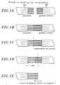
Un procédé (Fig. 1A-1E) comporte
les étapes d'assemblage, à un ruban de fibres monomodes 10,
d'un ruban de fibres multimodes à gradient d'indice 20 et de
fracture des fibres à gradient d' indice.A process (Fig. 1A-1E) includes
the assembly steps, to a ribbon of single-
La séquence d'étapes de ce procédé n'est pas couverte par les revendications.The sequence of steps of this process is not covered by the claims.
Les détails de réalisation de ces étapes sont illustrés respectivement par les figures 1A à 1C et 1D, 1E :
- Mise en place et alignement des deux rubans de
fibres 10 et 20 dans la soudeuse, (1A) - Soudure des fibres des deux rubans 10, 20, (1B)
- Alignement du plan de soudure avec la trace du plan de fracture, 1C
- Déplacement de l'ensemble d'une distance L et amorce de fracture, 1D
- Fracture du ruban de fibres multimodes à gradient d'indice, 1E.
- Installation and alignment of the two
fiber ribbons - Soldering of the fibers of the two
tapes - Alignment of the weld plane with the trace of the fracture plane, 1C
- Displacement of the whole of a distance L and fracture initiation, 1D
- Gradient index multimode fiber ribbon fracture, 1E.
Un mode de réalisation du procédé selon l'invention
comporte (Fig. 2A-2J) les étapes d'assemblage d'un ruban de fibres
multimodes à gradient d'indice 20 à un ruban de fibres
silice 30, fracture des fibres de silice 30, assemblage de
cet ensemble à un ruban de fibres monomodes 10 et enfin
fracture des fibres du ruban de fibres multimodes à
gradient d'indice 20 prolongées par des sections de fibre en silice.An embodiment of the method according to the invention
includes (Fig. 2A-2J) the steps for assembling a fiber ribbon
Les détails de réalisation de ces étapes sont illustrés respectivement par les figures 2A à 2C ; 2D, 2E ; 2F à 2I et 2J :
- dénudage et clivage des rubans de silice 30 et
de fibres multimodes à
gradient d'indice 20 et mise en place dans une soudeuse à structure périodique en V selon un pas correspondant au pas du ruban utilisé, 250 µm par exemple, chaque V correspondant au diamètre extérieur d'une fibre soit 125 µm par exemple. (figure 2A) - soudage du ruban de fibres de silice 30 au ruban de fibres à gradient d'indice 20 (2B),
- Alignement du plan de soudure avec la trace du plan de fracture (2C),
- Translation de l'ensemble sur une
distance 1 puis amorce de la fracture (2D). - Fracture des fibres du ruban de fibres de silice à l'aide d'un banc de fracture de manière à réaliser n tronçons de silice de longueur l, n étant le nombre de fibres comprises dans le ruban.
- Reproduction de ces étapes sur l'ensemble ainsi réalisé et un ruban de fibres monomodes 10. On obtient ainsi un dispositif de couplage optique collectif constitué de tronçons cylindriques de fibres à continuité de forme de bout en bout :
- Mise en place et alignement des rubans 10
et 20 dans la soudeuse, (2G) - Soudure des fibres monomodes aux tronçons de silice 31, (2G)
- Alignement du plan de soudure avec le plan de fracture, (2H)
- Déplacement de l'ensemble d'une distance L et amorce de fracture, (2I)
- Fracture du ruban de fibres multimodes à gradient d'indice. (2J)
- stripping and cleavage of
silica ribbons 30 and multimode fibers withindex gradient 20 and placement in a welder with periodic V-structure according to a pitch corresponding to the pitch of the ribbon used, 250 μm for example, each V corresponding to the diameter outside of a fiber, for example 125 µm. (Figure 2A) - welding the
silica fiber tape 30 to the gradient index fiber tape 20 (2B), - Alignment of the weld plane with the trace of the fracture plane (2C),
- Translation of the whole over a
distance 1 then initiation of the fracture (2D). - Fracture of the fibers of the silica fiber ribbon using a fracture bench so as to produce n sections of silica of length l, n being the number of fibers included in the ribbon.
- Reproduction of these steps on the assembly thus produced and a ribbon of
monomode fibers 10. A collective optical coupling device is thus obtained consisting of cylindrical sections of fibers with continuity of shape from end to end: - Installation and alignment of
ribbons - Soldering of single-mode fibers to
silica sections 31, (2G) - Alignment of the weld plane with the fracture plane, (2H)
- Displacement of the whole of a distance L and fracture initiation, (2I)
- Gradient index multimode fiber ribbon fracture. (2J)
Principe de fonctionnement des dispositifs de couplage obtenu par ce procédé : Operating principle of the coupling obtained by this process:
Dans une fibre multimode à gradient d'indice, les faisceaux se propagent de manière périodique suivant l'axe optique. Ceci est dû aux réfractions latérales successives subies par l'onde électromagnétique lorsqu'elle se propage dans un milieu d'indice qui décroít du centre de la fibre vers la périphérie. La période P (souvent appelée pitch) dépend du profil d'indice de la fibre, qui suit une loi parabolique, et de la longueur d'onde de la lumière qui s'y propage.In a multimode fiber with an index gradient, the beams propagate periodically following the optical axis. This is due to lateral refractions successive periods undergone by the electromagnetic wave when propagated in an index medium which decreases from the center of the fiber to the periphery. The period P (often called pitch) depends on the profile fiber index, which follows a parabolic law, and the wavelength of the light propagating there.
Lorsqu'on coupe un tronçon de fibre multimode à gradient d'indice, on obtient une lentille dont les propriétés dépendent de sa longueur L, que l'on définit en fraction de P, (soit L = P/4, P/2, 3P/2, plus généralement xP, x étant un réel quelconque), du profil du gradient d'indice de la fibre et de la longueur d'onde de travail.When cutting a section of multimode fiber to gradient index, we get a lens whose properties depend on its length L, which we define as a fraction of P, (i.e. L = P / 4, P / 2, 3P / 2, plus generally xP, x being any real), of the profile the fiber index gradient and the length working wave.
L'adaptation de mode entre l'objet et l'image se fait grâce au tronçon de fibre à gradient d'indice de la même manière qu'avec une lentille à gradient d'indice plan-plan classique (10).The mode adaptation between the object and the image is made thanks to the fiber section with gradient index of the same way as with a gradient lens of standard plane-plane index (10).
Le rôle de la silice est d'étendre spacialement le faisceau lumineux en sortie de fibre monomode. Cette extension permet d'utiliser tout le volume du gradient d'indice. Le tronçon de gradient d'indice est alors exploité au mieux en tant que lentille puisque le volume d'occupation du faisceau lumineux est égale au volume du gradient d'indice.The role of silica is to spatially extend the light beam at the output of single mode fiber. This extension allows to use all the volume of the gradient index. The index gradient segment is then best used as a lens since the occupancy volume of the light beam is equal to volume of the index gradient.
Les tronçons de silice pourraient être remplacés par des tronçons de fibres d'indice adapté, des fibres à saut d'indices par exempleThe silica sections could be replaced by sections of fibers of suitable index, fibers with hint hints for example
La figure 3 illustre de manière qualitative la différence de propagation du faisceau avec et sans tronçon de silice entre la fibre monomode et la lentille à gradient d'indice. (NB: les cotes réelles ne sont pas respectées) Figure 3 qualitatively illustrates the beam propagation difference with and without section of silica between the single mode fiber and the gradient index lens. (NB: the actual odds do not are not respected)
On distingue deux zones différentes dans la fibre à gradient d'indice après propagation du faisceau dans le tronçon de silice :
- la
zone 1, dans laquelle l'extension spatiale du faisceau lumineux est supérieure à celle obtenue sans tronçon de silice. - la
zone 2, dans laquelle l'extension spatiale du faisceau lumineux est inférieure à celle obtenue sans tronçon de silice.
-
zone 1, in which the spatial extension of the light beam is greater than that obtained without a silica section. -
zone 2, in which the spatial extension of the light beam is less than that obtained without a silica section.
En choisissant correctement la longueur de silice
et de gradient d'indice de façon à terminer ce gradient d'indice en début de zone 1 on peut
obtenir une extension spatiale du faisceau lumineux en
sortie de l'optique supérieure à une optique sans
silice. Cette configuration concerne par exemple les
applications de connectique fibre à fibre avec trajet
en espace libre, ou les application d'éclairement en
espace de photodiodes.By correctly choosing the length of silica
and index gradient so as to complete this index gradient at the start of
En choisissant correctement la longueur de silice
et de gradient d'indice de façon à terminer ce gradient d'indice en fin de zone 1 ou dans la
zone 2, on peut obtenir une extension spatiale du
faisceau lumineux en sortie de l'optique inférieure à
une optique sans silice. Cette configuration permet
d'obtenir des taches de focalisation plus petites que
10 µm, de manière à adapter cette optique à un laser
par exemple.By correctly choosing the length of silica
and index gradient so as to complete this index gradient at the end of
Pour certaines applications, lorsque le tirage de la lentille à gradient d'indice est égal à 0, les tronçons de silice peuvent avoir une longueur nulle, auquel cas le ruban de fibres à gradient d'indice est directement soudé au ruban de fibres monomodes.For some applications, when the print run of the gradient index lens is 0, the silica sections can have a zero length, in which case the index gradient fiber ribbon is directly soldered to the ribbon of single-mode fibers.
En considérant une fibre multimode à gradient d'indice 85/125 (diamètre de coeur/diamètre extérieur) à 1.3 µm, une fibre 62.5/125, ou tout autre fibre présentant un gradient d'indice adéquat :Considering a multimode gradient fiber index 85/125 (core diameter / outer diameter) at 1.3 µm, a 62.5 / 125 fiber, or any other fiber with an adequate index gradient:
Dans les applications de connectique fibre à fibre, on cherche à augmenter la taille du mode en sortie de fibre pour relâcher les tolérances de positionnement tout en augmentant la distance de travail. Le tronçon de fibre à gradient d'indice seul soudé à une fibre monomode permet certes d'augmenter la taille du mode de la fibre en sortie d'optique, mais de manière limitée par rapport à la configuration comprenant un tronçon de silice entre la fibre à gradient d'indice et la monomode.In fiber connector applications fiber, we are trying to increase the size of the mode by fiber outlet to loosen the tolerances of positioning while increasing the distance by job. The fiber section with gradient index only welded to a single mode fiber certainly increases the size of the fiber output mode, but limited way compared to configuration comprising a section of silica between the fiber to gradient index and singlemode.
Pour un tronçon de gradient d'indice seul, le
diamètre de mode maximum est de l'ordre de 28 µm pour
une longueur de gradient d'indice de P/4 (soit 365 µm),
la distance de travail est alors nulle. La distance
maximum entre fibres est de 460 µm, pour un diamètre de
mode associé de 20 µm.
Avec un tronçon de silice interposé entre la lentille à
gradient d'indice et la fibre monomode le diamètre de
mode maximum est de 80 µm au lieu de 28 et la distance
maximum entre fibres est de 1.8 mm au lieu de 460 µm.
La perte de couplage étant équivalente dans les deux
cas (0.5 db).For a segment with an index gradient alone, the maximum mode diameter is of the order of 28 μm for a length of index gradient of P / 4 (ie 365 μm), the working distance is then zero. The maximum distance between fibers is 460 µm, for an associated mode diameter of 20 µm.
With a silica section interposed between the gradient index lens and the single-mode fiber, the maximum mode diameter is 80 µm instead of 28 and the maximum distance between fibers is 1.8 mm instead of 460 µm. The loss of coupling being equivalent in both cases (0.5 db).
Les dispositifs de couplage optiques réalisés selon le procédé de l'invention ont plusieurs applications dans les modules émetteurs ou récepteurs multivoies dans le domaine des télécommunications par fibres optiques. Ce système optique est compatible en particulier avec un assemblage collectif passif sur plate-forme de silicium de barrettes de photodiodes PIN ou de lasers à semi-conducteurs devant des rubans de fibres monomodes.The optical coupling devices produced according to the method of the invention have several applications in transmitter or receiver modules multichannel in the field of telecommunications by optical fiber. This optical system is compatible in particular with a passive collective assembly on PIN photodiode array silicon platform or semiconductor lasers in front of ribbons single mode fibers.
Ils s'appliquent aussi à la connectique : connecteurs multivoies à alignement performant et très tolérant.They also apply to connectors: high-performance and highly aligned multi-path connectors tolerant.
Pour une application laser à semi-conducteur/fibre monomode, le tronçon de fibre multimode à gradient d'indice seul soudé en bout de fibre monomode ne permet pas d'adapter le diamètre du mode en sortie d'optique à celui du laser (2 µm environ). En effet, ce diamètre ne peut pas descendre en dessous de 10 µm, et ce pour une longueur de gradient d'indice de P/2 soit 730 µm.For a semiconductor / fiber laser application Singlemode, the multimode gradient fiber section index only soldered at the end of single-mode fiber does not allow not to adapt the diameter of the mode at the optical output to that of the laser (approximately 2 µm). Indeed, this diameter does not cannot go below 10 µm, and this for a length of P / 2 index gradient, i.e. 730 µm.
En revanche, en interposant un tronçon de silice
typiquement de 500 µm entre la lentille à gradient
d'indice (typiquement 400 µm de longueur) et la fibre
monomode, on obtient un diamètre de mode en sortie
d'optique adapté à celui du laser. On améliore ainsi
les performances de couplage, les pertes passent
typiquement de 10 à 4.5 db pour des lasers de 1.6 µm de
diamètre de mode. C'est une très bonne performance pour
des optiques réalisées par un procédé simple
entièrement collectif.
De plus, du fait ,de la présence du tronçon de silice,
la distance de travail laser-fibre est de l'ordre de 50
µm, au lieu du contact pour la fibre clivée ou le
tronçon de gradient d'indice pur.On the other hand, by interposing a silica section typically of 500 μm between the index gradient lens (typically 400 μm in length) and the single-mode fiber, a mode diameter is obtained at the optical output adapted to that of the laser. This improves the coupling performance, the losses typically go from 10 to 4.5 db for lasers with 1.6 µm mode diameter. It is a very good performance for optics produced by a simple entirely collective process.
In addition, due to the presence of the silica section, the laser-fiber working distance is of the order of 50 μm, instead of contact for the cleaved fiber or the section with a pure index gradient.
La figure 4 représente le schéma de principe de couplage entre une barrette de lasers et un ruban de fibres monomode muni d'un dispositif selon l'invention.Figure 4 shows the block diagram of coupling between a laser strip and a ribbon of single mode fibers provided with a device according to the invention.
Les caractéristiques des lasers utilisés en
barrettes sont les suivantes :
Les angles de divergence ainsi que les rayons de
mode du faisceau gaussien du laser mesurés à 1/e2 de
l'intensité maximale dans les plans parallèle et
perpendiculaire au plan de la jonction du laser, sont
les suivants :

Puissance mesurée à la sphère intégratrice pour un courant de polarisation de 30 mA 20C : : P = 4000 µW.Power measured at the integrating sphere for a bias current of 30 mA 20C:: P = 4000 µW.
Les pertes de couplage entre le laser décrit plus
haut et le dispositif optique présentée dans le tableau
T2 sont de 3,9 dB, pour une distance de travail de 63 µm
A titre de comparaison, le rendement de couplage entre le même laser et une fibre monomode clivée est de 9.1 dB pour une distance de travail de 20 µm, il est de 12 dB pour une distance de travail de 63 µm. Le faisceau gaussien de la fibre monomode clivée utilisée possède une symétrie de révolution et un rayon de mode de 4,5 µm, soit un demi-angle de divergence de 5.2°. La fibre clivée devrait être au contact du laser pour obtenir le moins de pertes, soit 8.6 dB, or on ne peut l'y placer sans détériorer le laser.For comparison, the coupling efficiency between the same laser and a cleaved single-mode fiber is 9.1 dB for a working distance of 20 µm, it is 12 dB for a working distance of 63 µm. The Gaussian beam of the cleaved single-mode fiber used has a symmetry of revolution and a fashion radius 4.5 µm, or a half angle of divergence of 5.2 °. The cleaved fiber should be in contact with the laser to get the least loss, 8.6 dB, but you can't place it there without damaging the laser.
Le dispositif illustré permet donc de diminuer les pertes de couplage par rapport à une fibre clivée placée au mieux et d'augmenter la distance de travail de 63 µm.The illustrated device therefore makes it possible to reduce coupling losses compared to a fiber cleaved placed at best and increase the distance of 63 µm work.
Le dispositif optique de couplage selon l'invention permet d'obtenir l'éclairement de photodiodes PIN.The optical coupling device according to the invention makes it possible to obtain the illumination of PIN photodiodes.
Le dispositif optique décrit dans le tableau T3, permet de reculer le point de focalisation de 0 à 200 µm et d'augmenter le diamètre de mode de 9 à 12 µm, par rapport à une fibre clivée. The optical device described in table T3, allows you to move the focus point back from 0 to 200 µm and increase the mode diameter from 9 to 12 µm, compared to a cleaved fiber.
Pour l'éclairement d'une photodiode PIN de 70 µm
de manière à éclairer toute la surface de la
photodiode.
Le dispositif optique de couplage a été représenté schématiquement sur la figure 5 dans une application de connectique fibre à fibre, et n'est pas couvert par les revendications.The optical coupling device has been represented schematically on the Figure 5 in a fiber connector application fiber, and is not covered by the claims.
Pour les applications de connectique fibre à fibre, les tolérances de positionnement à -1 dB dans le plan perpendiculaire à l'axe optique entre deux fibres du dispositif sont de ± 5 µm contre ± 1,5 µm entre deux fibres clivées.For fiber connector applications fiber, positioning tolerances at -1 dB in the plane perpendicular to the optical axis between two fibers of the device are ± 5 µm against ± 1.5 µm between two cleaved fibers.
L'exemple représenté sur la figure 5 fait intervenir des tronçons de fibres multimodes à gradient d'indice seuls, l'ajout de tronçons de silice permet d'augmenter la distance entre les rubans, et de la faire passer d'une centaine de micromètres à plusieurs mm.The example shown in Figure 5 makes intervene sections of multimode gradient fibers index only, adding silica sections allows increase the distance between the ribbons, and to pass from a hundred micrometers to several mm.
Les dispositifs optiques sont réalisés selon le procédé à l'aide d'une soudeuse à ruban standard et les fractures des tronçons de longueur précise sont menées à bien sur le banc schématisé sur la figure 6.The optical devices are produced according to the process using a standard tape welder and the fractures of the sections of precise length are carried out well on the bench shown in Figure 6.
L'observation des différentes étapes décrites
précédemment se fait à l'aide d'un vidéo microscope 200
à éclairage annulaire placé au-dessus du rail 900 qui
supporte la pince à fracturer collective 100. Il s'agit d'une
pince à fracturer les rubans FUJIKURA, toute pince à
fracturer collective peut convenir, dans la mesure où
elle permet une observation de la zone de fracture par
le dessus. Observation of the various stages described
previously done using a 200 video microscope
with annular lighting placed above the
Le vidéo microscope 300 est relié à une caméra 300
dont l'image s'affiche sur un moniteur vidéo 500 après
traitement par un système de mesure de distance 400. Ce
système projette des droites que l'on peut déplacer sur
l'écran et permet, moyennant un étalonnage préalable,
de mesurer des distances.The
La pince à fracturer 10 peut se déplacer suivant
trois directions x, y et z à l'aide du bloc 600
comprenant 3 platines manuelles de déplacement
micrométrique, lui même fixé au rail 900 par
l'intermédiaire d'un cavalier. On déplace le ruban de
fibres suivant l'axe optique z à l'aide du bloc 700 qui
comprend une platine manuelle de déplacement
micrométrique reliée au même rail 900 par un cavalier.
Ce degré de liberté suivant l'axe optique z permet
d'amener le plan de soudure à l'endroit voulu par
rapport au couteau de la pince à fracturer.The fracturing
L'alignement entre le plan de soudure et la trace
du couteau se fait de manière visuelle à l'aide du
vidéo microscope. Le déplacement du ruban est ajusté à
la cote voulue grâce au système de mesure 400. Le vidéo
microscope est maintenu par une potence 800, l'ensemble
et supporté par un socle stable 1000.Alignment between the welding plane and the trace
of the knife is done visually using the
video microscope. The displacement of the ribbon is adjusted to
the desired dimension thanks to the 400 measurement system. The video
microscope is maintained by a
Claims (6)
- Method of manufacturing and assembling an optical device for optical coupling of the end of a beam (10) of several monomode fibres, with the aim of allowing the optical coupling of the said monomode fibres with an opto-electronic module (40), characterised in that the said method comprises at least the following stages:collective assembling of the end faces of the fibres of a beam (20) of several graded-index fibres to the end faces of the respective fibres of a beam (30) of several silica optical fibres;collective rupture of the fibres of the beam (30) of silica optical fibres so as to leave lengths of silica optical fibres (31) alongside the respective fibres of the beam (20) of graded-index fibres;collective assembling of the end faces of the lengths of silica optical fibres (31) thus placed alongside the respective fibres of the beam (20) to the end faces of the respective fibres of a beam (10) of several monomode fibres; andcollective rupture of the fibres of the beam (20) of graded-index fibres thus linked to the respective fibres of the beam (10) of monomode fibres via the lengths of silica optical fibres (31) so as to leave alongside these lengths (31) lengths of graded-index fibres each intended to form a lens on the corresponding end of the said lengths of silica optical fibres (31), these lengths of silica optical fibres (31) having, moreover, been made to place the end faces of the monomode fibres at the right distance from the said lengths of graded-index fibres intended to serve as lenses placed alongside the ends of the respective lengths of silica optical fibres (31) and/or to adapt the index of the propagation medium of the said monomode fibres of the said lenses.
- Method according to claim 1, characterised in that the beam (30) of silica optical fibres is replaced by a beam of step-index optical fibres.
- Method according to any one of the previous claims, characterised in that the beams of fibres (10, 20, 30) have a structure in the form of at least one band.
- Method according to any one of the previous claims, characterised in that the monomode fibres thus fitted with the said lengths of silica optical fibre (31) elongated with the said lengths of graded-index fibres are intended to be coupled with an opto-electronic module comprised of a unit of at least one active component.
- Method according to claim 4, characterised in that the active component is a laser.
- Method according to claim 4, characterised in that the active component is a photo-diode.
Applications Claiming Priority (2)
| Application Number | Priority Date | Filing Date | Title |
|---|---|---|---|
| FR9610327 | 1996-08-21 | ||
| FR9610327A FR2752623B1 (en) | 1996-08-21 | 1996-08-21 | METHOD FOR MANUFACTURING A COLLECTIVE OPTICAL COUPLING DEVICE AND DEVICE OBTAINED BY SUCH A METHOD |
Publications (2)
| Publication Number | Publication Date |
|---|---|
| EP0825464A1 EP0825464A1 (en) | 1998-02-25 |
| EP0825464B1 true EP0825464B1 (en) | 2004-01-21 |
Family
ID=9495139
Family Applications (1)
| Application Number | Title | Priority Date | Filing Date |
|---|---|---|---|
| EP97401942A Expired - Lifetime EP0825464B1 (en) | 1996-08-21 | 1997-08-18 | Process of manufacturing and assembling a collective optical coupling device onto the end of a bundle of several monomode optical fibers |
Country Status (4)
| Country | Link |
|---|---|
| US (1) | US6014483A (en) |
| EP (1) | EP0825464B1 (en) |
| DE (1) | DE69727270T2 (en) |
| FR (1) | FR2752623B1 (en) |
Families Citing this family (40)
| Publication number | Priority date | Publication date | Assignee | Title |
|---|---|---|---|---|
| US6485413B1 (en) | 1991-04-29 | 2002-11-26 | The General Hospital Corporation | Methods and apparatus for forward-directed optical scanning instruments |
| US6111645A (en) | 1991-04-29 | 2000-08-29 | Massachusetts Institute Of Technology | Grating based phase control optical delay line |
| US6058228A (en) * | 1997-10-06 | 2000-05-02 | Nec Research Institute, Inc. | Cost-effective side-coupling polymer fiber optics for optical interconnections |
| JPH11305082A (en) * | 1998-02-23 | 1999-11-05 | Oki Electric Ind Co Ltd | Optical coupling module |
| FR2794871B1 (en) * | 1999-06-09 | 2002-07-05 | France Telecom | COLLECTIVE PROCESS FOR THE COLLECTIVE REALIZATION OF MICRO-LENSES AT THE END OF AN ASSEMBLY OF OPTICAL FIBERS OF THE FIBER TAPE TYPE |
| US6480650B2 (en) * | 1999-06-30 | 2002-11-12 | Nortel Networks Limited | Fibre termination compound graded index lenses |
| US6445939B1 (en) * | 1999-08-09 | 2002-09-03 | Lightlab Imaging, Llc | Ultra-small optical probes, imaging optics, and methods for using same |
| FR2804251B1 (en) * | 2000-01-26 | 2002-03-08 | France Telecom | METHOD AND DEVICE FOR WAVELENGTH SWITCHING OF A LASER SOURCE |
| US6415076B1 (en) * | 2000-02-24 | 2002-07-02 | International Business Machines Corporation | Mode conditioning patch for facilitating signal transmission from single mode optical fiber to multimode optical fiber |
| JP2001326714A (en) | 2000-05-18 | 2001-11-22 | Nec Corp | Device and method for information processing and recording medium |
| US6751369B1 (en) | 2000-07-28 | 2004-06-15 | Moog Components Group Inc. | Fiber lens assembly for singlemode optical switches |
| FR2815421B1 (en) * | 2000-10-16 | 2003-09-19 | France Telecom | OPTICAL COLLIMATOR FOR SINGLE-MODE FIBERS, SINGLE-MODE FIBER WITH INTEGRATED COLLIMATOR AND MANUFACTURING METHOD |
| JP2002196181A (en) * | 2000-12-25 | 2002-07-10 | Nippon Sheet Glass Co Ltd | Optical fiber attached with lens function and its manufacturing method |
| FR2820827B1 (en) * | 2001-02-13 | 2004-06-04 | Get Enst Bretagne | DEVICE FOR ATTENUATING A VEHICLE SIGNAL BY OPTICAL FIBER IN THE FORM OF A LIGHT BEAM, MITIGATION SYSTEM AND CORRESPONDING APPLICATIONS |
| US6760112B2 (en) | 2001-02-17 | 2004-07-06 | Lucent Technologies Inc. | Grin-fiber lens based optical endoscopes |
| US20020140942A1 (en) * | 2001-02-17 | 2002-10-03 | Fee Michale Sean | Acousto-optic monitoring and imaging in a depth sensitive manner |
| US6542665B2 (en) | 2001-02-17 | 2003-04-01 | Lucent Technologies Inc. | GRIN fiber lenses |
| US20020150333A1 (en) * | 2001-02-17 | 2002-10-17 | Reed William Alfred | Fiber devices using grin fiber lenses |
| US6873768B2 (en) * | 2001-03-16 | 2005-03-29 | Jds Uniphase Corporation | Compact optical fiber coupler |
| JP2003043270A (en) * | 2001-08-03 | 2003-02-13 | Japan Aviation Electronics Industry Ltd | End structure of optical fiber, and method for manufacturing the same |
| FR2830334B1 (en) * | 2001-10-01 | 2004-07-16 | Highwave Optical Tech | OPTICAL COMPONENT WITH SPECTRAL SEPARATION FUNCTION |
| US6795242B2 (en) * | 2002-02-06 | 2004-09-21 | Lightwaves 2020, Inc. | Miniature circulator devices and methods for making the same |
| US6813416B2 (en) * | 2002-02-20 | 2004-11-02 | Lightwaves 2020, Inc. | Miniature fiberoptic filter and method of manufacture therefor |
| US20030185269A1 (en) * | 2002-03-26 | 2003-10-02 | Gutin Mikhail A. | Fiber-coupled vertical-cavity surface emitting laser |
| FR2838200B1 (en) * | 2002-04-08 | 2004-08-06 | Optogone Sa | OPTICAL COLLIMATOR FOR SINGLE-MODE FIBER PRESENTING A SECTION OF GRADIENT-INDEX FIBER, EXTENDED-CORE SINGLE-MODE FIBER AND CORRESPONDING METHOD OF MANUFACTURING |
| FR2839160B1 (en) * | 2002-04-24 | 2004-10-15 | Optogone Sa | OPTICAL FILTERING DEVICE PROVIDING A PROGRAMMABLE DIFFRACTIVE ELEMENT, SPATIAL ROUTER OF SPECTRAL BANDS AND CORRESPONDING CHROMATIC DISPERSION COMPENSATION DEVICE |
| US6891984B2 (en) * | 2002-07-25 | 2005-05-10 | Lightlab Imaging, Llc | Scanning miniature optical probes with optical distortion correction and rotational control |
| AU2003278747A1 (en) * | 2002-09-25 | 2004-04-19 | Xponent Photonics Inc | Optical assemblies for free-space optical propagation between waveguide(s) and/or fiber(s) |
| CA2461081C (en) * | 2003-03-27 | 2007-05-22 | Japan Aviation Electronics Industry Limited | Optical monitor module |
| US7653588B2 (en) * | 2003-04-24 | 2010-01-26 | Chicago Board Options Exchange, Incorporated | Method and system for providing order routing to a virtual crowd in a hybrid trading system |
| US7190864B2 (en) * | 2004-04-02 | 2007-03-13 | Beamtek, Inc. | Fiber collimating lenses and method |
| US7280734B2 (en) * | 2004-09-09 | 2007-10-09 | Micro Optics, Inc. | Expanding single mode fiber mode field for high power applications by fusion with multimode fiber |
| US7920763B1 (en) * | 2007-02-09 | 2011-04-05 | Agiltron, Inc. | Mode field expanded fiber collimator |
| JP2007148450A (en) * | 2007-03-12 | 2007-06-14 | Kyocera Corp | Optical device and method of manufacturing same |
| US7773844B2 (en) * | 2008-05-16 | 2010-08-10 | International Business Machines Corporation | Method for reducing bandwidth loss in data center applications with multiple fiber type connectivity |
| US20160178851A1 (en) | 2013-07-22 | 2016-06-23 | Adc Telecommunications, Inc | Fiber optic cable connector assembly including integrated enhanced functionality |
| US9829647B2 (en) | 2013-07-22 | 2017-11-28 | Commscope Technologies Llc | Expanded beam fiber optic connector, and cable assembly, and methods for manufacturing |
| WO2017031376A1 (en) | 2015-08-20 | 2017-02-23 | Commscope Technologies Llc | Ferrule assembly with sacrificial optical fiber |
| US10969560B2 (en) | 2017-05-04 | 2021-04-06 | Lightpath Technologies, Inc. | Integrated optical assembly and manufacturing the same |
| JP7110553B2 (en) | 2017-06-26 | 2022-08-02 | 東洋製罐グループホールディングス株式会社 | Method for manufacturing optical fiber with lens, and cutting device |
Citations (3)
| Publication number | Priority date | Publication date | Assignee | Title |
|---|---|---|---|---|
| US4456330A (en) * | 1981-01-17 | 1984-06-26 | International Standard Electric Corporation | Optical coupling system and method for manufacturing same |
| JPH03189607A (en) * | 1989-12-19 | 1991-08-19 | Nippon Telegr & Teleph Corp <Ntt> | Production of fiber type optical coupler |
| EP0531225A1 (en) * | 1991-09-06 | 1993-03-10 | Radiall | Method of cleaving an optical fibre |
Family Cites Families (11)
| Publication number | Priority date | Publication date | Assignee | Title |
|---|---|---|---|---|
| JPS58202413A (en) * | 1982-05-21 | 1983-11-25 | Hitachi Ltd | Structure of tip of optical fiber |
| GB8421105D0 (en) * | 1984-08-20 | 1984-09-26 | British Telecomm | Microlens |
| US4701011A (en) * | 1985-01-15 | 1987-10-20 | American Telephone And Telegraph Company, At&T Bell Laboratories | Multimode fiber-lens optical coupler |
| DE3605659A1 (en) * | 1986-02-21 | 1987-08-27 | Standard Elektrik Lorenz Ag | Coupling optics for fiber optic cables |
| GB8827242D0 (en) * | 1988-11-22 | 1988-12-29 | Plessey Co Plc | Optical coupling of optical fibres & optical devices |
| US5095519A (en) * | 1990-11-30 | 1992-03-10 | At&T Bell Laboratories | Apparatus and method for producing an in-line optical fiber attenuator |
| CA2098903C (en) * | 1992-06-24 | 1999-02-16 | Shigeru Hirai | Optical fiber functional device |
| FR2699293B1 (en) * | 1992-12-15 | 1995-03-03 | France Telecom | Monolithic optical system comprising improved coupling means between an optical fiber and a phototransducer. |
| GB9326429D0 (en) * | 1993-12-24 | 1994-02-23 | Bt & D Technologies Ltd | An optical device and method of making the same |
| US5488506A (en) * | 1994-06-09 | 1996-01-30 | Ceramoptec Industries, Inc. | Enhanced power fiber laser with controllable output beam |
| US5757993A (en) * | 1995-06-05 | 1998-05-26 | Jds Fitel Inc. | Method and optical system for passing light between an optical fiber and grin lens |
-
1996
- 1996-08-21 FR FR9610327A patent/FR2752623B1/en not_active Expired - Fee Related
-
1997
- 1997-08-13 US US08/910,848 patent/US6014483A/en not_active Expired - Lifetime
- 1997-08-18 EP EP97401942A patent/EP0825464B1/en not_active Expired - Lifetime
- 1997-08-18 DE DE69727270T patent/DE69727270T2/en not_active Expired - Lifetime
Patent Citations (3)
| Publication number | Priority date | Publication date | Assignee | Title |
|---|---|---|---|---|
| US4456330A (en) * | 1981-01-17 | 1984-06-26 | International Standard Electric Corporation | Optical coupling system and method for manufacturing same |
| JPH03189607A (en) * | 1989-12-19 | 1991-08-19 | Nippon Telegr & Teleph Corp <Ntt> | Production of fiber type optical coupler |
| EP0531225A1 (en) * | 1991-09-06 | 1993-03-10 | Radiall | Method of cleaving an optical fibre |
Non-Patent Citations (2)
| Title |
|---|
| Journal of Optical Communications, Vol.10, No.2, Juin 1989, pages 61-66 * |
| PATENT ABSTRACTS OF JAPAN vol. 015, no. 449 (P - 1275) 14 November 1994 (1994-11-14) * |
Also Published As
| Publication number | Publication date |
|---|---|
| FR2752623B1 (en) | 1998-10-30 |
| DE69727270T2 (en) | 2004-11-25 |
| DE69727270D1 (en) | 2004-02-26 |
| FR2752623A1 (en) | 1998-02-27 |
| US6014483A (en) | 2000-01-11 |
| EP0825464A1 (en) | 1998-02-25 |
Similar Documents
| Publication | Publication Date | Title |
|---|---|---|
| EP0825464B1 (en) | Process of manufacturing and assembling a collective optical coupling device onto the end of a bundle of several monomode optical fibers | |
| EP0205359B1 (en) | Bidirectional opto-electronic component forming an optical coupler | |
| EP0603042A1 (en) | Monolithical optical system for coupling between optical fiber and optoelectronic component | |
| EP0061378B1 (en) | Method for the controlled modification of the geometric characteristics of the end of an optical monomode fibre, and the use in optical coupling | |
| FR2947347A1 (en) | STRUCTURE AND METHOD FOR ALIGNING OPTICAL FIBER AND SUBMICRONIC WAVEGUIDE | |
| EP0677758B1 (en) | Optical system for coupling an optical fibre with a circular mode and a phototransducer with an elliptic mode and its manufacturing process | |
| FR2699292A1 (en) | Method for the preparation by multiple lensing of an optical fiber for optimum coupling with a phototransducer and optical system obtained. | |
| FR2838200A1 (en) | OPTICAL COLLIMATOR FOR SINGLE-MODE FIBER PRESENTING A SECTION OF GRADIENT-INDEX FIBER, EXTENDED-CORE SINGLE-MODE FIBER AND CORRESPONDING METHOD OF MANUFACTURING | |
| EP1183562B1 (en) | Method for collective production of microlenses at the tip of an optical fibre assembly such as a fibre tape | |
| FR2860599A1 (en) | Optical coupler device for e.g. multi-core single mode fiber, has section of pure silicon fiber welded to free end of section of index gradient fiber and/or inserted between end of multi-core fiber and end of index gradient fiber | |
| WO2020254760A1 (en) | Method for fixing a single-mode optical fibre and a multi-mode optical fibre, optical coupling equipment | |
| Chanclou et al. | Focusing and coupling properties of collective micro-optics on fiber ribbon | |
| EP1151334B1 (en) | Line attenuation device for monomode fibres and associated method for the production thereof | |
| CA2424907C (en) | Injection device for optical fibre and preparation method | |
| EP1030412B1 (en) | Optical amplifier | |
| FR2822313A1 (en) | Dual core optical fibre includes power exchange zone enabling filtering and controlled interference between signals in two cores | |
| FR2827969A1 (en) | Optical telecommunications monomode fibre optic unit having two fibre sections and associated expansion mode each end and maintenance section optical function mechanism setting. | |
| Thual et al. | Focusing and coupling properties of collective micro-optics on fiber ribbon | |
| FR2876191A1 (en) | Electronic component e.g. vertical cavity surface emitting laser, assembly for use in microelectronic field, has flip chips transferring electrical signals between component and substrate, and heat from component to substrate | |
| FR2747799A1 (en) | Coupling procedure for optical fibre cores | |
| Oleskevich | High-efficiency coupling for high-aspect-ratio laser diodes | |
| CA2457771A1 (en) | Laser source in guided optics | |
| FR2886744A1 (en) | Vertical cavity surface emitting laser for use with e.g. transceiver, has optical fiber inserted in hole at end so that axes and hole are inclined at non-null angle, where fiber is blocked over non-null length by tangency to contour of hole |
Legal Events
| Date | Code | Title | Description |
|---|---|---|---|
| PUAI | Public reference made under article 153(3) epc to a published international application that has entered the european phase |
Free format text: ORIGINAL CODE: 0009012 |
|
| AK | Designated contracting states |
Kind code of ref document: A1 Designated state(s): DE FR GB |
|
| 17P | Request for examination filed |
Effective date: 19980624 |
|
| AKX | Designation fees paid |
Free format text: DE FR GB |
|
| RBV | Designated contracting states (corrected) |
Designated state(s): DE FR GB |
|
| 17Q | First examination report despatched |
Effective date: 20020521 |
|
| RTI1 | Title (correction) |
Free format text: PROCESS OF MANUFACTURING AND ASSEMBLING A COLLECTIVE OPTICAL COUPLING DEVICE ONTO THE END OF A BUNDLE OF SEVERAL MONOMODE |
|
| GRAP | Despatch of communication of intention to grant a patent |
Free format text: ORIGINAL CODE: EPIDOSNIGR1 |
|
| GRAS | Grant fee paid |
Free format text: ORIGINAL CODE: EPIDOSNIGR3 |
|
| GRAA | (expected) grant |
Free format text: ORIGINAL CODE: 0009210 |
|
| AK | Designated contracting states |
Kind code of ref document: B1 Designated state(s): DE FR GB |
|
| REG | Reference to a national code |
Ref country code: GB Ref legal event code: FG4D Free format text: NOT ENGLISH |
|
| REF | Corresponds to: |
Ref document number: 69727270 Country of ref document: DE Date of ref document: 20040226 Kind code of ref document: P |
|
| GBT | Gb: translation of ep patent filed (gb section 77(6)(a)/1977) |
Effective date: 20040510 |
|
| PLBE | No opposition filed within time limit |
Free format text: ORIGINAL CODE: 0009261 |
|
| STAA | Information on the status of an ep patent application or granted ep patent |
Free format text: STATUS: NO OPPOSITION FILED WITHIN TIME LIMIT |
|
| 26N | No opposition filed |
Effective date: 20041022 |
|
| REG | Reference to a national code |
Ref country code: FR Ref legal event code: PLFP Year of fee payment: 20 |
|
| PGFP | Annual fee paid to national office [announced via postgrant information from national office to epo] |
Ref country code: GB Payment date: 20160726 Year of fee payment: 20 Ref country code: DE Payment date: 20160721 Year of fee payment: 20 |
|
| PGFP | Annual fee paid to national office [announced via postgrant information from national office to epo] |
Ref country code: FR Payment date: 20160720 Year of fee payment: 20 |
|
| REG | Reference to a national code |
Ref country code: DE Ref legal event code: R071 Ref document number: 69727270 Country of ref document: DE |
|
| REG | Reference to a national code |
Ref country code: GB Ref legal event code: PE20 Expiry date: 20170817 |
|
| PG25 | Lapsed in a contracting state [announced via postgrant information from national office to epo] |
Ref country code: GB Free format text: LAPSE BECAUSE OF EXPIRATION OF PROTECTION Effective date: 20170817 |