EP0732632A1 - Multiple cartridge keying apparatus - Google Patents
Multiple cartridge keying apparatusInfo
- Publication number
- EP0732632A1 EP0732632A1 EP95118638A EP95118638A EP0732632A1 EP 0732632 A1 EP0732632 A1 EP 0732632A1 EP 95118638 A EP95118638 A EP 95118638A EP 95118638 A EP95118638 A EP 95118638A EP 0732632 A1 EP0732632 A1 EP 0732632A1
- Authority
- EP
- European Patent Office
- Prior art keywords
- cartridge
- toner
- receptacle
- endcap
- radius
- Prior art date
- Legal status (The legal status is an assumption and is not a legal conclusion. Google has not performed a legal analysis and makes no representation as to the accuracy of the status listed.)
- Withdrawn
Links
Images


Classifications
-
- B—PERFORMING OPERATIONS; TRANSPORTING
- B41—PRINTING; LINING MACHINES; TYPEWRITERS; STAMPS
- B41J—TYPEWRITERS; SELECTIVE PRINTING MECHANISMS, i.e. MECHANISMS PRINTING OTHERWISE THAN FROM A FORME; CORRECTION OF TYPOGRAPHICAL ERRORS
- B41J2/00—Typewriters or selective printing mechanisms characterised by the printing or marking process for which they are designed
- B41J2/005—Typewriters or selective printing mechanisms characterised by the printing or marking process for which they are designed characterised by bringing liquid or particles selectively into contact with a printing material
- B41J2/01—Ink jet
- B41J2/17—Ink jet characterised by ink handling
- B41J2/175—Ink supply systems ; Circuit parts therefor
- B41J2/17503—Ink cartridges
- B41J2/17543—Cartridge presence detection or type identification
- B41J2/1755—Cartridge presence detection or type identification mechanically
-
- G—PHYSICS
- G03—PHOTOGRAPHY; CINEMATOGRAPHY; ANALOGOUS TECHNIQUES USING WAVES OTHER THAN OPTICAL WAVES; ELECTROGRAPHY; HOLOGRAPHY
- G03G—ELECTROGRAPHY; ELECTROPHOTOGRAPHY; MAGNETOGRAPHY
- G03G15/00—Apparatus for electrographic processes using a charge pattern
- G03G15/01—Apparatus for electrographic processes using a charge pattern for producing multicoloured copies
- G03G15/0105—Details of unit
- G03G15/0126—Details of unit using a solid developer
-
- G—PHYSICS
- G03—PHOTOGRAPHY; CINEMATOGRAPHY; ANALOGOUS TECHNIQUES USING WAVES OTHER THAN OPTICAL WAVES; ELECTROGRAPHY; HOLOGRAPHY
- G03G—ELECTROGRAPHY; ELECTROPHOTOGRAPHY; MAGNETOGRAPHY
- G03G15/00—Apparatus for electrographic processes using a charge pattern
- G03G15/06—Apparatus for electrographic processes using a charge pattern for developing
- G03G15/08—Apparatus for electrographic processes using a charge pattern for developing using a solid developer, e.g. powder developer
- G03G15/0822—Arrangements for preparing, mixing, supplying or dispensing developer
- G03G15/0848—Arrangements for testing or measuring developer properties or quality, e.g. charge, size, flowability
- G03G15/0849—Detection or control means for the developer concentration
- G03G15/0855—Detection or control means for the developer concentration the concentration being measured by optical means
-
- G—PHYSICS
- G03—PHOTOGRAPHY; CINEMATOGRAPHY; ANALOGOUS TECHNIQUES USING WAVES OTHER THAN OPTICAL WAVES; ELECTROGRAPHY; HOLOGRAPHY
- G03G—ELECTROGRAPHY; ELECTROPHOTOGRAPHY; MAGNETOGRAPHY
- G03G15/00—Apparatus for electrographic processes using a charge pattern
- G03G15/06—Apparatus for electrographic processes using a charge pattern for developing
- G03G15/08—Apparatus for electrographic processes using a charge pattern for developing using a solid developer, e.g. powder developer
- G03G15/0822—Arrangements for preparing, mixing, supplying or dispensing developer
- G03G15/0865—Arrangements for supplying new developer
- G03G15/0867—Arrangements for supplying new developer cylindrical developer cartridges, e.g. toner bottles for the developer replenishing opening
- G03G15/087—Developer cartridges having a longitudinal rotational axis, around which at least one part is rotated when mounting or using the cartridge
- G03G15/0872—Developer cartridges having a longitudinal rotational axis, around which at least one part is rotated when mounting or using the cartridge the developer cartridges being generally horizontally mounted parallel to its longitudinal rotational axis
-
- G—PHYSICS
- G03—PHOTOGRAPHY; CINEMATOGRAPHY; ANALOGOUS TECHNIQUES USING WAVES OTHER THAN OPTICAL WAVES; ELECTROGRAPHY; HOLOGRAPHY
- G03G—ELECTROGRAPHY; ELECTROPHOTOGRAPHY; MAGNETOGRAPHY
- G03G2215/00—Apparatus for electrophotographic processes
- G03G2215/06—Developing structures, details
- G03G2215/066—Toner cartridge or other attachable and detachable container for supplying developer material to replace the used material
- G03G2215/0695—Toner cartridge or other attachable and detachable container for supplying developer material to replace the used material using identification means or means for storing process or use parameters
-
- Y—GENERAL TAGGING OF NEW TECHNOLOGICAL DEVELOPMENTS; GENERAL TAGGING OF CROSS-SECTIONAL TECHNOLOGIES SPANNING OVER SEVERAL SECTIONS OF THE IPC; TECHNICAL SUBJECTS COVERED BY FORMER USPC CROSS-REFERENCE ART COLLECTIONS [XRACs] AND DIGESTS
- Y10—TECHNICAL SUBJECTS COVERED BY FORMER USPC
- Y10S—TECHNICAL SUBJECTS COVERED BY FORMER USPC CROSS-REFERENCE ART COLLECTIONS [XRACs] AND DIGESTS
- Y10S222/00—Dispensing
- Y10S222/01—Xerography
Definitions
- the present invention generally relates to cartridge replacement; and more specifically, to replacing toner cartridges in a multi-color electrophotographic printer.
- a photographic surface in the electrophotographic printer is first charged to a uniform potential and then is "exposed" to an image to be reproduced by the scanning of a laser beam thereacross.
- the photoconductor thereby obtains and electrostatic latent image that constitutes a matrix of discharged pixels on the photoconductor's surface.
- the photoconductive surface is generally developed using a black toner that adheres to the discharged pixel areas to form the image. Thereafter, the toned photoconductive surface is then carried to a transfer station where the image is transferred to a media sheet.
- a multi-color printer successive images are developed employing different color toners supplied from corresponding toner modules.
- Color printing is normally done with yellow, cyan and magenta toner that are applied, in registration, during successive rotations of the photoconductive surface.
- the printer also generally include a toner module with black toner.
- toner in a cartridge, or reservoir (herein referred to as a cartridge) is expended, the cartridge must be replaced.
- a toner cartridge must be replace with a new cartridge of the same color. This, like for like, replacement reduces chances for contaminating the new toner with old toner of a different color.
- An additional benefit from like for like replacements is reduced printer complexity because the printer does not need to sense the location of each color. However, like for like replacement requires that the user insert the proper color in the proper location.
- the present invention insures that the proper color toner used in a color printer is replaced once the present supply is consumed
- the printer has several of receptacles, one receptacles for each colored toner. Each receptacle has a unique key receptacle.
- the replacement toner comes in a cartridge, one cartridge for each color of the several of colored toners.
- a cartridge is constructed from a common body to which an endcap is attached. The endcap has a unique key that mates with only one of the unique key receptacles. Each cartridge is removably inserted in the correct receptacle.
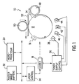
- a color electrophotography system 10 comprises a drum 12 that is coated, in the known manner, with a photoconductive surface 14. While a drum 12 is shown, those skilled in the art will realize that any continuous photoconductive surface 14 may be employed with this invention.
- An electrostatic charging station 16 charges photoconductive surface 14 as it passes therebeneath.
- a laser 18 subsequently exposes selected areas of pre-charged photoconductive surface 14 to create image areas that exhibit a different charge level.
- Electrophotographic system 10 is controlled by a microprocessor 30 which, in combination with image information in raster image buffer 32, feeds image data to laser 18 through laser control circuit 34.
- Microprocessor 30 also issues signals to operate toner supply control module 36 which in turn generates signals to control cyan, yellow, magenta, and black toner supplies 38, 40, 42, and 44, respectively.
- a toner conditioning roller 48 both compresses and heats toner applied to photoconductive surface 14.
- a transfer roller 50 provides both heat and pressure to a media sheet 52 thereby enabling toner transfer to occur from photoconductive surface 14 to media sheet 52.
- raster image buffers 22 contain at least three color planes, e.g., cyan, yellow and magenta.
- a color plane is read out and controls laser 18 to cause the particular color plane image to be produced on photoconductive surface 14.
- Toner supply control 36 then causes the appropriate toner module (e.g., cyan module 38), to operate and to develop the exposed cyan image on photoconductive surface 14. That image is then conditioned by roller 48 and proceeds around drum 12, past electrostatic charging station 16 where photoconductive surface 14 is again charged.
- a second color plane from raster image buffers 32 is then read out and controls laser 18 to discharge areas of photoconductive surface 14 that are to be developed using a second color toner.
- FIG. 2 A side view, best illustrating the preferred embodiment, is shown in FIG. 2.
- Housing 201 depicts a portion of the color electrophotographic system designed to receive the toner cartridges. Formed into housing 201 are four receptacles, one each for four different colored toner cartridges. Each receptacle includes a unique key hole that is designed to receive a corresponding key on a specific colored toner cartridge. Thus, by using the unique end-caps, toner cartridge 202 cannot accidentally be placed into the incorrect receptacle. See FIG. 3.
- FIG. 2 Another advantage of the housing of FIG. 2 is the ease of replacing a consumed cartridge.
- Most electrophotographic imaging systems require the user to open the device to gain access to the toner cartridge.
- the toner cartridges are designed to be aesthetically pleasing such that there is no need to hide the cartridges behind panels.
- the present invention may also be used behind cabinet doors should the designer so choose.
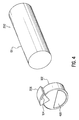
- FIG. 4 shows a single toner cartridge 202.
- Each toner cartridge is constructed from a common cartridge body 101 and a unique end-cap 102.
- the shape of the end-cap's key 206 indicates the color contained in the toner cartridge.
- a cartridge is designated a particular color by placing the appropriate end-cap on the cartridge body.
- manufacture cost are minimized by requiring manufacture of only one type of the more complicated body 101.
- cartridge body 101 may incorporate changes due to toner differences, the present invention does not preclude such unique designs to the body.
- indicator 104 Illumination of indicator 104 provides visual feedback to the user that toner cartridge 202 is properly seated in the housing 201. Additionally, indicator 104 might flash indicating that toner cartridge 202 is low or out of toner.
- indicator 104 is a colored lens that is illuminated by a light source from housing 201. By arranging it so, the disposable toner cartridge 202 does not need electrical contacts through which the indicator 104 is powered.
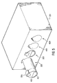
- Fig. 5 is a perspective view showing cartridge 202 partially inserted into housing 201.
- the endcap of cartridge 202 is formed to include key 206.
- Indentation 401 is formed in the endcap providing a convenient gripping area for the users fingers to extract toner cartridge 202 from housing 201.
- receptacles 403 and 404 are also visible in Fig. 5. These two receptacles are shown with their respective toner cartridges removed showing the respective key receptacle areas therein.
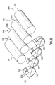
- Fig. 6 shows a perspective view of toner cartridges 202, 203, 204, 205.
- Each toner cartridge includes a common body 101-101C which is identical for all of the toner cartridges and a unique endcap 102, 207, 208, and 209. Focusing on one cartridge, the unique endcap 102 includes unique key 206. It is this unique key 206 which prohibits accidental insertion of one cartridge into another receptacle.
- Endcap 102 includes indentation 401 which provides easy access to the user to extract toner cartridge 202 from housing 201. Also shown in Fig. 6 is indicator 104.
- a color off-axis inkjet printers stores the ink in several non-movable reservoirs. As the ink in a reservoir is consumed, the reservoir must be replaced. Thus, by using the present invention, each reservoir is keyed and only a properly keyed reservoir may be inserted thereby insuring that the correct color ink in replaced.
Abstract
The present invention insures that the proper color toner (38, 40, 42, 44) used in a color printer (10) is replaced once the present supply is consumed The printer (10) has several of receptacles (403, 404), one receptacles for each colored toner (38, 40, 42, 44). Each receptacle has a unique key receptacle. The replacement toner (38, 40, 42, 44) comes in a cartridge (202, 203, 204, 205), one cartridge for each color of the several of colored toners (38, 40, 42, 43). A cartridge is constructed from a common body (101, 101A, 101B, 101C) to which an endcap (102) is attached. The endcap (102) has a unique key (206, 207, 208, 209) that mates with only one of the unique key receptacles. Each cartridge (202, 203, 204, 205) is removably inserted in the correct receptacle.
Description
- The present invention generally relates to cartridge replacement; and more specifically, to replacing toner cartridges in a multi-color electrophotographic printer.
- As known in the art of electrophotographic printer, a photographic surface in the electrophotographic printer is first charged to a uniform potential and then is "exposed" to an image to be reproduced by the scanning of a laser beam thereacross. The photoconductor thereby obtains and electrostatic latent image that constitutes a matrix of discharged pixels on the photoconductor's surface. In a black and white printer, the photoconductive surface is generally developed using a black toner that adheres to the discharged pixel areas to form the image. Thereafter, the toned photoconductive surface is then carried to a transfer station where the image is transferred to a media sheet.
- In a multi-color printer, successive images are developed employing different color toners supplied from corresponding toner modules. Color printing is normally done with yellow, cyan and magenta toner that are applied, in registration, during successive rotations of the photoconductive surface. The printer also generally include a toner module with black toner.
- As the toner in a cartridge, or reservoir, (herein referred to as a cartridge) is expended, the cartridge must be replaced. A toner cartridge must be replace with a new cartridge of the same color. This, like for like, replacement reduces chances for contaminating the new toner with old toner of a different color. An additional benefit from like for like replacements is reduced printer complexity because the printer does not need to sense the location of each color. However, like for like replacement requires that the user insert the proper color in the proper location.
- One approach is to color the toner cartridge to correspond to the toner color. This simple solution does not take into consideration the significant percentage of the population that is color blind. Another approach requires that the printer sense that the correct type toner cartridge has been inserted. One skilled in the art understands that this sensing requires additional hardware and firmware.
- The present invention insures that the proper color toner used in a color printer is replaced once the present supply is consumed The printer has several of receptacles, one receptacles for each colored toner. Each receptacle has a unique key receptacle. The replacement toner comes in a cartridge, one cartridge for each color of the several of colored toners. A cartridge is constructed from a common body to which an endcap is attached. The endcap has a unique key that mates with only one of the unique key receptacles. Each cartridge is removably inserted in the correct receptacle.
- A better understanding of the invention may be had from the consideration of the following detailed description taken in conjunction with the accompanying drawings in which:
- FIG. 1 is a block diagram of an electrophotographic imaging system.
- FIG. 2 shows four toner cartridges inserted into their correct receptacles in accordance with the present invention.
- FIG. 3 illustrates the result of attempting to insert a cartridge into the incorrect receptacle.
- FIG. 4 is a perspective view of a toner cartridge showing a common body and unique endcap.
- FIG. 5 shows a toner cartridges being inserted.
- FIG. 6 is a perspective view of all the toner cartridges showing the common bodies and unique endcaps.
- The present invention is not limited to a specific embodiment illustrated herein. Turning to Fig. 1, a
color electrophotography system 10 comprises a drum 12 that is coated, in the known manner, with aphotoconductive surface 14. While a drum 12 is shown, those skilled in the art will realize that any continuousphotoconductive surface 14 may be employed with this invention. Anelectrostatic charging station 16 chargesphotoconductive surface 14 as it passes therebeneath. Alaser 18 subsequently exposes selected areas of pre-chargedphotoconductive surface 14 to create image areas that exhibit a different charge level. -
Electrophotographic system 10 is controlled by amicroprocessor 30 which, in combination with image information inraster image buffer 32, feeds image data tolaser 18 throughlaser control circuit 34.Microprocessor 30 also issues signals to operate tonersupply control module 36 which in turn generates signals to control cyan, yellow, magenta, andblack toner supplies toner conditioning roller 48 both compresses and heats toner applied tophotoconductive surface 14. Atransfer roller 50 provides both heat and pressure to amedia sheet 52 thereby enabling toner transfer to occur fromphotoconductive surface 14 tomedia sheet 52. - In performing a color printing action, raster image buffers 22 contain at least three color planes, e.g., cyan, yellow and magenta. In synchronism with the rotation of drum 12, a color plane is read out and controls
laser 18 to cause the particular color plane image to be produced onphotoconductive surface 14.Toner supply control 36 then causes the appropriate toner module (e.g., cyan module 38), to operate and to develop the exposed cyan image onphotoconductive surface 14. That image is then conditioned byroller 48 and proceeds around drum 12, pastelectrostatic charging station 16 wherephotoconductive surface 14 is again charged. A second color plane fromraster image buffers 32 is then read out and controlslaser 18 to discharge areas ofphotoconductive surface 14 that are to be developed using a second color toner. (At this point, it is to be noted that there is no media sheet present in contact with drum 12 and such contact will not occur until all color planes have been read out to controllaser 18 to produce registered images.) The exposure/development actions proceed through the cyan, yellow, magenta and black toner stations, in sequence, untilphotoconductive surface 14 has been toned in accordance with the image information contained in allraster image buffers 32. - From the above simplified description of the operation of a color electrophotographic printer, it should be clear that
microprocessor 30 must know the proper location of the individual colors to properly render a color image. The preferred embodiment of the present invention uses a unique keying system to insure that a toner cartridge can only be inserted in its designated receptacle. A side view, best illustrating the preferred embodiment, is shown in FIG. 2.Housing 201 depicts a portion of the color electrophotographic system designed to receive the toner cartridges. Formed intohousing 201 are four receptacles, one each for four different colored toner cartridges. Each receptacle includes a unique key hole that is designed to receive a corresponding key on a specific colored toner cartridge. Thus, by using the unique end-caps,toner cartridge 202 cannot accidentally be placed into the incorrect receptacle. See FIG. 3. - Another advantage of the housing of FIG. 2 is the ease of replacing a consumed cartridge. Most electrophotographic imaging systems require the user to open the device to gain access to the toner cartridge. By using the preferred embodiment of the present invention, the toner cartridges are designed to be aesthetically pleasing such that there is no need to hide the cartridges behind panels. However, the present invention may also be used behind cabinet doors should the designer so choose.
- FIG. 4 shows a
single toner cartridge 202. Each toner cartridge is constructed from acommon cartridge body 101 and a unique end-cap 102. The shape of the end-cap's key 206 indicates the color contained in the toner cartridge. A cartridge is designated a particular color by placing the appropriate end-cap on the cartridge body. Thus, manufacture cost are minimized by requiring manufacture of only one type of the morecomplicated body 101. One skilled in the art will understand thatcartridge body 101 may incorporate changes due to toner differences, the present invention does not preclude such unique designs to the body. - Also shown in FIG. 4 is
indicator 104. Illumination ofindicator 104 provides visual feedback to the user thattoner cartridge 202 is properly seated in thehousing 201. Additionally,indicator 104 might flash indicating thattoner cartridge 202 is low or out of toner. One skilled in the art can devise other uses and meanings for the indicator. The present invention is not meant to be limited to those functions described here. In the preferred embodiment,indicator 104 is a colored lens that is illuminated by a light source fromhousing 201. By arranging it so, thedisposable toner cartridge 202 does not need electrical contacts through which theindicator 104 is powered. - Fig. 5 is a perspective
view showing cartridge 202 partially inserted intohousing 201. As described earlier, the endcap ofcartridge 202 is formed to include key 206.Indentation 401 is formed in the endcap providing a convenient gripping area for the users fingers to extracttoner cartridge 202 fromhousing 201. Also visible in Fig. 5 arereceptacles - Fig. 6 shows a perspective view of
toner cartridges unique endcap unique endcap 102 includesunique key 206. It is this unique key 206 which prohibits accidental insertion of one cartridge into another receptacle.Endcap 102 includesindentation 401 which provides easy access to the user to extracttoner cartridge 202 fromhousing 201. Also shown in Fig. 6 isindicator 104. - Although the preferred embodiment of the invention has been illustrated, and that form described, it is readily apparent to those skilled in the art that various modifications may be made therein without departing from the spirit of the invention or from the scope of the appended claims.
- While the preferred embodiment has been described in conjunction with an electrophotographic printer, the present invention is equally applicable to other type of printing methods. For example, a color off-axis inkjet printers stores the ink in several non-movable reservoirs. As the ink in a reservoir is consumed, the reservoir must be replaced. Thus, by using the present invention, each reservoir is keyed and only a properly keyed reservoir may be inserted thereby insuring that the correct color ink in replaced.
Claims (10)
- A printing apparatus (10) using a plurality of consumables (38, 40, 42, 44), said apparatus comprising:a plurality of cylindrical shaped receptacles (403, 404), one receptacle for each of said plurality of consumables (38, 40, 42, 44), each receptacle having a unique key receptacle; anda plurality of cartridges (202, 203, 204, 205), one cartridge for each of said plurality of consumables (38, 40, 42, 44), each cartridge removably insertable in one of said plurality of receptacles (403, 404), each cartridge of said plurality of cartridges comprising:a body (101, 101A, 101B, 101C) having a cylindrical cross section of a first radius, said body having a closed first end and a second end; andan endcap (102) attached to said second end of said body (101, 101A, 101B, 101C), said endcap having a unique key (206) extending to a second radius where said second radius is greater than said first radius, said unique key (208) mates with one of said unique key receptacles.
- The printing apparatus (10) of claim 1 wherein said cartridge (202, 203, 204, 205) further comprising a cavity bounded by said body (101, 101A, 101B, 101C) and said endcap (102, 207, 208, 209), said consumable (38, 40, 42, 44) being contained in said cavity.
- A printing apparatus (10) using a plurality of colored toners (38, 40, 42, 44), said apparatus comprising:a plurality of receptacles (403, 404), one receptacle for each color of said plurality of colored toners (38, 40, 42, 44), each receptacle (403, 404) having a unique key receptacle; anda plurality of cartridges (202, 203, 204, 205), one cartridge for each color of said plurality of colored toners (38, 40, 42, 44), each cartridge removably insertable in one of said plurality of receptacles, each cartridge of said plurality of cartridges (202, 203, 204, 205) comprising:a body (101, 101A, 101B, 101C) having a first end and a second end; andan endcap (102) attached to said second end of said body (101, 101A, 101B, 101C), said endcap (102) having a unique key (206) that mates with one of said unique key receptacles.
- The printing apparatus (10) of claim 3 wherein said first end of said body (101, 101A, 101B, 101C) being closed forming a cavity inside said body.
- The printing apparatus (10) of claim 3 wherein:said endcap (102) having a cylindrical cross section of a radius, said unique key (206) extending to a radius greater than said radius of said cylindrical cross section.
- A printer comprising:marking means (10) for placing a mark onto a media (52);a first toner (38);a second toner (44);a first receptacle (403) having a first key receptacle;a second (404) having a second key receptacle;a first cartridge (204) removably inserted in said first receptacle (403), said first cartridge (204) contains said first toner (38), said first cartridge (204) comprising:a first body (101B) having a cylindrical cross section of a first radius, said first body (101B) having a closed first end and a second end;a first endcap (208) attached to said second end of said first body (101B), said first endcap (208) having a first key (208) extending to a second radius where said second radius is greater than said first radius, said first key (208) mates with said first key receptacle;a second cartridge (205) removably inserted in said second receptacle (404), said second cartridge (205) contains said second toner (40), said second cartridge (205) comprising:a second body (101C) having a cylindrical cross section of a third radius, said second body (101C) having a closed first end and a second end; anda second endcap (209) attached to said second end of said second body (101C), said second endcap (209) having a second key (209) extending to a fourth radius where said fourth radius is greater than said second radius, said second key (209) mates with said second key receptacle.
- The printer claimed in claim 6 wherein said marking means (10) is an electrophotographic printer.
- The printer claimed in claim 6 wherein said marking means (10) is an injet printer.
- The printer claimed in claim 6 wherein said first cartridge (204) further comprising a first cavity that contains said first toner (38), said first cavity bounded by first body (101B) and first endcap (208).
- The printer claimed in claim 6 wherein said second cartridge (205) further comprising a second cavity that contains said second toner (40), said second cavity bounded by second body (101) and second endcap (209).
Applications Claiming Priority (2)
| Application Number | Priority Date | Filing Date | Title |
|---|---|---|---|
| US404793 | 1989-09-08 | ||
| US08/404,793 US5530531A (en) | 1995-03-15 | 1995-03-15 | Multiple cartridge keying apparatus |
Publications (1)
| Publication Number | Publication Date |
|---|---|
| EP0732632A1 true EP0732632A1 (en) | 1996-09-18 |
Family
ID=23601064
Family Applications (1)
| Application Number | Title | Priority Date | Filing Date |
|---|---|---|---|
| EP95118638A Withdrawn EP0732632A1 (en) | 1995-03-15 | 1995-11-27 | Multiple cartridge keying apparatus |
Country Status (3)
| Country | Link |
|---|---|
| US (1) | US5530531A (en) |
| EP (1) | EP0732632A1 (en) |
| JP (1) | JPH08272277A (en) |
Cited By (1)
| Publication number | Priority date | Publication date | Assignee | Title |
|---|---|---|---|---|
| EP1839880A2 (en) * | 2003-07-31 | 2007-10-03 | Hewlett-Packard Development Company L.P. | Printing-fluid container |
Families Citing this family (63)
| Publication number | Priority date | Publication date | Assignee | Title |
|---|---|---|---|---|
| US6183077B1 (en) * | 1995-04-27 | 2001-02-06 | Hewlett-Packard Company | Method and apparatus for keying ink supply containers |
| US6017118A (en) * | 1995-04-27 | 2000-01-25 | Hewlett-Packard Company | High performance ink container with efficient construction |
| JPH0939265A (en) * | 1995-07-29 | 1997-02-10 | Seiko Epson Corp | Ink cartridge for printer and identifying device therefor |
| US6097405A (en) * | 1996-09-30 | 2000-08-01 | Hewlett-Packard Company | Detection apparatus and method for use in a printing device |
| DE69804148T2 (en) * | 1997-05-16 | 2003-01-09 | Hewlett Packard Co | Mechanical and electrical coding device for replaceable ink cartridge |
| JPH1124530A (en) * | 1997-07-04 | 1999-01-29 | Oki Data:Kk | Image forming device |
| KR100243233B1 (en) * | 1997-07-31 | 2000-02-01 | 윤종용 | Toner cartridge for a image forming apparatus |
| KR100307584B1 (en) * | 1998-02-27 | 2001-12-12 | 윤종용 | Apparatus for supplying ink for liquid electrographic printer |
| US6619766B1 (en) * | 1999-10-12 | 2003-09-16 | Gateway, Inc. | Device mounting and retention assembly |
| US6561413B2 (en) * | 2001-02-27 | 2003-05-13 | Fuji Hunt Photographic Chemicals, Inc. | Corrugated container and method of making same |
| US6554402B2 (en) | 2001-08-16 | 2003-04-29 | Eastman Kodak Company | Ink cartridge with color discrimination structure |
| US6600881B2 (en) * | 2001-10-20 | 2003-07-29 | Hewlett-Packard Development Company, Lp. | Methods and apparatus for facilitating installation of imaging media cartridges in imaging apparatus |
| US6505006B1 (en) * | 2001-11-15 | 2003-01-07 | Xerox Corporation | Supply cartridge for a printing apparatus |
| JP4329297B2 (en) * | 2002-03-01 | 2009-09-09 | コニカミノルタビジネステクノロジーズ株式会社 | Color image forming apparatus |
| US20040012660A1 (en) * | 2002-07-18 | 2004-01-22 | Eastman Kodak Company | Ink cartridge having connectable-disconnectable housing and ink supply bag |
| US6715864B2 (en) | 2002-07-18 | 2004-04-06 | Eastman Kodak Company | Disposable ink supply bag having connector-fitting |
| US6712459B2 (en) | 2002-07-18 | 2004-03-30 | Eastman Kodak Company | Ink cartridge having shielded pocket for memory chip |
| US6705713B2 (en) | 2002-07-18 | 2004-03-16 | Eastman Kodak Company | Disposable ink assemblage |
| US6702435B2 (en) * | 2002-07-18 | 2004-03-09 | Eastman Kodak Company | Ink cartridge having ink identifier oriented to provide ink identification |
| US6709093B2 (en) | 2002-08-08 | 2004-03-23 | Eastman Kodak Company | Ink cartridge in which ink supply bag held fast to housing |
| US6755501B2 (en) | 2002-08-08 | 2004-06-29 | Eastman Kodak Company | Alternative ink/cleaner cartridge |
| US6830323B2 (en) | 2002-08-13 | 2004-12-14 | Eastman Kodak Company | Restricting flash spread when welding housing halves of cartridge together |
| US6705714B1 (en) | 2002-08-21 | 2004-03-16 | Eastman Kodak Company | Ink cartridge having ink supply bag filled to less than capacity and folded in cartridge housing |
| US6837576B2 (en) | 2002-08-21 | 2005-01-04 | Eastman Kodak Company | Method of filling ink supply bag for ink cartridge |
| JP4133154B2 (en) * | 2002-09-19 | 2008-08-13 | 株式会社リコー | Ink cartridge and inkjet printer |
| US6749294B2 (en) * | 2002-10-10 | 2004-06-15 | Hewlett-Packard Development Company, L.P. | Keying methods and apparatus for inkjet print cartridges and inkjet printers |
| JP2005111976A (en) * | 2003-09-18 | 2005-04-28 | Ricoh Co Ltd | Consumables, parts mounting structure and image forming device |
| JP4488718B2 (en) * | 2003-11-19 | 2010-06-23 | 株式会社リコー | Electronic device, electronic device replacement part, replacement part package, and identification unit arrangement method |
| JP4483349B2 (en) * | 2004-03-08 | 2010-06-16 | 富士ゼロックス株式会社 | cartridge |
| JP2006027218A (en) * | 2004-07-21 | 2006-02-02 | Brother Ind Ltd | Consumable member of image forming device, and image forming device which consumable member is attached to and detached from |
| JP4456957B2 (en) * | 2004-08-06 | 2010-04-28 | 株式会社リコー | Toner cartridge and image forming apparatus |
| US20060164465A1 (en) * | 2005-01-21 | 2006-07-27 | Steinmetz Charles R | Receptacle for colored marking material container |
| US7766900B2 (en) | 2005-02-21 | 2010-08-03 | Biomet Manufacturing Corp. | Method and apparatus for application of a fluid |
| US20060204249A1 (en) * | 2005-03-10 | 2006-09-14 | Kabushiki Kaisha Toshiba | Toner cartridge and image forming apparatus |
| JP4696613B2 (en) * | 2005-03-16 | 2011-06-08 | ブラザー工業株式会社 | ink cartridge |
| TWI534562B (en) | 2005-04-27 | 2016-05-21 | Ricoh Co Ltd | Toner container and image forming device |
| EP1890201B1 (en) * | 2005-06-07 | 2014-12-31 | Ricoh Company, Ltd. | Toner container and image forming device |
| JP4189690B2 (en) * | 2006-04-12 | 2008-12-03 | セイコーエプソン株式会社 | Liquid container |
| DE102006036716B3 (en) * | 2006-06-02 | 2007-09-27 | Artech Gmbh Design + Production In Plastic | Printer e.g. inkjet printer, retrofitting device, has cartridge retaining device to retain replaceable original ink cartridges, and locking pin to lock fastener in fastening position when insert-ink cartridge is attached in retaining device |
| US20080018717A1 (en) * | 2006-07-21 | 2008-01-24 | Hewlett-Packard Development Company Lp | Transfer station |
| US8050597B2 (en) * | 2006-11-09 | 2011-11-01 | Ricoh Company, Limited | Toner container having a gear portion and image forming apparatus |
| US8182769B2 (en) | 2008-04-04 | 2012-05-22 | Biomet Biologics, Llc | Clean transportation system |
| US8518272B2 (en) | 2008-04-04 | 2013-08-27 | Biomet Biologics, Llc | Sterile blood separating system |
| US8388695B2 (en) * | 2008-07-01 | 2013-03-05 | Whirlpool Corporation | Apparatus and method for controlling laundering cycle by sensing wash aid concentration |
| US8266748B2 (en) * | 2008-07-01 | 2012-09-18 | Whirlpool Corporation | Apparatus and method for controlling bulk dispensing of wash aid by sensing wash aid concentration |
| US8397328B2 (en) * | 2008-07-01 | 2013-03-19 | Whirlpool Corporation | Apparatus and method for controlling concentration of wash aid in wash liquid |
| US9480789B2 (en) | 2009-06-01 | 2016-11-01 | Ethicon Endo-Surgery, Inc. | Method and sedation delivery system including a pump assembly and a co-formulation of first and second drugs |
| US9242042B2 (en) * | 2009-07-21 | 2016-01-26 | Ethicon Endo-Surgery, Inc. | Drug delivery system including a drug-container holder and a pump assembly |
| EP2480266B1 (en) * | 2009-09-21 | 2018-05-30 | Novo Nordisk A/S | Drug delivery system and device with cap function |
| EP2378374B1 (en) | 2010-04-01 | 2019-09-25 | Ricoh Company, Ltd. | Powder container, powder supply assembly, and image forming apparatus |
| JP2012103427A (en) * | 2010-11-09 | 2012-05-31 | Ricoh Co Ltd | Image forming apparatus |
| JP2013174652A (en) * | 2012-02-23 | 2013-09-05 | Canon Inc | Cartridge |
| US20150063872A1 (en) * | 2013-09-02 | 2015-03-05 | Samsung Electronics Co., Ltd. | Image forming apparatus |
| US9335723B2 (en) | 2013-09-02 | 2016-05-10 | Samsung Electronics Co., Ltd. | Image forming apparatus and container mounting groove thereof |
| CN107107093A (en) * | 2014-09-23 | 2017-08-29 | Sika技术股份公司 | Ceiling device, storage container device, wound packages are put, distributing equipment and their purposes |
| JP6460002B2 (en) * | 2016-02-15 | 2019-01-30 | 京セラドキュメントソリューションズ株式会社 | Image forming apparatus |
| JP6546559B2 (en) * | 2016-03-31 | 2019-07-17 | 株式会社沖データ | Development processing apparatus, development apparatus and image forming apparatus |
| JP6597559B2 (en) * | 2016-10-31 | 2019-10-30 | 京セラドキュメントソリューションズ株式会社 | Toner container and image forming apparatus provided with toner container |
| JP6737231B2 (en) * | 2017-05-15 | 2020-08-05 | 京セラドキュメントソリューションズ株式会社 | Toner container, image forming apparatus including the same, and toner container set |
| US10899135B2 (en) * | 2017-11-09 | 2021-01-26 | Entrust Corporation | Drop-on-demand printer with bottle ink supply and keyed bottle cap |
| JP7081175B2 (en) * | 2018-01-26 | 2022-06-07 | 京セラドキュメントソリューションズ株式会社 | Mounting unit |
| JP7183777B2 (en) * | 2018-12-25 | 2022-12-06 | ブラザー工業株式会社 | liquid supply system |
| DE102020114307B4 (en) | 2020-05-28 | 2024-04-04 | General Plastic Industrial Co., Ltd. | FAIL-PROOF DEVICE FOR A TONER CARTRIDGE AND TONER CARTRIDGE USING THE SAME |
Citations (6)
| Publication number | Priority date | Publication date | Assignee | Title |
|---|---|---|---|---|
| JPS60207167A (en) * | 1984-03-31 | 1985-10-18 | Casio Comput Co Ltd | Image forming device |
| JPS6135468A (en) * | 1984-07-27 | 1986-02-19 | Hitachi Metals Ltd | Toner supply device |
| US4611899A (en) * | 1983-01-08 | 1986-09-16 | Canon Kabushiki Kaisha | Developing apparatus |
| JPH01255874A (en) | 1988-04-06 | 1989-10-12 | Hitachi Metals Ltd | Toner supplying device |
| US4907019A (en) * | 1989-03-27 | 1990-03-06 | Tektronix, Inc. | Ink jet cartridges and ink cartridge mounting system |
| EP0667564A2 (en) * | 1994-02-15 | 1995-08-16 | Hewlett-Packard Company | Electrophotographic imaging with toners of opposite sign electrical charge |
Family Cites Families (4)
| Publication number | Priority date | Publication date | Assignee | Title |
|---|---|---|---|---|
| JPS6125168A (en) * | 1984-07-13 | 1986-02-04 | Nec Corp | Toner cartridge |
| JPS6128979A (en) * | 1984-07-20 | 1986-02-08 | Nec Corp | Toner cartridge |
| JPS61162071A (en) * | 1985-01-11 | 1986-07-22 | Konishiroku Photo Ind Co Ltd | Color copying machine |
| AU1812392A (en) * | 1991-07-12 | 1993-01-14 | Minnesota Mining And Manufacturing Company | Bottle keying system |
-
1995
- 1995-03-15 US US08/404,793 patent/US5530531A/en not_active Expired - Lifetime
- 1995-11-27 EP EP95118638A patent/EP0732632A1/en not_active Withdrawn
-
1996
- 1996-03-14 JP JP8057104A patent/JPH08272277A/en active Pending
Patent Citations (6)
| Publication number | Priority date | Publication date | Assignee | Title |
|---|---|---|---|---|
| US4611899A (en) * | 1983-01-08 | 1986-09-16 | Canon Kabushiki Kaisha | Developing apparatus |
| JPS60207167A (en) * | 1984-03-31 | 1985-10-18 | Casio Comput Co Ltd | Image forming device |
| JPS6135468A (en) * | 1984-07-27 | 1986-02-19 | Hitachi Metals Ltd | Toner supply device |
| JPH01255874A (en) | 1988-04-06 | 1989-10-12 | Hitachi Metals Ltd | Toner supplying device |
| US4907019A (en) * | 1989-03-27 | 1990-03-06 | Tektronix, Inc. | Ink jet cartridges and ink cartridge mounting system |
| EP0667564A2 (en) * | 1994-02-15 | 1995-08-16 | Hewlett-Packard Company | Electrophotographic imaging with toners of opposite sign electrical charge |
Non-Patent Citations (2)
| Title |
|---|
| PATENT ABSTRACTS OF JAPAN vol. 010, no. 068 (P - 437) 18 March 1986 (1986-03-18) * |
| PATENT ABSTRACTS OF JAPAN vol. 010, no. 190 (P - 474) 4 July 1986 (1986-07-04) * |
Cited By (7)
| Publication number | Priority date | Publication date | Assignee | Title |
|---|---|---|---|---|
| EP1839880A2 (en) * | 2003-07-31 | 2007-10-03 | Hewlett-Packard Development Company L.P. | Printing-fluid container |
| EP1839880A3 (en) * | 2003-07-31 | 2007-11-14 | Hewlett-Packard Development Company L.P. | Printing-fluid container |
| EP2028013A1 (en) * | 2003-07-31 | 2009-02-25 | Hewlett-Packard Development Company, L.P. | Printing-fluid container |
| US7506973B2 (en) | 2003-07-31 | 2009-03-24 | Hewlett-Packard Development Company, L.P. | Printing-fluid container |
| EP2168772A3 (en) * | 2003-07-31 | 2010-08-18 | Hewlett-Packard Development Company, L.P. | Printing System |
| EP2258554A1 (en) * | 2003-07-31 | 2010-12-08 | Hewlett-Packard Development Company, L.P. | Printing system |
| EP2902207A3 (en) * | 2003-07-31 | 2017-05-10 | Hewlett-Packard Development Company, L.P. | Printing Fluid Container |
Also Published As
| Publication number | Publication date |
|---|---|
| US5530531A (en) | 1996-06-25 |
| JPH08272277A (en) | 1996-10-18 |
Similar Documents
| Publication | Publication Date | Title |
|---|---|---|
| US5530531A (en) | Multiple cartridge keying apparatus | |
| EP0791863B1 (en) | A method for calibrating a spatial light modulator printing system | |
| US5963759A (en) | Process cartridge and image forming apparatus to which process cartridge can detachably be mounted | |
| US6895191B2 (en) | Insertion verification of replaceable module of printing apparatus | |
| EP1055979B1 (en) | Image forming apparatus and process unit mountable to image forming apparatus | |
| US6498905B1 (en) | Image forming cartridge set-up and control | |
| EP0513825B1 (en) | Image forming system and process cartridge mountable on same | |
| US6366747B1 (en) | Customizable control panel for a functionally upgradable image printing machine | |
| EP0851312A3 (en) | Color-image forming apparatus for printing a color image | |
| EP0893909A2 (en) | Image forming device | |
| JPH10198236A (en) | Color image forming device | |
| US20030123887A1 (en) | Adertising from the customer replaceable unit memory of a copier or printer cartridge | |
| US10996587B2 (en) | Image forming apparatus with a plurality of developer container each having an engagement portion | |
| GB2233605A (en) | Electrostatographic typewriters. | |
| CN101201572A (en) | Image forming apparatus and control method thereof | |
| CN100378602C (en) | Process cartridge and electrophotographic image forming apparatus | |
| US5450189A (en) | Electrophotographic imaging with toners of opposite sign electrical charge | |
| CN102713766A (en) | Multicolor electrophotographic print engine | |
| EP1207438B1 (en) | System and method for providing a simplified upgrade path for an image forming apparatus using a removable cartridge | |
| EP1319994A3 (en) | Electrophotographic development system | |
| KR100247975B1 (en) | Electrographic printer | |
| US20050019062A1 (en) | Color electrophotographic printer | |
| JPH0429165A (en) | Image forming device | |
| US6889025B2 (en) | Color image forming apparatus having developers in a fixed position with respect to a photosensitive medium | |
| CN100485550C (en) | Image forming apparatus and image forming system |
Legal Events
| Date | Code | Title | Description |
|---|---|---|---|
| PUAI | Public reference made under article 153(3) epc to a published international application that has entered the european phase |
Free format text: ORIGINAL CODE: 0009012 |
|
| 17P | Request for examination filed |
Effective date: 19960523 |
|
| AK | Designated contracting states |
Kind code of ref document: A1 Designated state(s): DE FR GB IT |
|
| 17Q | First examination report despatched |
Effective date: 19981009 |
|
| STAA | Information on the status of an ep patent application or granted ep patent |
Free format text: STATUS: THE APPLICATION HAS BEEN WITHDRAWN |
|
| 18W | Application withdrawn |
Withdrawal date: 19990512 |