EP0706781A2 - Morcellator - Google Patents
Morcellator Download PDFInfo
- Publication number
- EP0706781A2 EP0706781A2 EP95115807A EP95115807A EP0706781A2 EP 0706781 A2 EP0706781 A2 EP 0706781A2 EP 95115807 A EP95115807 A EP 95115807A EP 95115807 A EP95115807 A EP 95115807A EP 0706781 A2 EP0706781 A2 EP 0706781A2
- Authority
- EP
- European Patent Office
- Prior art keywords
- recited
- surgical apparatus
- tissue
- cutting member
- surgical
- Prior art date
- Legal status (The legal status is an assumption and is not a legal conclusion. Google has not performed a legal analysis and makes no representation as to the accuracy of the status listed.)
- Granted
Links
Images


Classifications
-
- A—HUMAN NECESSITIES
- A61—MEDICAL OR VETERINARY SCIENCE; HYGIENE
- A61B—DIAGNOSIS; SURGERY; IDENTIFICATION
- A61B17/00—Surgical instruments, devices or methods, e.g. tourniquets
- A61B17/32—Surgical cutting instruments
- A61B17/320016—Endoscopic cutting instruments, e.g. arthroscopes, resectoscopes
-
- A—HUMAN NECESSITIES
- A61—MEDICAL OR VETERINARY SCIENCE; HYGIENE
- A61B—DIAGNOSIS; SURGERY; IDENTIFICATION
- A61B17/00—Surgical instruments, devices or methods, e.g. tourniquets
- A61B17/00234—Surgical instruments, devices or methods, e.g. tourniquets for minimally invasive surgery
-
- A—HUMAN NECESSITIES
- A61—MEDICAL OR VETERINARY SCIENCE; HYGIENE
- A61B—DIAGNOSIS; SURGERY; IDENTIFICATION
- A61B17/00—Surgical instruments, devices or methods, e.g. tourniquets
- A61B17/28—Surgical forceps
- A61B17/29—Forceps for use in minimally invasive surgery
-
- A—HUMAN NECESSITIES
- A61—MEDICAL OR VETERINARY SCIENCE; HYGIENE
- A61B—DIAGNOSIS; SURGERY; IDENTIFICATION
- A61B17/00—Surgical instruments, devices or methods, e.g. tourniquets
- A61B17/28—Surgical forceps
- A61B17/29—Forceps for use in minimally invasive surgery
- A61B17/295—Forceps for use in minimally invasive surgery combined with cutting implements
-
- A—HUMAN NECESSITIES
- A61—MEDICAL OR VETERINARY SCIENCE; HYGIENE
- A61B—DIAGNOSIS; SURGERY; IDENTIFICATION
- A61B17/00—Surgical instruments, devices or methods, e.g. tourniquets
- A61B17/32—Surgical cutting instruments
- A61B17/320016—Endoscopic cutting instruments, e.g. arthroscopes, resectoscopes
- A61B17/32002—Endoscopic cutting instruments, e.g. arthroscopes, resectoscopes with continuously rotating, oscillating or reciprocating cutting instruments
-
- A—HUMAN NECESSITIES
- A61—MEDICAL OR VETERINARY SCIENCE; HYGIENE
- A61B—DIAGNOSIS; SURGERY; IDENTIFICATION
- A61B17/00—Surgical instruments, devices or methods, e.g. tourniquets
- A61B17/00234—Surgical instruments, devices or methods, e.g. tourniquets for minimally invasive surgery
- A61B2017/00353—Surgical instruments, devices or methods, e.g. tourniquets for minimally invasive surgery one mechanical instrument performing multiple functions, e.g. cutting and grasping
-
- A—HUMAN NECESSITIES
- A61—MEDICAL OR VETERINARY SCIENCE; HYGIENE
- A61B—DIAGNOSIS; SURGERY; IDENTIFICATION
- A61B17/00—Surgical instruments, devices or methods, e.g. tourniquets
- A61B17/32—Surgical cutting instruments
- A61B17/3205—Excision instruments
- A61B17/3207—Atherectomy devices working by cutting or abrading; Similar devices specially adapted for non-vascular obstructions
- A61B17/320758—Atherectomy devices working by cutting or abrading; Similar devices specially adapted for non-vascular obstructions with a rotating cutting instrument, e.g. motor driven
- A61B2017/320775—Morcellators, impeller or propeller like means
-
- A—HUMAN NECESSITIES
- A61—MEDICAL OR VETERINARY SCIENCE; HYGIENE
- A61B—DIAGNOSIS; SURGERY; IDENTIFICATION
- A61B17/00—Surgical instruments, devices or methods, e.g. tourniquets
- A61B17/34—Trocars; Puncturing needles
- A61B17/3417—Details of tips or shafts, e.g. grooves, expandable, bendable; Multiple coaxial sliding cannulas, e.g. for dilating
- A61B17/3421—Cannulas
- A61B2017/3445—Cannulas used as instrument channel for multiple instruments
Definitions
- the subject application relates to a surgical apparatus for fragmenting and removing tissue or bodily organ parts during surgery, and is particularly adapted to use during endoscopic surgical procedures.
- endoscopic surgery involves incising through body walls for examining, viewing and/or operating on various bodily organs or structures, including the ovaries, uterus, gall bladder, bowels, kidneys, appendix, etc.
- a trocar typically creates an incision and trocar tubes or cannula devices are extended into and left in place in the abdominal wall so that endoscopic surgical tools may be inserted through the trocar cannula.
- a camera or endoscope is inserted through the trocar cannula which, is generally located at the navel incision, thereby enabling the visual inspection and magnification of a cavity in the body.
- the surgeon then performs the desired procedure at the surgical site with the aid of specialized instrumentation designed to fit through additional trocar cannulas which provide additional entries into the desired body cavity.
- endoscopic surgery results in several smaller incisions, usually between 5 and 15 millimeters in size. In most instances, recovery is quicker and less painful than traditional surgery.
- surgeons are often better able to dissect blood vessels and control blood loss.
- heat and water loss are often reduced as a result of the smaller incisions.
- tissue or diseased organs In many surgical procedures, it is often necessary to remove tissue or diseased organs. This is especially challenging during endoscopic surgery because the tissue or organ removal must be achieved through the small openings through which the procedure is performed. In these situations it may be desirable to fragment, or morcellate, or cut into smaller segments the bodily tissue so that it can be readily removed through the small endoscopic openings.
- Morcellation involves fragmenting and removing diseased tissue or organ parts from healthy tissue or organs.
- the fragmented pieces are typically removed from the patient's body through a small incision or through a trocar cannula device which extends through the abdominal wall.
- tissue or organ part is diseased or infected, it is preferred that the excised portions thereof be isolated from contact with surrounding healthy tissue. Accordingly, it is often necessary to enclose the fragmented organ during removal, thus preventing contamination of healthy tissue and bodily organs.
- a device for accomplishing such a task is disclosed in U.S. Patent No. 4,428,375 which describes a drawstring bag for encapsulating a fragmented organ during surgical repair.
- the organ is fragmented in the bag by a surgical device known as a morcellator, until such a time as the entire specimen is small enough to be removed while in the bag, from the abdominal cavity, via the trocar cannula.
- the fragmented tissue pieces must be of a suitable size and shape.
- Manually operated morcellators are typically operated by a hand lever connected to an elongated endoscopic member. The distal end of the endoscopic member is connected to cutting members which are operatively associated through the endoscopic member with the hand lever.
- the manually operated morcellator is advanced to the surgical site where the tissue or bodily organ part to be separated is positioned between the cutting members. The surgeon then actuates the cutting members to cut the tissue or organ part.
- the surgeon must repeatedly remove the morcellator completely from the abdominal cavity to remove the fragmented tissue or bodily organ part from the cutting member and then reinsert the morcellator, via the trocar cannula, back to the surgical site to remove a further tissue or organ part. If the removed tissue or organ is diseased or infected, it may be necessary to place the organ in a surgical bag prior to fragmentation and removal. When the surgical bag is employed, the cutting edges of the morcellator cannot cut the surgical bag because such would result in tearing the bag and potentially exposing diseased tissue to healthy body tissue.
- Electric morcellators are generally used in conjunction with a surgical bag and are typically provided with a high speed cutting blade that rapidly fragments the tissue or organ into very small pieces within the bag to enhance removability. The fragmented tissue or organ can then be aspirated from the bag, or the entire bag may be removed containing the fragmented tissue.
- One such electric morcellator is described in U.S. Patent 5,215,521 to Cochran et al.
- Such electric morcellators may disadvantageously result in the rotating cutting blade cutting the surgical bag, thus risking the possibility that healthy tissue surrounding the surgical bag may become contaminated by the resulting leakage. Additionally, the tissue or organ parts which are fragmented by the electric morcellator may be insufficiently sized to undergo a proper pathologic evaluation.
- an endoscopic morcellator which is easy to operate, capable of aiding in the removal of diseased tissue without infecting surrounding healthy tissue, and which fragments tissue in manner which allows the pieces to be of a sufficient size to undergo a proper pathologic evaluation.
- endoscopic procedures are more common than laparoscopic procedures
- the present application utilizes terms of endoscopic procedures and apparatus.
- use herein of terms such as “endoscopic”, “endoscopically”, and “endoscopic portion”, among others, should not be construed as limited to an apparatus for use only in conjunction with an endoscopic tube. To the contrary, it is believed that the apparatus described herein may find use in other procedures wherein access is limited to a small incision, such as, for example laparoscopic or arthroscopic procedures.
- the present application is directed to a surgical apparatus having a pair of cooperating jaw members and a cutting member for cutting and removing tissue or organ parts during an endoscopic procedure.
- the apparatus includes a handle assembly, an elongated body portion extending from the handle assembly and defining a longitudinal axis, and a tool assembly associated with a distal end portion of the elongated body portion.
- the tool assembly includes the pair of cooperating jaw members and the cutting member. More particularly, the cutting member is positioned within an internal cavity being defined by the cooperating jaw members.
- the surgical apparatus further includes a first actuation mechanism for remotely actuating the cooperating jaw members between a closed position substantially parallel to the longitudinal axis of the elongated body portion and an open position, such that at least one jaw member is disposed angularly with respect to the longitudinal axis of the elongated body portion in the open position.
- a second actuation mechanism is also provided for actuating the cutting member relative to the cooperating jaw members.
- the second actuation mechanism for actuating the cutting member includes a handle member and actuation arms which interconnect the cutting member to the handle member which is operatively associated with the handle assembly.
- the reciprocal movement of the cutting member is preferably achieved through movement of the handle member which causes the actuation arms to translate reciprocatingly with respect to a transverse axis of the body portion.
- the first actuation mechanism for effectuating the remote actuation of the cooperating jaw members preferably includes a trigger member and at least one linkage member which interconnects at least one of the cooperating jaw members to the trigger member which is operatively associated with the handle assembly. Jaw actuation is achieved by causing reciprocating longitudinal movement of the linkage members through manipulation of the trigger portion.
- the elongated body portion of the surgical apparatus is provided with a bore extending therethrough which is configured to enable a surgical instrument to pass through the bore defined in the elongated portion.
- the bore should also have a suitable diameter so as to allow the passage of tissue samples therethrough.
- the surgical instrument is configured to extend through the bore of the elongated body portion and preferably includes an elongated member having opposing distal and proximal ends .
- the distal end of the elongated member of the surgical instrument includes a tool assembly preferably configured and adapted to engage and/or grasp tissue.
- the proximal end preferably includes a handle mechanism to effectuate actuation of the tool assembly to engage and/or grasp the tissue.
- the surgical apparatus described herein is particularly adapted for use during endoscopic surgical techniques. However, it is to be appreciated that the surgical apparatus can be used during any operative procedure requiring the fragmentation and removal of tissue or organ parts. Further features of the surgical apparatus described herein will become more readily apparent from the following detailed description taken in conjunction with the accompanying drawings.
- proximal as is traditional, will refer to the end of the surgical apparatus which is closest to the operator, while the term “distal” will refer to the end of the apparatus which is furthest from the operator.
- Surgical apparatus 10 is configured for fragmenting tissue during endoscopic procedures in which access to the surgical site is limited.
- the surgical instrument 10 includes a handle assembly 12, an elongated body portion 14 extending longitudinally from the handle assembly 12 and preferably dimensioned for endoscopic use, and a tool assembly 16 operatively associated with the distal end 18 of the elongated body portion 14.
- the surgical apparatus 10 is particularly adapted to enable the surgeon, preferably with the employment of a surgical grasping instrument 400 (See Fig. 4), to access and draw target tissue into the tool assembly 16 of the surgical instrument 10.
- the user can then retain the target tissue in the tool assembly 16 through use of a first actuation mechanism generally designated by reference numeral 17 and fragment the target tissue through use of a second actuation mechanism generally designated by reference numeral 19.
- the first actuation mechanism 17 includes a trigger member 26 associated with the handle assembly 12 which effectuates actuation of upper and lower cooperating jaw members 28, 30 between an open position and closed position.
- the second actuation mechanism 19 includes a handle member 32 associated with the handle assembly 12 for effectuating reciprocal translation of blade cutting member 34, relative to the longitudinal axis defined by the elongated body portion 14.
- the lower cooperating jaw member 30 is formed with a hemi-cylindrical portion 68 at its proximal end 70.
- the hemi-cylindrical portion 68 is configured and dimensioned to extend within the distal end of tubular adapter 51.
- the lower cooperating jaw member 30 defines an inner cavity 72.
- a cutting blade track 74 in the lower jaw 30 guides the blade cutting member 34 which reciprocally translates in the cutting blade track 74.
- Blade cutting member 34 is preferably flexible and capable of conforming to an arcuate configuration as shown in Fig. 2, but may be made of any suitable material which can be configured to cut tissue and to fit into cutting blade track 74.
- a rocker assembly 88 includes a rocker mount block 164 and a rocker member 174 which functions to move cutting blade member 34 under tension.
- the rocker mount block 164 is secured in a corresponding cut-out portion 166 provided in the left hemi-portion 15b of the handle assembly 12 by a fastener 168.
- the rocker member 174 is pivotably connected within sidewalls 176, 177 which project from the distal end of the rocker mount block 164.
- Pivot pin 180 extends through apertures provided on the distal end of the mount block 164 and through an aperture 184 provided on rocker member 174.
- the rocker mount block 164 is mounted intermediate the right and left actuation arms 102, 104 in the cavity portion 24 of the handle assembly 12.
- contact surfaces 170, 172 of rocker member 174 sit in cutouts 186, 188 of the actuation arms 102, 104. Cutouts 186 and 188 each have ball bearing pressed into their centers (not shown), which ride on contact surfaces of rocker member 174.
- This fixed connection enables the blade cutting member 34 to reciprocally translate relative to the longitudinal axis of the elongated tube 38 in response to movement of the actuation arms 102, 104 being effected by pivotal movement of the handle member 32, which is discussed in greater detail hereinbelow.
- roller 139 which is held in yoke member 138 of handle member 32, engages and drives left actuation arm 104 proximally.
- the end 80 of blade cutting member 34 is fastened to left actuation arm 104 via blade mounting block 189, therefore, as the left actuation arm is moved proximally, the end 80 of the blade cutting member 34 is also moved proximally.
- the movement of end 80 proximally causes blade cutting member 34 to travel in the direction of end 80 in cutting blade track 74 thereby pulling blade end 78 distally.
- pivot pin 264 extends through apertures located on the bottom portion of the pivot shank 250 and through a corresponding aperture 270 located on the proximal portion of trigger 26.
- the actuation means for providing remote actuation of one or both of the cooperating jaw members 28, 30 between an open position and a closed position is the trigger 26, the Y-shaped pivot shank 250 and the cooperating control rods 252, 254.
- the Y-shaped pivot shank 250 effectively straddles the outer surface 76 of the elongated tube 38 such that the elongated blade member 34 is disposed intermediate the pivot shank 250 and the elongated tube 38.
- the substantially parallel top ends 272, 274 of the Y-shaped pivot shank 250 are pivotably fastened within raised portions 276, 278 which are integral with the right and left hemi-portions 15a, 15b, respectively, of the handle assembly 12.
- the proximal ends of the cooperating control rods 252, 254 fasten in corresponding apertures 284, 286 provided at a spaced distance from the top ends 272, 274 of the pivot shank 250.
- the cooperating control rods 252, 254 extend along the outer surface 76 of the elongated tube 38 from the tube's proximal end to the recessed portions 48, 50 at the distal end of the elongated tube 38. At the distal end of the elongated tube 38, the cooperating control rods 252, 254 extend into the recessed portions 48, 50 and through the inner race 82 of tubular adapter 51. The distal ends of the cooperating control rods 252, 254 project from the distal end of tubular adapter 51 and operatively associate with the proximal end of the upper cooperating jaw member 28.
- a sealing valve assembly 296 suitable for use in endoscopic procedures is provided at the proximal end of the elongated tube 38 to provide access to bore 133 of the elongated tube 38.
- Right and left blade covers 300, 302 are preferably provided along the outer surface 76 of the elongated tube 38 such that the elongated cutting blade 34 is disposed intermediate a blade cover 300, 302 and the outer surface 76 of the elongated tube 38.
- the distal ends of the right and left blade covers 300, 302 are provided with an enlarged configuration being dimensioned to effectively cover the recessed portions 48, 50 at the distal end of the elongated tube 38.
- Right and left blade covers 300, 302 are affixed to the outer surface 76 of the elongated tube 38 through any known method of affixation including, for example sonic welding or gluing.
- the elongated tube 38 of the morcellator apparatus 10 is dimensioned and configured to receive a surgical instrument 400, such as an endoscopic grasper, one such device being disclosed in U.S. Patent Application Serial No. 08/068,296 filed May 27, 1993 which is hereby incorporated by reference, and which is a continuation of U.S. Patent Application Serial No. 07/593,670 filed October 5, 1990.
- the surgical instrument 400 can be slidably received within bore 133 (Figs. 8-9) of the elongated tube 38, via a valve assembly 296, such that a tool member 402 which is located at a distal end of the surgical instrument 400, is extendible from the distal end of cooperating jaw members 28, 30 when said jaw members are in the open position.
- Bore 133 is configured to allow both the passage of surgical instrument 400 and a sample of target tissue 500 therethrough.
- Handle mechanism 410 located at a proximal end of the surgical grasping instrument 400, remotely actuates the tool member 402 between an open position and a closed position. It is within the scope of the present application to substitute the surgical grasping instrument 400 with other surgical instruments dimensioned and configured to be slidably received within the elongated tube 38 and having a tool member 402 which projects from the distal end of the cooperating jaw members 28, 30.
- the surgical grasping instrument 400 accesses and secures target tissue within the rigid inner cavities 64 and 72 defined by the cooperating jaw members 28, 30, respectively, in preparation for the morcellation of the target tissue 500.
- the fragmented tissue part 510 may be retracted from the body cavity and the morcellator apparatus 10, by proximally retracting the surgical grasping instrument 400 having the fragmented tissue 510 secured within the tool member 402, from the proximal end of the morcellator apparatus 10.
- the upper and lower cooperating jaw members 28, 30 In operation, to introduce the morcellator apparatus 10 into the abdominal cavity of a patient during an endoscopic morcellation procedure, the upper and lower cooperating jaw members 28, 30 should be in the closed position, such that the upper cooperating jaw member 28 is aligned with the longitudinal axis defined by the elongated body portion 14 of the instrument 10 to facilitate its insertion through an opening or a trocar or cannula device. Once the instrument has been extended into the patient's abdominal cavity, the distal end of the cooperating jaw members 28, 30 should be positioned in close proximity to the target tissue 500.
- the user actuates the upper jaw member 28 to its open position by moving the trigger portion 26 in the direction indicated by arrow "A" in Fig. 4.
- the user then inserts the surgical grasping instrument 400 through the valve assembly 296 at the proximal end of and through the elongated tube 38, until the tool member 402 of the instrument 400 projects from the distal end of the cooperating jaw members 28, 30.
- the tool member 402 then engages the target tissue 500 through manipulation of the handle mechanism 410 of the surgical grasping instrument 400.
- the target tissue 500 is retracted into the rigid inner cavities 64, 72 by retracting the surgical grasping instrument 400 in a proximal direction relative to the morcellator apparatus 10, until the tool member 402 of the surgical grasping instrument 400 is disposed within the rigid inner cavities 64, 72 of the cooperating jaw members 28, 30.
- the upper jaw member 28 is actuated to its closed position, therein securing the target tissue within inner cavities 64, 72. Actuation of the upper jaw member 28 to its closed position is achieved by moving the trigger portion in the direction indicated by arrow "B", as shown in Fig. 4.
- morcellation of the target tissue 500 is achieved by actuating the handle member 32 in the direction indicated by arrow "C” (see Fig. 4) which effectuates the arcuately configured cutting blade 34 to translate in the direction indicted by arrow "D", whereupon the cutting blade 34 cuts and separates the target tissue 500 within the rigid inner cavities 64, 72 of the cooperating jaw members 28, 30 from a tissue body.
- the fragmented tissue part 510 may be removed from the patient's abdominal cavity by proximally retracting the surgical grasping instrument 400, having the fragmented tissue 510 secured thereto, from the morcellator apparatus 10, as illustrated in Fig. 5.
- the user may remove the morcellator apparatus 10 from the abdominal cavity of the patient, via the trocar or cannula device, whereupon the fragmented tissue part 510 can be removed from within the inner cavity of the cooperating jaw members 28, 30.
- the morcellator instrument described herein is compact, lightweight and easy to use. It is intended to enable the surgeon to use the instrument with one hand, thus freeing the other hand for performance of surgical tasks.
Abstract
Description
- The subject application relates to a surgical apparatus for fragmenting and removing tissue or bodily organ parts during surgery, and is particularly adapted to use during endoscopic surgical procedures.
- One of the recent advances in the surgical area has been endoscopic surgery which in many cases reduces the invasiveness of a surgical procedure and overall patient trauma. Generally, endoscopic surgery involves incising through body walls for examining, viewing and/or operating on various bodily organs or structures, including the ovaries, uterus, gall bladder, bowels, kidneys, appendix, etc. In endoscopic procedures, a trocar typically creates an incision and trocar tubes or cannula devices are extended into and left in place in the abdominal wall so that endoscopic surgical tools may be inserted through the trocar cannula. A camera or endoscope is inserted through the trocar cannula which, is generally located at the navel incision, thereby enabling the visual inspection and magnification of a cavity in the body. The surgeon then performs the desired procedure at the surgical site with the aid of specialized instrumentation designed to fit through additional trocar cannulas which provide additional entries into the desired body cavity. Thus, instead of a rather large incision (typically 12 inches or larger) necessary to complete a fully invasive surgical procedure, endoscopic surgery results in several smaller incisions, usually between 5 and 15 millimeters in size. In most instances, recovery is quicker and less painful than traditional surgery. In addition, because the surgical field is greatly magnified surgeons are often better able to dissect blood vessels and control blood loss. In addition, heat and water loss are often reduced as a result of the smaller incisions.
- In many surgical procedures, it is often necessary to remove tissue or diseased organs. This is especially challenging during endoscopic surgery because the tissue or organ removal must be achieved through the small openings through which the procedure is performed. In these situations it may be desirable to fragment, or morcellate, or cut into smaller segments the bodily tissue so that it can be readily removed through the small endoscopic openings.
- Morcellation involves fragmenting and removing diseased tissue or organ parts from healthy tissue or organs. In endoscopic morcellation, the fragmented pieces are typically removed from the patient's body through a small incision or through a trocar cannula device which extends through the abdominal wall. When the tissue or organ part is diseased or infected, it is preferred that the excised portions thereof be isolated from contact with surrounding healthy tissue. Accordingly, it is often necessary to enclose the fragmented organ during removal, thus preventing contamination of healthy tissue and bodily organs. A device for accomplishing such a task is disclosed in U.S. Patent No. 4,428,375 which describes a drawstring bag for encapsulating a fragmented organ during surgical repair. In some instances, the organ is fragmented in the bag by a surgical device known as a morcellator, until such a time as the entire specimen is small enough to be removed while in the bag, from the abdominal cavity, via the trocar cannula.
- Once the diseased tissue or organ has been fragmented and removed from the body cavity, it is often necessary to reconstruct the fragmented tissue pieces into their original orientation for pathologic evaluation. A subsequent examination of the reconstructed tissue enables, and is often necessary for, a precise diagnosis of the patient's ailment. However, to facilitate the reconstruction of the tissue part, the fragmented tissue pieces must be of a suitable size and shape.
- Generally, there are two types of endoscopic morcellators, manually operated and electrically assisted. Manually operated morcellators are typically operated by a hand lever connected to an elongated endoscopic member. The distal end of the endoscopic member is connected to cutting members which are operatively associated through the endoscopic member with the hand lever. In use, the manually operated morcellator is advanced to the surgical site where the tissue or bodily organ part to be separated is positioned between the cutting members. The surgeon then actuates the cutting members to cut the tissue or organ part. If the removal of the tissue or organ is being performed without a surgical bag, the surgeon must repeatedly remove the morcellator completely from the abdominal cavity to remove the fragmented tissue or bodily organ part from the cutting member and then reinsert the morcellator, via the trocar cannula, back to the surgical site to remove a further tissue or organ part. If the removed tissue or organ is diseased or infected, it may be necessary to place the organ in a surgical bag prior to fragmentation and removal. When the surgical bag is employed, the cutting edges of the morcellator cannot cut the surgical bag because such would result in tearing the bag and potentially exposing diseased tissue to healthy body tissue.
- Electric morcellators are generally used in conjunction with a surgical bag and are typically provided with a high speed cutting blade that rapidly fragments the tissue or organ into very small pieces within the bag to enhance removability. The fragmented tissue or organ can then be aspirated from the bag, or the entire bag may be removed containing the fragmented tissue. One such electric morcellator is described in U.S. Patent 5,215,521 to Cochran et al.
- Such electric morcellators may disadvantageously result in the rotating cutting blade cutting the surgical bag, thus risking the possibility that healthy tissue surrounding the surgical bag may become contaminated by the resulting leakage. Additionally, the tissue or organ parts which are fragmented by the electric morcellator may be insufficiently sized to undergo a proper pathologic evaluation.
- Thus, there exists a need for an endoscopic morcellator which is easy to operate, capable of aiding in the removal of diseased tissue without infecting surrounding healthy tissue, and which fragments tissue in manner which allows the pieces to be of a sufficient size to undergo a proper pathologic evaluation.
- Because endoscopic procedures are more common than laparoscopic procedures, the present application utilizes terms of endoscopic procedures and apparatus. However, use herein of terms such as "endoscopic", "endoscopically", and "endoscopic portion", among others, should not be construed as limited to an apparatus for use only in conjunction with an endoscopic tube. To the contrary, it is believed that the apparatus described herein may find use in other procedures wherein access is limited to a small incision, such as, for example laparoscopic or arthroscopic procedures.
- The present application is directed to a surgical apparatus having a pair of cooperating jaw members and a cutting member for cutting and removing tissue or organ parts during an endoscopic procedure. The apparatus includes a handle assembly, an elongated body portion extending from the handle assembly and defining a longitudinal axis, and a tool assembly associated with a distal end portion of the elongated body portion. The tool assembly includes the pair of cooperating jaw members and the cutting member. More particularly, the cutting member is positioned within an internal cavity being defined by the cooperating jaw members. The surgical apparatus further includes a first actuation mechanism for remotely actuating the cooperating jaw members between a closed position substantially parallel to the longitudinal axis of the elongated body portion and an open position, such that at least one jaw member is disposed angularly with respect to the longitudinal axis of the elongated body portion in the open position. A second actuation mechanism is also provided for actuating the cutting member relative to the cooperating jaw members.
- In a preferred embodiment, the second actuation mechanism for actuating the cutting member includes a handle member and actuation arms which interconnect the cutting member to the handle member which is operatively associated with the handle assembly. The reciprocal movement of the cutting member is preferably achieved through movement of the handle member which causes the actuation arms to translate reciprocatingly with respect to a transverse axis of the body portion.
- The first actuation mechanism for effectuating the remote actuation of the cooperating jaw members preferably includes a trigger member and at least one linkage member which interconnects at least one of the cooperating jaw members to the trigger member which is operatively associated with the handle assembly. Jaw actuation is achieved by causing reciprocating longitudinal movement of the linkage members through manipulation of the trigger portion.
- Preferably, the elongated body portion of the surgical apparatus is provided with a bore extending therethrough which is configured to enable a surgical instrument to pass through the bore defined in the elongated portion. The bore should also have a suitable diameter so as to allow the passage of tissue samples therethrough. The surgical instrument is configured to extend through the bore of the elongated body portion and preferably includes an elongated member having opposing distal and proximal ends . The distal end of the elongated member of the surgical instrument includes a tool assembly preferably configured and adapted to engage and/or grasp tissue. The proximal end preferably includes a handle mechanism to effectuate actuation of the tool assembly to engage and/or grasp the tissue. Thus, tissue samples can be removed through the bore of the instrument without removing the entire instrument from its position within the patient.
- The surgical apparatus described herein is particularly adapted for use during endoscopic surgical techniques. However, it is to be appreciated that the surgical apparatus can be used during any operative procedure requiring the fragmentation and removal of tissue or organ parts. Further features of the surgical apparatus described herein will become more readily apparent from the following detailed description taken in conjunction with the accompanying drawings.
- Various embodiments are described herein with reference to the drawings wherein:
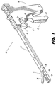
- Fig. 1 is a perspective view of a surgical morcellator apparatus;
- Fig. 2 is an exploded perspective view of the surgical morcellator apparatus of Fig. 1;
- Fig. 3 is a side elevational view in partial cross-section of the surgical morcellator apparatus of Fig. 1 with the upper jaw in an open position;
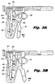
- Fig. 3A is a side elevational view in partial cross-section of the surgical morcellator apparatus of Fig. 1 with the handle member in a first position;
- Fig. 3B is a side elevational view in partial cross-section of the surgical morcellator apparatus of Fig. 1 with the handle member in a second position;
- Fig. 4 is a side elevational view of the surgical morcellator apparatus in conjunction with an endoscopic surgical grasping instrument;
- Fig. 5 is an illustration of a fragmented tissue part being removed from the proximal end of the surgical morcellator apparatus by the endoscopic gripping instrument of Fig. 4;
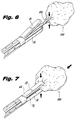
- Figs. 6 and 7 illustrate the capture of tissue during a morcellation procedure employing the surgical morcellator in cooperation with the endoscopic surgical gripping instrument;
- Fig. 8 is a side elevational view in partial cross-section of the jaw assembly of the morcellator device illustrated in Fig. 4 during the fragmenting of the tissue part; and
- Fig. 9 is a top planar view with the top jaw member removed of the surgical morcellator apparatus of Fig. 8.
- In the drawings and in the description which follows, the term "proximal", as is traditional, will refer to the end of the surgical apparatus which is closest to the operator, while the term "distal" will refer to the end of the apparatus which is furthest from the operator.
- An embodiment of the surgical apparatus of the subject application is illustrated in Fig. 1 and is designated generally by
reference numeral 10.Surgical apparatus 10 is configured for fragmenting tissue during endoscopic procedures in which access to the surgical site is limited. In brief, thesurgical instrument 10 includes ahandle assembly 12, anelongated body portion 14 extending longitudinally from thehandle assembly 12 and preferably dimensioned for endoscopic use, and atool assembly 16 operatively associated with thedistal end 18 of theelongated body portion 14. - The
surgical apparatus 10 is particularly adapted to enable the surgeon, preferably with the employment of a surgical grasping instrument 400 (See Fig. 4), to access and draw target tissue into thetool assembly 16 of thesurgical instrument 10. The user can then retain the target tissue in thetool assembly 16 through use of a first actuation mechanism generally designated byreference numeral 17 and fragment the target tissue through use of a second actuation mechanism generally designated byreference numeral 19. - The
first actuation mechanism 17 includes atrigger member 26 associated with thehandle assembly 12 which effectuates actuation of upper and lower cooperatingjaw members second actuation mechanism 19 includes ahandle member 32 associated with thehandle assembly 12 for effectuating reciprocal translation ofblade cutting member 34, relative to the longitudinal axis defined by theelongated body portion 14. Each of these mechanisms, which effectuates the holding and then fragmenting of tissue at a target site, will be discussed in greater detail hereinbelow. - Referring to Figs. 2 and 3, the
handle assembly 12 includes right and left hemi-portions 15a, 15b, respectively. The right and left hemi-portions 15a and 15b may be mounted to one another through any known method of affixation including, for example, a plurality of pins mounted in a plurality of corresponding apertures or by other methods such as sonic welding or gluing. Each of the hemi-portions 15a, 15b are formed with acavity 24 for accommodating various components of the instrument, all of which will be described in greater detail hereinbelow. - The right and left hemi-
portions 15a, 15b of thehandle assembly 12 are also formed with abore 36 for receiving anelongated tube 38. As shown in Fig. 3, the proximal end of theelongated tube 38 extends from the proximal end ofhandle assembly 12, while the distal end ofelongated tube 38 extends from the distal end of thehandle assembly 12. As shown in Fig. 2, the distal end ofelongated tube 38 is provided with a reduced outer diameter 47 and recessedportions 48 and 50. Atubular adapter 51 is mounted to the reduced diameter portion 47. This connection is accomplished by extending the reduced outer diameter 47 into the proximal end 52 of thetubular adapter 51. - With continuing reference to Fig. 2, upper cooperating
jaw member 28 includes a plurality of connectingmembers 54 which enables a pivotal connection between theupper jaw member 28 and thetubular adapter 51 to be made. This connection is accomplished by extending connectingmembers 54 into corresponding slots 58 provided in the distal end oftubular adapter 51. Thereafter, the upper cooperatingjaw member 28 is pivotably secured to thetubular adapter 51 by a pivot pin which is slidably received through apertures which are provided in the open slots 58 and in the plurality of connectingmembers 54. Additionally, the upper cooperatingjaw member 28 defines aninner cavity portion 64 preferably havingteeth 66 formed along the outer periphery thereof configured and dimensioned to secure and engage with tissue, which will be discussed in greater detail hereinbelow. - The lower cooperating
jaw member 30 is formed with a hemi-cylindrical portion 68 at itsproximal end 70. The hemi-cylindrical portion 68 is configured and dimensioned to extend within the distal end oftubular adapter 51. Additionally, the lower cooperatingjaw member 30 defines aninner cavity 72. A cutting blade track 74 in thelower jaw 30 guides theblade cutting member 34 which reciprocally translates in the cutting blade track 74.Blade cutting member 34 is preferably flexible and capable of conforming to an arcuate configuration as shown in Fig. 2, but may be made of any suitable material which can be configured to cut tissue and to fit into cutting blade track 74. - The
blade cutting member 34 extends into the recessedportions 48, 50 ofelongated tube 38, and is received through aninner race 82 defined by thetubular adapter 51. The cuttingmember 34 has opposed ends 78, 80, wherein each end is disposed at a spaced relationship from theouter surface 76 of the proximal end ofelongated tube 38. The cutting blade track 74 is conformed to receive theblade cutting member 34 at a distal end 84 of the lower cooperatingjaw member 30. In particular, reciprocating movement of the cuttingmember 34 is restrained to follow cutting blade track 74. The movement ofblade cutting member 34 with respect to distal end 84 is preferably arcuate.Elongated slots blade member 34 and are in communication withapertures 94, 96 provided in thelower jaw 30 such that restraining pins 98 and 100 pass throughslots apertures 94 and 96. Restraining pins 98, 100 restrain the translational movement of theblade member 34 within the cutting blade track 74 of the lower cooperatingjaw member 30. Additionally, the portion of theelongated blade member 34 disposed in theinner cavity 72 of thelower jaw member 30 is provided with a plurality of teeth 5 configured to engage and cut tissue in response to translational movement of thecutting blade 34. - The
second actuation mechanism 19 includes right and leftactuation arms member 32. Thesecond actuation mechanism 19 allows for remote actuation of theblade cutting member 34. As illustrated in Fig. 2, atop end 110 ofhandle member 32 is formed with acutout 112 which definesupstanding sidewalls elongated portion 116 oftrigger 26 travels between thesidewalls pivot pin 118 which is mounted in apertures provided in the left hemi-portion 15b and right hemi-portion 15a of thehandle assembly 12.Pivot pin 118 extends through elongatedslot 124 provided on theelongated portion 116 of thetrigger 26, and is secured in a corresponding mounting aperture 126 provided in the left hemi-portion 15b and a corresponding mounting aperture in the right hemi-portion 15a of thehandle assembly 12. Thus, thehandle member 32 pivots about thepivot pin 118 while thetrigger 26 translates longitudinally intermediate thesidewalls top end 110 ofhandle member 32. In the embodiment of Fig. 2, the means for effectuating movement of theblade cutting member 34 is the right and leftactuation arms member 32. -
Handle member 32 further includesyoke member 138, extending therefrom. Aroller 139 is held inyoke member 138 by a pin 141 which passes through the center ofroller 139 and is secured in mountingapertures 151, 153 ofyoke member 138. Right and leftactuation arms cavity portion 24 of thehandle assembly 12 by apivot pin 127 extending throughapertures Pivot pin 127 is secured inapertures portions 15a, 15b, respectively. Retraction ofhandle member 32 causesroller 139 to engageleft actuation arm 104 thereby pivotingleft actuation arm 104 aboutpivot pin 127 in the proximal direction. - To enable spring biased actuation of the
handle member 32, proximal ends of cooperatingsprings outs left actuation arm 104 byfasteners 147, 149, while distal ends of the cooperatingsprings cavity 160 provided in the left hemi-portion 15b of thehandle assembly 12 by afastener 161 secured in a corresponding aperture provided in thecavity portion 160. - A
rocker assembly 88 includes arocker mount block 164 and arocker member 174 which functions to move cuttingblade member 34 under tension. Therocker mount block 164 is secured in a corresponding cut-outportion 166 provided in the left hemi-portion 15b of thehandle assembly 12 by afastener 168. Therocker member 174 is pivotably connected withinsidewalls rocker mount block 164.Pivot pin 180 extends through apertures provided on the distal end of themount block 164 and through an aperture 184 provided onrocker member 174. As best illustrated in Fig. 3, therocker mount block 164 is mounted intermediate the right and leftactuation arms cavity portion 24 of thehandle assembly 12. Referring again to Fig. 2, contact surfaces 170, 172 ofrocker member 174 sit incutouts actuation arms Cutouts rocker member 174. - With continuing reference to Fig. 2,
blade mounting blocks actuation arms screws elongated cutting blade 34 to the right and leftactuation arms screws blade cutting member 34 are fixed withinblade slots 200, 201 which are provided in theblade mounting blocks blade cutting member 34 to reciprocally translate relative to the longitudinal axis of theelongated tube 38 in response to movement of theactuation arms handle member 32, which is discussed in greater detail hereinbelow. - Referring now to Fig. 3A in conjunction with Fig. 2, as
handle member 32 is urged in the direction of arrow "A" by the user,roller 139 which is held inyoke member 138 ofhandle member 32, engages and drives leftactuation arm 104 proximally. The end 80 ofblade cutting member 34 is fastened to leftactuation arm 104 viablade mounting block 189, therefore, as the left actuation arm is moved proximally, the end 80 of theblade cutting member 34 is also moved proximally. The movement of end 80 proximally causesblade cutting member 34 to travel in the direction of end 80 in cutting blade track 74 thereby pullingblade end 78 distally. Theend 78 ofblade cutting member 34 is fastened toright actuation arm 102 viablade mounting block 187, therefore as theend 78 ofblade cutting member 34 is moved distally,right actuation arm 102 is also moved distally. Asright actuation arm 102 is moved distally, the ball bearing incutout 186 ofright actuation arm 102 rides oncontact surface 170 ofrocker member 174, rotating therocker member 174 to the left. Referring now to Figs. 3B and 2, whenhandle member 32 is released in the direction of arrow "B", springs 106 and 108 which are mounted within cut-outs left actuation arm 104 pull leftactuation arm 104 distally. The ball bearing incutout 188 ofleft actuation arm 104 rides on contact surface 172 inrocker member 174, thereby rotating therocker member 174 to the right. The rotation ofrocker member 174 to the rightforces contact surface 170 to driveright actuation arm 102 proximally viacutout 186. Proximal motion ofright actuation arm 102 pullsblade end 78 proximally under tension. - Referring to Figs. 2 and 3, the
first actuation mechanism 17 includes thetrigger 26, a Y-shapedpivot shank 250 and a pair of cooperatingcontrol rods first actuation mechanism 17 allows for remote actuation of one or both of the cooperatingjaw members pivot shank 250 and pair of cooperatingcontrol rods jaw members trigger 26. Thecontrol rods elongated tube 38.Bottom portion 256 of thepivot shank 250 pivotably mounts to the proximal portion of thetrigger 26, whereupon the proximal portion of thetrigger 26 extends withinslot 262 provided at thebottom portion 256 of the Y-shapedpivot shank 250. Facilitating this pivotable connection,pivot pin 264 extends through apertures located on the bottom portion of thepivot shank 250 and through a corresponding aperture 270 located on the proximal portion oftrigger 26. In the embodiment of Figs. 2 and 3, the actuation means for providing remote actuation of one or both of the cooperatingjaw members trigger 26, the Y-shapedpivot shank 250 and the cooperatingcontrol rods - The Y-shaped
pivot shank 250 effectively straddles theouter surface 76 of theelongated tube 38 such that theelongated blade member 34 is disposed intermediate thepivot shank 250 and theelongated tube 38. The substantially parallel top ends 272, 274 of the Y-shapedpivot shank 250 are pivotably fastened within raisedportions portions 15a, 15b, respectively, of thehandle assembly 12. The proximal ends of the cooperatingcontrol rods pivot shank 250. To accomplish such fastening, threadedscrews 288, 290 extend proximally through the apertures 284, 286 of the Y-shapedshank 250 and threadingly engage the proximal ends of thecontrol rods screws 288, 290. - The cooperating
control rods outer surface 76 of theelongated tube 38 from the tube's proximal end to the recessedportions 48, 50 at the distal end of theelongated tube 38. At the distal end of theelongated tube 38, the cooperatingcontrol rods portions 48, 50 and through theinner race 82 oftubular adapter 51. The distal ends of the cooperatingcontrol rods tubular adapter 51 and operatively associate with the proximal end of the upper cooperatingjaw member 28. In particular, through manipulation of thetrigger 26, corresponding pivotable movement of the Y-shapedpivot shank 250 is effected which, in turn, projects and retracts thecontrol rods elongated tube 38. This movement actuates theupper jaw member 28. Thus, when the distal ends of the cooperatingcontrol rods tubular adapter 51, theupper jaw member 28 is actuated towards an open position, as shown in Fig. 3. When the distal ends of the cooperatingcontrol rods member 54, theupper jaw member 28 is actuated towards a closed position substantially parallel to the longitudinal axis of theelongated tube 38, as substantially shown in Fig. 7. - A sealing
valve assembly 296 suitable for use in endoscopic procedures is provided at the proximal end of theelongated tube 38 to provide access to bore 133 of theelongated tube 38. - Right and left blade covers 300, 302 are preferably provided along the
outer surface 76 of theelongated tube 38 such that theelongated cutting blade 34 is disposed intermediate ablade cover outer surface 76 of theelongated tube 38. The distal ends of the right and left blade covers 300, 302 are provided with an enlarged configuration being dimensioned to effectively cover the recessedportions 48, 50 at the distal end of theelongated tube 38. Right and left blade covers 300, 302 are affixed to theouter surface 76 of theelongated tube 38 through any known method of affixation including, for example sonic welding or gluing. - Turning to Fig. 4, the
elongated tube 38 of themorcellator apparatus 10 is dimensioned and configured to receive asurgical instrument 400, such as an endoscopic grasper, one such device being disclosed in U.S. Patent Application Serial No. 08/068,296 filed May 27, 1993 which is hereby incorporated by reference, and which is a continuation of U.S. Patent Application Serial No. 07/593,670 filed October 5, 1990. Thesurgical instrument 400 can be slidably received within bore 133 (Figs. 8-9) of theelongated tube 38, via avalve assembly 296, such that atool member 402 which is located at a distal end of thesurgical instrument 400, is extendible from the distal end of cooperatingjaw members surgical instrument 400 and a sample oftarget tissue 500 therethrough.Handle mechanism 410, located at a proximal end of the surgicalgrasping instrument 400, remotely actuates thetool member 402 between an open position and a closed position. It is within the scope of the present application to substitute the surgicalgrasping instrument 400 with other surgical instruments dimensioned and configured to be slidably received within theelongated tube 38 and having atool member 402 which projects from the distal end of the cooperatingjaw members - Referring to Figs. 5-7, the surgical
grasping instrument 400 accesses and secures target tissue within the rigidinner cavities jaw members target tissue 500. Preferably, after completion of the morcellation procedure, thefragmented tissue part 510 may be retracted from the body cavity and themorcellator apparatus 10, by proximally retracting the surgicalgrasping instrument 400 having thefragmented tissue 510 secured within thetool member 402, from the proximal end of themorcellator apparatus 10. - In operation, to introduce the
morcellator apparatus 10 into the abdominal cavity of a patient during an endoscopic morcellation procedure, the upper and lower cooperatingjaw members jaw member 28 is aligned with the longitudinal axis defined by theelongated body portion 14 of theinstrument 10 to facilitate its insertion through an opening or a trocar or cannula device. Once the instrument has been extended into the patient's abdominal cavity, the distal end of the cooperatingjaw members target tissue 500. - Referring to Figs. 4 and 6, with the upper and lower cooperating
jaw members target tissue 500, the user actuates theupper jaw member 28 to its open position by moving thetrigger portion 26 in the direction indicated by arrow "A" in Fig. 4. The user then inserts the surgicalgrasping instrument 400 through thevalve assembly 296 at the proximal end of and through theelongated tube 38, until thetool member 402 of theinstrument 400 projects from the distal end of the cooperatingjaw members tool member 402 then engages thetarget tissue 500 through manipulation of thehandle mechanism 410 of the surgicalgrasping instrument 400. - Referring to Figs. 7 and 8, the
target tissue 500, or a portion thereof, is retracted into the rigidinner cavities grasping instrument 400 in a proximal direction relative to themorcellator apparatus 10, until thetool member 402 of the surgicalgrasping instrument 400 is disposed within the rigidinner cavities jaw members upper jaw member 28 is actuated to its closed position, therein securing the target tissue withininner cavities upper jaw member 28 to its closed position is achieved by moving the trigger portion in the direction indicated by arrow "B", as shown in Fig. 4. - Referring to Figs. 8 and 9, morcellation of the
target tissue 500 is achieved by actuating thehandle member 32 in the direction indicated by arrow "C" (see Fig. 4) which effectuates the arcuately configured cuttingblade 34 to translate in the direction indicted by arrow "D", whereupon thecutting blade 34 cuts and separates thetarget tissue 500 within the rigidinner cavities jaw members fragmented tissue part 510 may be removed from the patient's abdominal cavity by proximally retracting the surgicalgrasping instrument 400, having thefragmented tissue 510 secured thereto, from themorcellator apparatus 10, as illustrated in Fig. 5. Alternatively, the user may remove themorcellator apparatus 10 from the abdominal cavity of the patient, via the trocar or cannula device, whereupon thefragmented tissue part 510 can be removed from within the inner cavity of the cooperatingjaw members - The morcellator instrument described herein is compact, lightweight and easy to use. It is intended to enable the surgeon to use the instrument with one hand, thus freeing the other hand for performance of surgical tasks.
- It will be understood that various modifications may be made to the embodiments described herein. For example, although described in conjunction with a surgical grasping instrument (400), such a surgical grasping instrument need not always be utilized with the morcellator. In addition, although the blade cutting member has been shown in an arcuate configuration, other configurations would also be suitable. The claims which follow identify embodiments of the invention additional to those described in detail above.
Claims (15)
- A surgical apparatus for fragmenting tissue comprising:
a securing mechanism defining an inner cavity; and a cutting member provided in the inner cavity;
wherein the securing mechanism holds the tissue preparatory to the fragmenting of the tissue by the cutting member. - A surgical apparatus as recited in Claim 1, wherein the securing mechanism includes a pair of cooperating jaw members configured for use in remote securing of tissue.
- A surgical apparatus as recited in Claim 2, further comprising a first actuation mechanism associated with the cooperating jaw members for remotely actuating the cooperating jaw members between an open position and a closed position.
- A surgical apparatus as recited in any of the preceding claims, wherein the inner cavity is rigid.
- A surgical apparatus as recited in any of the preceding claims, further comprising a second actuation mechanism operatively associated with the cutting member for effecting movement of the cutting member.
- A surgical apparatus as recited in any of the preceding claims, wherein the movement of the cutting member is reciprocal with respect to the inner cavity.
- A surgical apparatus as recited in any of the preceding claims, further comprising
a handle assembly;
a body portion extending from the handle assembly and defining a longitudinal axis wherein the jaw members are associated with a distal end portion of the body portion. - A surgical apparatus as recited in any of the preceding claims, wherein each of the jaw members is provided with teeth.
- A surgical apparatus as recited in any of the preceding claims, wherein the cutting member includes an arcuately configured cutting blade.
- A surgical apparatus as recited in any of the preceding claims, further comprising a second actuation mechanism associated with the cutting member for effectuating reciprocating, arcuate movement of the cutting member within the at least one jaw member.
- A surgical apparatus as recited in any of the preceding claims, wherein the second actuation mechanism includes a handle member pivotally connected to the handle assembly and at least one actuation arm, the actuation arm interconnecting the handle member to the cutting member.
- A surgical apparatus as recited in any of the preceding claims, further comprising a bore portion having a longitudinal axis defined by a longitudinal axis of the apparatus for accessing the cutting member, the bore being dimensioned to be capable of pulling fragmented tissue therethrough.
- A surgical apparatus as recited in Claim 12, wherein the bore is dimensioned for reception of a grasping member therethrough.
- A surgical apparatus as recited in Claim 13, wherein the grasping member has an elongated body portion including a tool assembly associated with a distal end, and a handle mechanism associated with a proximal end to effectuate remote actuation of the tool assembly between an open position and a closed position.
- A surgical apparatus as recited in any of the preceding claims, wherein the securing mechanism is dimensioned and configured for insertion through a trocar cannula.
Applications Claiming Priority (2)
| Application Number | Priority Date | Filing Date | Title |
|---|---|---|---|
| US08/321,367 US5562694A (en) | 1994-10-11 | 1994-10-11 | Morcellator |
| US321367 | 1994-10-11 |
Publications (3)
| Publication Number | Publication Date |
|---|---|
| EP0706781A2 true EP0706781A2 (en) | 1996-04-17 |
| EP0706781A3 EP0706781A3 (en) | 1996-07-31 |
| EP0706781B1 EP0706781B1 (en) | 2003-04-09 |
Family
ID=23250319
Family Applications (1)
| Application Number | Title | Priority Date | Filing Date |
|---|---|---|---|
| EP95115807A Expired - Lifetime EP0706781B1 (en) | 1994-10-11 | 1995-10-06 | Morcellator |
Country Status (4)
| Country | Link |
|---|---|
| US (1) | US5562694A (en) |
| EP (1) | EP0706781B1 (en) |
| CA (1) | CA2159955A1 (en) |
| DE (1) | DE69530257T2 (en) |
Cited By (6)
| Publication number | Priority date | Publication date | Assignee | Title |
|---|---|---|---|---|
| WO1998024378A1 (en) * | 1996-12-05 | 1998-06-11 | Comedicus Incorporated | Apparatus and method for accessing the pericardial space |
| WO1998049951A1 (en) * | 1997-05-06 | 1998-11-12 | Visco | Modular device for endoscopic surgery and standard surgery |
| US6231518B1 (en) | 1998-05-26 | 2001-05-15 | Comedicus Incorporated | Intrapericardial electrophysiological procedures |
| WO2008040484A2 (en) * | 2006-10-05 | 2008-04-10 | Erbe Elektromedizin Gmbh | Handle for a tubular shaft instrument and tubular shaft instrument comprising a removable handle |
| US10631840B2 (en) | 2015-11-25 | 2020-04-28 | Talon Medical, LLC | Tissue engagement devices, systems, and methods |
| US10667839B2 (en) | 2006-11-01 | 2020-06-02 | Boston Scientific Scimed, Inc. | Tissue removing device |
Families Citing this family (247)
| Publication number | Priority date | Publication date | Assignee | Title |
|---|---|---|---|---|
| US5868760A (en) * | 1994-12-07 | 1999-02-09 | Mcguckin, Jr.; James F. | Method and apparatus for endolumenally resectioning tissue |
| US6120520A (en) | 1997-05-27 | 2000-09-19 | Angiotrax, Inc. | Apparatus and methods for stimulating revascularization and/or tissue growth |
| US6051008A (en) * | 1996-12-02 | 2000-04-18 | Angiotrax, Inc. | Apparatus having stabilization members for percutaneously performing surgery and methods of use |
| US5910150A (en) * | 1996-12-02 | 1999-06-08 | Angiotrax, Inc. | Apparatus for performing surgery |
| US6010476A (en) * | 1996-12-02 | 2000-01-04 | Angiotrax, Inc. | Apparatus for performing transmyocardial revascularization |
| US5899915A (en) * | 1996-12-02 | 1999-05-04 | Angiotrax, Inc. | Apparatus and method for intraoperatively performing surgery |
| US6102926A (en) * | 1996-12-02 | 2000-08-15 | Angiotrax, Inc. | Apparatus for percutaneously performing myocardial revascularization having means for sensing tissue parameters and methods of use |
| US6165188A (en) * | 1996-12-02 | 2000-12-26 | Angiotrax, Inc. | Apparatus for percutaneously performing myocardial revascularization having controlled cutting depth and methods of use |
| US5830231A (en) * | 1997-03-19 | 1998-11-03 | Geiges, Jr.; John J. | Handle and actuating mechanism for surgical instruments |
| US6039748A (en) | 1997-08-05 | 2000-03-21 | Femrx, Inc. | Disposable laparoscopic morcellator |
| US5972012A (en) * | 1997-10-17 | 1999-10-26 | Angiotrax, Inc. | Cutting apparatus having articulable tip |
| AU2001273421A1 (en) | 2000-07-13 | 2002-01-30 | Bioheart, Inc. | Deployment system for myocardial cellular material |
| ES2245692T5 (en) | 2000-07-27 | 2012-01-04 | Synthes Ag Chur | CRANIAL FLAG TIGHTENING DEVICE. |
| US7727246B2 (en) | 2000-12-06 | 2010-06-01 | Ethicon Endo-Surgery, Inc. | Methods for endoluminal treatment |
| US20020138086A1 (en) * | 2000-12-06 | 2002-09-26 | Robert Sixto | Surgical clips particularly useful in the endoluminal treatment of gastroesophageal reflux disease (GERD) |
| US8062314B2 (en) * | 2000-12-06 | 2011-11-22 | Ethicon Endo-Surgery, Inc. | Methods for the endoluminal treatment of gastroesophageal reflux disease (GERD) |
| US6716226B2 (en) * | 2001-06-25 | 2004-04-06 | Inscope Development, Llc | Surgical clip |
| US7232445B2 (en) * | 2000-12-06 | 2007-06-19 | Id, Llc | Apparatus for the endoluminal treatment of gastroesophageal reflux disease (GERD) |
| US20020068945A1 (en) * | 2000-12-06 | 2002-06-06 | Robert Sixto | Surgical clips particularly useful in the endoluminal treatment of gastroesophageal reflux disease (GERD) |
| US6551315B2 (en) * | 2000-12-06 | 2003-04-22 | Syntheon, Llc | Methods and apparatus for the treatment of gastric ulcers |
| JP4202138B2 (en) | 2001-01-31 | 2008-12-24 | レックス メディカル インコーポレイテッド | Apparatus and method for stapling and ablating gastroesophageal tissue |
| US6808491B2 (en) | 2001-05-21 | 2004-10-26 | Syntheon, Llc | Methods and apparatus for on-endoscope instruments having end effectors and combinations of on-endoscope and through-endoscope instruments |
| US20050277956A1 (en) * | 2004-06-14 | 2005-12-15 | Francese Jose L | Clip storage for endoscopic clip applier |
| US6869436B2 (en) | 2002-02-07 | 2005-03-22 | Scimed Life Systems, Inc. | Surgical clip with a self-releasing fluid reservoir |
| US8241308B2 (en) | 2002-04-24 | 2012-08-14 | Boston Scientific Scimed, Inc. | Tissue fastening devices and processes that promote tissue adhesion |
| US8016845B1 (en) * | 2003-02-04 | 2011-09-13 | Lsi Solutions, Inc. | Instrument for guiding the surgical cutting of tissue and method of use |
| US7481817B2 (en) * | 2003-02-13 | 2009-01-27 | Lsi Soultions, Inc. | Instrument for surgically cutting tissue and method of use |
| US7105000B2 (en) * | 2003-03-25 | 2006-09-12 | Ethicon Endo-Surgery, Inc. | Surgical jaw assembly with increased mechanical advantage |
| US20040193188A1 (en) * | 2003-03-25 | 2004-09-30 | Inscope Development, Llc | Laminated surgical clip |
| US20040193189A1 (en) * | 2003-03-25 | 2004-09-30 | Kortenbach Juergen A. | Passive surgical clip |
| US20070084897A1 (en) | 2003-05-20 | 2007-04-19 | Shelton Frederick E Iv | Articulating surgical stapling instrument incorporating a two-piece e-beam firing mechanism |
| US9060770B2 (en) | 2003-05-20 | 2015-06-23 | Ethicon Endo-Surgery, Inc. | Robotically-driven surgical instrument with E-beam driver |
| US8308708B2 (en) | 2003-07-15 | 2012-11-13 | Abbott Cardiovascular Systems Inc. | Deployment system for myocardial cellular material |
| DE102004021713A1 (en) | 2004-04-30 | 2005-11-17 | Karl Storz Gmbh & Co. Kg | Arrangement of medical instruments for surgical purposes |
| GB2414185A (en) * | 2004-05-20 | 2005-11-23 | Gyrus Medical Ltd | Morcellating device using cutting electrodes on end-face of tube |
| US8216255B2 (en) * | 2004-06-14 | 2012-07-10 | Ethicon Endo-Surgery, Inc. | Endoscopic clip applier actuator |
| US11896225B2 (en) | 2004-07-28 | 2024-02-13 | Cilag Gmbh International | Staple cartridge comprising a pan |
| US7686820B2 (en) | 2005-04-14 | 2010-03-30 | Ethicon Endo-Surgery, Inc. | Surgical clip applier ratchet mechanism |
| US7288098B2 (en) | 2005-04-14 | 2007-10-30 | Ethicon Endo-Surgery, Inc. | Force limiting mechanism for medical instrument |
| US7740641B2 (en) | 2005-04-14 | 2010-06-22 | Ethicon Endo-Surgery, Inc. | Clip applier with migrational resistance features |
| US7731724B2 (en) | 2005-04-14 | 2010-06-08 | Ethicon Endo-Surgery, Inc. | Surgical clip advancement and alignment mechanism |
| US8038686B2 (en) | 2005-04-14 | 2011-10-18 | Ethicon Endo-Surgery, Inc. | Clip applier configured to prevent clip fallout |
| US7297149B2 (en) | 2005-04-14 | 2007-11-20 | Ethicon Endo-Surgery, Inc. | Surgical clip applier methods |
| US8523882B2 (en) | 2005-04-14 | 2013-09-03 | Ethicon Endo-Surgery, Inc. | Clip advancer mechanism with alignment features |
| US7261724B2 (en) | 2005-04-14 | 2007-08-28 | Ethicon Endo-Surgery, Inc. | Surgical clip advancement mechanism |
| US11246590B2 (en) | 2005-08-31 | 2022-02-15 | Cilag Gmbh International | Staple cartridge including staple drivers having different unfired heights |
| US10159482B2 (en) | 2005-08-31 | 2018-12-25 | Ethicon Llc | Fastener cartridge assembly comprising a fixed anvil and different staple heights |
| US7669746B2 (en) | 2005-08-31 | 2010-03-02 | Ethicon Endo-Surgery, Inc. | Staple cartridges for forming staples having differing formed staple heights |
| US20070106317A1 (en) | 2005-11-09 | 2007-05-10 | Shelton Frederick E Iv | Hydraulically and electrically actuated articulation joints for surgical instruments |
| US20120292367A1 (en) | 2006-01-31 | 2012-11-22 | Ethicon Endo-Surgery, Inc. | Robotically-controlled end effector |
| US8708213B2 (en) | 2006-01-31 | 2014-04-29 | Ethicon Endo-Surgery, Inc. | Surgical instrument having a feedback system |
| US7845537B2 (en) | 2006-01-31 | 2010-12-07 | Ethicon Endo-Surgery, Inc. | Surgical instrument having recording capabilities |
| US11793518B2 (en) | 2006-01-31 | 2023-10-24 | Cilag Gmbh International | Powered surgical instruments with firing system lockout arrangements |
| US8186555B2 (en) | 2006-01-31 | 2012-05-29 | Ethicon Endo-Surgery, Inc. | Motor-driven surgical cutting and fastening instrument with mechanical closure system |
| US8820603B2 (en) | 2006-01-31 | 2014-09-02 | Ethicon Endo-Surgery, Inc. | Accessing data stored in a memory of a surgical instrument |
| US20110290856A1 (en) | 2006-01-31 | 2011-12-01 | Ethicon Endo-Surgery, Inc. | Robotically-controlled surgical instrument with force-feedback capabilities |
| US20080039883A1 (en) * | 2006-08-10 | 2008-02-14 | Nohilly Martin J | Anti-coring device for a surgical morcellator |
| US20080039880A1 (en) * | 2006-08-10 | 2008-02-14 | Nohilly Martin J | Cutting blade for morcellator |
| US8100928B2 (en) * | 2006-08-10 | 2012-01-24 | Ethicon, Inc. | Morcellator with detachable handle |
| GB2441501A (en) * | 2006-09-07 | 2008-03-12 | Gyrus Medical Ltd | Surgical instrument with sealing mechanism to retain pressurised gas |
| GB2441502A (en) * | 2006-09-07 | 2008-03-12 | Gyrus Medical Ltd | A morcellating device including a stop mechanism |
| US10568652B2 (en) | 2006-09-29 | 2020-02-25 | Ethicon Llc | Surgical staples having attached drivers of different heights and stapling instruments for deploying the same |
| US9028520B2 (en) | 2006-12-22 | 2015-05-12 | The Spectranetics Corporation | Tissue separating systems and methods |
| US8961551B2 (en) | 2006-12-22 | 2015-02-24 | The Spectranetics Corporation | Retractable separating systems and methods |
| US8684253B2 (en) | 2007-01-10 | 2014-04-01 | Ethicon Endo-Surgery, Inc. | Surgical instrument with wireless communication between a control unit of a robotic system and remote sensor |
| US8701958B2 (en) | 2007-01-11 | 2014-04-22 | Ethicon Endo-Surgery, Inc. | Curved end effector for a surgical stapling device |
| US8931682B2 (en) | 2007-06-04 | 2015-01-13 | Ethicon Endo-Surgery, Inc. | Robotically-controlled shaft based rotary drive systems for surgical instruments |
| US11672531B2 (en) | 2007-06-04 | 2023-06-13 | Cilag Gmbh International | Rotary drive systems for surgical instruments |
| US11849941B2 (en) | 2007-06-29 | 2023-12-26 | Cilag Gmbh International | Staple cartridge having staple cavities extending at a transverse angle relative to a longitudinal cartridge axis |
| US8636736B2 (en) | 2008-02-14 | 2014-01-28 | Ethicon Endo-Surgery, Inc. | Motorized surgical cutting and fastening instrument |
| BRPI0901282A2 (en) | 2008-02-14 | 2009-11-17 | Ethicon Endo Surgery Inc | surgical cutting and fixation instrument with rf electrodes |
| US9005230B2 (en) | 2008-09-23 | 2015-04-14 | Ethicon Endo-Surgery, Inc. | Motorized surgical instrument |
| US11648005B2 (en) | 2008-09-23 | 2023-05-16 | Cilag Gmbh International | Robotically-controlled motorized surgical instrument with an end effector |
| US8210411B2 (en) | 2008-09-23 | 2012-07-03 | Ethicon Endo-Surgery, Inc. | Motor-driven surgical cutting instrument |
| US9386983B2 (en) | 2008-09-23 | 2016-07-12 | Ethicon Endo-Surgery, Llc | Robotically-controlled motorized surgical instrument |
| US8608045B2 (en) | 2008-10-10 | 2013-12-17 | Ethicon Endo-Sugery, Inc. | Powered surgical cutting and stapling apparatus with manually retractable firing system |
| JP5820271B2 (en) | 2008-10-20 | 2015-11-24 | スパイン ビュー, インコーポレイテッド | Retractor cannula system and related methods for spinal access and visualization |
| US8262679B2 (en) | 2009-10-09 | 2012-09-11 | Ethicon Endo-Surgery, Inc. | Clip advancer |
| US8267945B2 (en) | 2009-10-09 | 2012-09-18 | Ethicon Endo-Surgery, Inc. | Clip advancer with lockout mechanism |
| US9386988B2 (en) | 2010-09-30 | 2016-07-12 | Ethicon End-Surgery, LLC | Retainer assembly including a tissue thickness compensator |
| US9629814B2 (en) | 2010-09-30 | 2017-04-25 | Ethicon Endo-Surgery, Llc | Tissue thickness compensator configured to redistribute compressive forces |
| US11925354B2 (en) | 2010-09-30 | 2024-03-12 | Cilag Gmbh International | Staple cartridge comprising staples positioned within a compressible portion thereof |
| US11812965B2 (en) | 2010-09-30 | 2023-11-14 | Cilag Gmbh International | Layer of material for a surgical end effector |
| US10945731B2 (en) | 2010-09-30 | 2021-03-16 | Ethicon Llc | Tissue thickness compensator comprising controlled release and expansion |
| US9700317B2 (en) | 2010-09-30 | 2017-07-11 | Ethicon Endo-Surgery, Llc | Fastener cartridge comprising a releasable tissue thickness compensator |
| US9113865B2 (en) | 2010-09-30 | 2015-08-25 | Ethicon Endo-Surgery, Inc. | Staple cartridge comprising a layer |
| US10022179B2 (en) | 2010-12-14 | 2018-07-17 | Ethicon, Inc. | Bipolar medical devices for extracting tissue and methods therefor |
| AU2012250197B2 (en) | 2011-04-29 | 2017-08-10 | Ethicon Endo-Surgery, Inc. | Staple cartridge comprising staples positioned within a compressible portion thereof |
| US9072535B2 (en) | 2011-05-27 | 2015-07-07 | Ethicon Endo-Surgery, Inc. | Surgical stapling instruments with rotatable staple deployment arrangements |
| WO2013059432A1 (en) | 2011-10-19 | 2013-04-25 | Ethicon Endo-Surgery, Inc. | Clip applier adapted for use with a surgical robot |
| JP6305979B2 (en) | 2012-03-28 | 2018-04-04 | エシコン・エンド−サージェリィ・インコーポレイテッドEthicon Endo−Surgery,Inc. | Tissue thickness compensator with multiple layers |
| BR112014024098B1 (en) | 2012-03-28 | 2021-05-25 | Ethicon Endo-Surgery, Inc. | staple cartridge |
| US9101358B2 (en) | 2012-06-15 | 2015-08-11 | Ethicon Endo-Surgery, Inc. | Articulatable surgical instrument comprising a firing drive |
| US9282974B2 (en) | 2012-06-28 | 2016-03-15 | Ethicon Endo-Surgery, Llc | Empty clip cartridge lockout |
| US9289256B2 (en) | 2012-06-28 | 2016-03-22 | Ethicon Endo-Surgery, Llc | Surgical end effectors having angled tissue-contacting surfaces |
| US20140001231A1 (en) | 2012-06-28 | 2014-01-02 | Ethicon Endo-Surgery, Inc. | Firing system lockout arrangements for surgical instruments |
| US9408606B2 (en) | 2012-06-28 | 2016-08-09 | Ethicon Endo-Surgery, Llc | Robotically powered surgical device with manually-actuatable reversing system |
| US9724122B2 (en) | 2012-09-14 | 2017-08-08 | The Spectranetics Corporation | Expandable lead jacket |
| WO2014123571A1 (en) | 2013-02-05 | 2014-08-14 | University Of South Florida | Minimally invasive laparoscopic tissue removal device |
| BR112015021098B1 (en) | 2013-03-01 | 2022-02-15 | Ethicon Endo-Surgery, Inc | COVERAGE FOR A JOINT JOINT AND SURGICAL INSTRUMENT |
| US10383691B2 (en) | 2013-03-13 | 2019-08-20 | The Spectranetics Corporation | Last catheter with helical internal lumen |
| US9883885B2 (en) | 2013-03-13 | 2018-02-06 | The Spectranetics Corporation | System and method of ablative cutting and pulsed vacuum aspiration |
| US9283040B2 (en) | 2013-03-13 | 2016-03-15 | The Spectranetics Corporation | Device and method of ablative cutting with helical tip |
| US9291663B2 (en) | 2013-03-13 | 2016-03-22 | The Spectranetics Corporation | Alarm for lead insulation abnormality |
| US9456872B2 (en) | 2013-03-13 | 2016-10-04 | The Spectranetics Corporation | Laser ablation catheter |
| US10835279B2 (en) | 2013-03-14 | 2020-11-17 | Spectranetics Llc | Distal end supported tissue slitting apparatus |
| WO2014151814A1 (en) | 2013-03-15 | 2014-09-25 | The Spectranetics Corporation | Surgical instrument for removing an implanted object |
| US9668765B2 (en) | 2013-03-15 | 2017-06-06 | The Spectranetics Corporation | Retractable blade for lead removal device |
| US10842532B2 (en) | 2013-03-15 | 2020-11-24 | Spectranetics Llc | Medical device for removing an implanted object |
| WO2017048486A1 (en) | 2013-03-15 | 2017-03-23 | The Spectranetics Corporation | Medical device for removing an implanted object using laser cut hypotubes |
| US9603618B2 (en) | 2013-03-15 | 2017-03-28 | The Spectranetics Corporation | Medical device for removing an implanted object |
| US10136913B2 (en) | 2013-03-15 | 2018-11-27 | The Spectranetics Corporation | Multiple configuration surgical cutting device |
| US10448999B2 (en) | 2013-03-15 | 2019-10-22 | The Spectranetics Corporation | Surgical instrument for removing an implanted object |
| BR112015026109B1 (en) | 2013-04-16 | 2022-02-22 | Ethicon Endo-Surgery, Inc | surgical instrument |
| US9924942B2 (en) | 2013-08-23 | 2018-03-27 | Ethicon Llc | Motor-powered articulatable surgical instruments |
| US9804618B2 (en) | 2014-03-26 | 2017-10-31 | Ethicon Llc | Systems and methods for controlling a segmented circuit |
| US20150297222A1 (en) | 2014-04-16 | 2015-10-22 | Ethicon Endo-Surgery, Inc. | Fastener cartridges including extensions having different configurations |
| JP6532889B2 (en) | 2014-04-16 | 2019-06-19 | エシコン エルエルシーEthicon LLC | Fastener cartridge assembly and staple holder cover arrangement |
| CN106456176B (en) | 2014-04-16 | 2019-06-28 | 伊西康内外科有限责任公司 | Fastener cartridge including the extension with various configuration |
| US10405924B2 (en) | 2014-05-30 | 2019-09-10 | The Spectranetics Corporation | System and method of ablative cutting and vacuum aspiration through primary orifice and auxiliary side port |
| WO2016018457A1 (en) * | 2014-07-31 | 2016-02-04 | Smith & Nephew, Inc. | Surgical endoscopic cutting system |
| BR112017004361B1 (en) | 2014-09-05 | 2023-04-11 | Ethicon Llc | ELECTRONIC SYSTEM FOR A SURGICAL INSTRUMENT |
| US10135242B2 (en) | 2014-09-05 | 2018-11-20 | Ethicon Llc | Smart cartridge wake up operation and data retention |
| US9924944B2 (en) | 2014-10-16 | 2018-03-27 | Ethicon Llc | Staple cartridge comprising an adjunct material |
| US11141153B2 (en) | 2014-10-29 | 2021-10-12 | Cilag Gmbh International | Staple cartridges comprising driver arrangements |
| US10517594B2 (en) | 2014-10-29 | 2019-12-31 | Ethicon Llc | Cartridge assemblies for surgical staplers |
| US10004501B2 (en) | 2014-12-18 | 2018-06-26 | Ethicon Llc | Surgical instruments with improved closure arrangements |
| US10085748B2 (en) | 2014-12-18 | 2018-10-02 | Ethicon Llc | Locking arrangements for detachable shaft assemblies with articulatable surgical end effectors |
| US9987000B2 (en) | 2014-12-18 | 2018-06-05 | Ethicon Llc | Surgical instrument assembly comprising a flexible articulation system |
| RU2703684C2 (en) | 2014-12-18 | 2019-10-21 | ЭТИКОН ЭНДО-СЕРДЖЕРИ, ЭлЭлСи | Surgical instrument with anvil which is selectively movable relative to staple cartridge around discrete fixed axis |
| USD765243S1 (en) | 2015-02-20 | 2016-08-30 | The Spectranetics Corporation | Medical device handle |
| USD770616S1 (en) | 2015-02-20 | 2016-11-01 | The Spectranetics Corporation | Medical device handle |
| US11154301B2 (en) | 2015-02-27 | 2021-10-26 | Cilag Gmbh International | Modular stapling assembly |
| JP2020121162A (en) | 2015-03-06 | 2020-08-13 | エシコン エルエルシーEthicon LLC | Time dependent evaluation of sensor data to determine stability element, creep element and viscoelastic element of measurement |
| US10441279B2 (en) | 2015-03-06 | 2019-10-15 | Ethicon Llc | Multiple level thresholds to modify operation of powered surgical instruments |
| US10390825B2 (en) | 2015-03-31 | 2019-08-27 | Ethicon Llc | Surgical instrument with progressive rotary drive systems |
| US10398459B2 (en) | 2015-04-02 | 2019-09-03 | Aod Holdings Llc | Combination device for endoscopic and arthroscopic surgical procedures |
| US10405839B2 (en) | 2015-04-08 | 2019-09-10 | Altor Health LLC | Organic specimen orientation, segmentation and retrieval device |
| US10105139B2 (en) | 2015-09-23 | 2018-10-23 | Ethicon Llc | Surgical stapler having downstream current-based motor control |
| US10285699B2 (en) | 2015-09-30 | 2019-05-14 | Ethicon Llc | Compressible adjunct |
| US11890015B2 (en) | 2015-09-30 | 2024-02-06 | Cilag Gmbh International | Compressible adjunct with crossing spacer fibers |
| US10292704B2 (en) | 2015-12-30 | 2019-05-21 | Ethicon Llc | Mechanisms for compensating for battery pack failure in powered surgical instruments |
| US10507036B2 (en) | 2016-01-13 | 2019-12-17 | Covidien LLP | Tissue-removing catheter, tissue-removing element, and method of making same |
| US11213293B2 (en) | 2016-02-09 | 2022-01-04 | Cilag Gmbh International | Articulatable surgical instruments with single articulation link arrangements |
| US10448948B2 (en) | 2016-02-12 | 2019-10-22 | Ethicon Llc | Mechanisms for compensating for drivetrain failure in powered surgical instruments |
| US10828028B2 (en) | 2016-04-15 | 2020-11-10 | Ethicon Llc | Surgical instrument with multiple program responses during a firing motion |
| US10357247B2 (en) | 2016-04-15 | 2019-07-23 | Ethicon Llc | Surgical instrument with multiple program responses during a firing motion |
| US10426467B2 (en) | 2016-04-15 | 2019-10-01 | Ethicon Llc | Surgical instrument with detection sensors |
| US10478181B2 (en) | 2016-04-18 | 2019-11-19 | Ethicon Llc | Cartridge lockout arrangements for rotary powered surgical cutting and stapling instruments |
| US20170296173A1 (en) | 2016-04-18 | 2017-10-19 | Ethicon Endo-Surgery, Llc | Method for operating a surgical instrument |
| US20180168625A1 (en) | 2016-12-21 | 2018-06-21 | Ethicon Endo-Surgery, Llc | Surgical stapling instruments with smart staple cartridges |
| US10517595B2 (en) | 2016-12-21 | 2019-12-31 | Ethicon Llc | Jaw actuated lock arrangements for preventing advancement of a firing member in a surgical end effector unless an unfired cartridge is installed in the end effector |
| US10675026B2 (en) | 2016-12-21 | 2020-06-09 | Ethicon Llc | Methods of stapling tissue |
| US10675025B2 (en) | 2016-12-21 | 2020-06-09 | Ethicon Llc | Shaft assembly comprising separately actuatable and retractable systems |
| US20180168615A1 (en) | 2016-12-21 | 2018-06-21 | Ethicon Endo-Surgery, Llc | Method of deforming staples from two different types of staple cartridges with the same surgical stapling instrument |
| JP7010956B2 (en) | 2016-12-21 | 2022-01-26 | エシコン エルエルシー | How to staple tissue |
| US10987131B2 (en) | 2017-05-25 | 2021-04-27 | Coopersurgical, Inc. | Tissue containment systems and related methods |
| US10779820B2 (en) | 2017-06-20 | 2020-09-22 | Ethicon Llc | Systems and methods for controlling motor speed according to user input for a surgical instrument |
| US11517325B2 (en) | 2017-06-20 | 2022-12-06 | Cilag Gmbh International | Closed loop feedback control of motor velocity of a surgical stapling and cutting instrument based on measured displacement distance traveled over a specified time interval |
| US11653914B2 (en) | 2017-06-20 | 2023-05-23 | Cilag Gmbh International | Systems and methods for controlling motor velocity of a surgical stapling and cutting instrument according to articulation angle of end effector |
| US10881399B2 (en) | 2017-06-20 | 2021-01-05 | Ethicon Llc | Techniques for adaptive control of motor velocity of a surgical stapling and cutting instrument |
| US10307170B2 (en) | 2017-06-20 | 2019-06-04 | Ethicon Llc | Method for closed loop control of motor velocity of a surgical stapling and cutting instrument |
| US10993716B2 (en) | 2017-06-27 | 2021-05-04 | Ethicon Llc | Surgical anvil arrangements |
| US10765427B2 (en) | 2017-06-28 | 2020-09-08 | Ethicon Llc | Method for articulating a surgical instrument |
| EP3420947B1 (en) | 2017-06-28 | 2022-05-25 | Cilag GmbH International | Surgical instrument comprising selectively actuatable rotatable couplers |
| US11678880B2 (en) | 2017-06-28 | 2023-06-20 | Cilag Gmbh International | Surgical instrument comprising a shaft including a housing arrangement |
| US11020114B2 (en) | 2017-06-28 | 2021-06-01 | Cilag Gmbh International | Surgical instruments with articulatable end effector with axially shortened articulation joint configurations |
| USD906355S1 (en) | 2017-06-28 | 2020-12-29 | Ethicon Llc | Display screen or portion thereof with a graphical user interface for a surgical instrument |
| US11564686B2 (en) | 2017-06-28 | 2023-01-31 | Cilag Gmbh International | Surgical shaft assemblies with flexible interfaces |
| US10932772B2 (en) | 2017-06-29 | 2021-03-02 | Ethicon Llc | Methods for closed loop velocity control for robotic surgical instrument |
| US11944300B2 (en) | 2017-08-03 | 2024-04-02 | Cilag Gmbh International | Method for operating a surgical system bailout |
| US10779826B2 (en) | 2017-12-15 | 2020-09-22 | Ethicon Llc | Methods of operating surgical end effectors |
| US11179151B2 (en) | 2017-12-21 | 2021-11-23 | Cilag Gmbh International | Surgical instrument comprising a display |
| US11696761B2 (en) | 2019-03-25 | 2023-07-11 | Cilag Gmbh International | Firing drive arrangements for surgical systems |
| US11903581B2 (en) | 2019-04-30 | 2024-02-20 | Cilag Gmbh International | Methods for stapling tissue using a surgical instrument |
| US11648009B2 (en) | 2019-04-30 | 2023-05-16 | Cilag Gmbh International | Rotatable jaw tip for a surgical instrument |
| US11627959B2 (en) | 2019-06-28 | 2023-04-18 | Cilag Gmbh International | Surgical instruments including manual and powered system lockouts |
| US11229437B2 (en) | 2019-06-28 | 2022-01-25 | Cilag Gmbh International | Method for authenticating the compatibility of a staple cartridge with a surgical instrument |
| US11523822B2 (en) | 2019-06-28 | 2022-12-13 | Cilag Gmbh International | Battery pack including a circuit interrupter |
| US11684434B2 (en) | 2019-06-28 | 2023-06-27 | Cilag Gmbh International | Surgical RFID assemblies for instrument operational setting control |
| US11771419B2 (en) | 2019-06-28 | 2023-10-03 | Cilag Gmbh International | Packaging for a replaceable component of a surgical stapling system |
| US11660163B2 (en) | 2019-06-28 | 2023-05-30 | Cilag Gmbh International | Surgical system with RFID tags for updating motor assembly parameters |
| US11553971B2 (en) | 2019-06-28 | 2023-01-17 | Cilag Gmbh International | Surgical RFID assemblies for display and communication |
| US11638587B2 (en) | 2019-06-28 | 2023-05-02 | Cilag Gmbh International | RFID identification systems for surgical instruments |
| US11529137B2 (en) | 2019-12-19 | 2022-12-20 | Cilag Gmbh International | Staple cartridge comprising driver retention members |
| US11576672B2 (en) | 2019-12-19 | 2023-02-14 | Cilag Gmbh International | Surgical instrument comprising a closure system including a closure member and an opening member driven by a drive screw |
| US11559304B2 (en) | 2019-12-19 | 2023-01-24 | Cilag Gmbh International | Surgical instrument comprising a rapid closure mechanism |
| US11911032B2 (en) | 2019-12-19 | 2024-02-27 | Cilag Gmbh International | Staple cartridge comprising a seating cam |
| US11844520B2 (en) | 2019-12-19 | 2023-12-19 | Cilag Gmbh International | Staple cartridge comprising driver retention members |
| US11607219B2 (en) | 2019-12-19 | 2023-03-21 | Cilag Gmbh International | Staple cartridge comprising a detachable tissue cutting knife |
| US11701111B2 (en) * | 2019-12-19 | 2023-07-18 | Cilag Gmbh International | Method for operating a surgical stapling instrument |
| USD976401S1 (en) | 2020-06-02 | 2023-01-24 | Cilag Gmbh International | Staple cartridge |
| USD975850S1 (en) | 2020-06-02 | 2023-01-17 | Cilag Gmbh International | Staple cartridge |
| USD974560S1 (en) | 2020-06-02 | 2023-01-03 | Cilag Gmbh International | Staple cartridge |
| USD975851S1 (en) | 2020-06-02 | 2023-01-17 | Cilag Gmbh International | Staple cartridge |
| US20220031350A1 (en) | 2020-07-28 | 2022-02-03 | Cilag Gmbh International | Surgical instruments with double pivot articulation joint arrangements |
| US11896217B2 (en) | 2020-10-29 | 2024-02-13 | Cilag Gmbh International | Surgical instrument comprising an articulation lock |
| US11534259B2 (en) | 2020-10-29 | 2022-12-27 | Cilag Gmbh International | Surgical instrument comprising an articulation indicator |
| US11931025B2 (en) | 2020-10-29 | 2024-03-19 | Cilag Gmbh International | Surgical instrument comprising a releasable closure drive lock |
| USD1013170S1 (en) | 2020-10-29 | 2024-01-30 | Cilag Gmbh International | Surgical instrument assembly |
| USD980425S1 (en) | 2020-10-29 | 2023-03-07 | Cilag Gmbh International | Surgical instrument assembly |
| US11617577B2 (en) | 2020-10-29 | 2023-04-04 | Cilag Gmbh International | Surgical instrument comprising a sensor configured to sense whether an articulation drive of the surgical instrument is actuatable |
| US11844518B2 (en) | 2020-10-29 | 2023-12-19 | Cilag Gmbh International | Method for operating a surgical instrument |
| US11517390B2 (en) | 2020-10-29 | 2022-12-06 | Cilag Gmbh International | Surgical instrument comprising a limited travel switch |
| US11717289B2 (en) | 2020-10-29 | 2023-08-08 | Cilag Gmbh International | Surgical instrument comprising an indicator which indicates that an articulation drive is actuatable |
| US11779330B2 (en) | 2020-10-29 | 2023-10-10 | Cilag Gmbh International | Surgical instrument comprising a jaw alignment system |
| US11849943B2 (en) | 2020-12-02 | 2023-12-26 | Cilag Gmbh International | Surgical instrument with cartridge release mechanisms |
| US11678882B2 (en) | 2020-12-02 | 2023-06-20 | Cilag Gmbh International | Surgical instruments with interactive features to remedy incidental sled movements |
| US11653915B2 (en) | 2020-12-02 | 2023-05-23 | Cilag Gmbh International | Surgical instruments with sled location detection and adjustment features |
| US11890010B2 (en) | 2020-12-02 | 2024-02-06 | Cllag GmbH International | Dual-sided reinforced reload for surgical instruments |
| US11627960B2 (en) | 2020-12-02 | 2023-04-18 | Cilag Gmbh International | Powered surgical instruments with smart reload with separately attachable exteriorly mounted wiring connections |
| US11737751B2 (en) | 2020-12-02 | 2023-08-29 | Cilag Gmbh International | Devices and methods of managing energy dissipated within sterile barriers of surgical instrument housings |
| US11653920B2 (en) | 2020-12-02 | 2023-05-23 | Cilag Gmbh International | Powered surgical instruments with communication interfaces through sterile barrier |
| US11944296B2 (en) | 2020-12-02 | 2024-04-02 | Cilag Gmbh International | Powered surgical instruments with external connectors |
| US11744581B2 (en) | 2020-12-02 | 2023-09-05 | Cilag Gmbh International | Powered surgical instruments with multi-phase tissue treatment |
| US11730473B2 (en) | 2021-02-26 | 2023-08-22 | Cilag Gmbh International | Monitoring of manufacturing life-cycle |
| US11751869B2 (en) | 2021-02-26 | 2023-09-12 | Cilag Gmbh International | Monitoring of multiple sensors over time to detect moving characteristics of tissue |
| US11749877B2 (en) | 2021-02-26 | 2023-09-05 | Cilag Gmbh International | Stapling instrument comprising a signal antenna |
| US11925349B2 (en) | 2021-02-26 | 2024-03-12 | Cilag Gmbh International | Adjustment to transfer parameters to improve available power |
| US11696757B2 (en) | 2021-02-26 | 2023-07-11 | Cilag Gmbh International | Monitoring of internal systems to detect and track cartridge motion status |
| US11723657B2 (en) | 2021-02-26 | 2023-08-15 | Cilag Gmbh International | Adjustable communication based on available bandwidth and power capacity |
| US11744583B2 (en) | 2021-02-26 | 2023-09-05 | Cilag Gmbh International | Distal communication array to tune frequency of RF systems |
| US11793514B2 (en) | 2021-02-26 | 2023-10-24 | Cilag Gmbh International | Staple cartridge comprising sensor array which may be embedded in cartridge body |
| US11812964B2 (en) | 2021-02-26 | 2023-11-14 | Cilag Gmbh International | Staple cartridge comprising a power management circuit |
| US11701113B2 (en) | 2021-02-26 | 2023-07-18 | Cilag Gmbh International | Stapling instrument comprising a separate power antenna and a data transfer antenna |
| US11826042B2 (en) | 2021-03-22 | 2023-11-28 | Cilag Gmbh International | Surgical instrument comprising a firing drive including a selectable leverage mechanism |
| US11737749B2 (en) | 2021-03-22 | 2023-08-29 | Cilag Gmbh International | Surgical stapling instrument comprising a retraction system |
| US11759202B2 (en) | 2021-03-22 | 2023-09-19 | Cilag Gmbh International | Staple cartridge comprising an implantable layer |
| US11826012B2 (en) | 2021-03-22 | 2023-11-28 | Cilag Gmbh International | Stapling instrument comprising a pulsed motor-driven firing rack |
| US11806011B2 (en) | 2021-03-22 | 2023-11-07 | Cilag Gmbh International | Stapling instrument comprising tissue compression systems |
| US11723658B2 (en) | 2021-03-22 | 2023-08-15 | Cilag Gmbh International | Staple cartridge comprising a firing lockout |
| US11717291B2 (en) | 2021-03-22 | 2023-08-08 | Cilag Gmbh International | Staple cartridge comprising staples configured to apply different tissue compression |
| US11903582B2 (en) | 2021-03-24 | 2024-02-20 | Cilag Gmbh International | Leveraging surfaces for cartridge installation |
| US11857183B2 (en) | 2021-03-24 | 2024-01-02 | Cilag Gmbh International | Stapling assembly components having metal substrates and plastic bodies |
| US11944336B2 (en) | 2021-03-24 | 2024-04-02 | Cilag Gmbh International | Joint arrangements for multi-planar alignment and support of operational drive shafts in articulatable surgical instruments |
| US11849944B2 (en) | 2021-03-24 | 2023-12-26 | Cilag Gmbh International | Drivers for fastener cartridge assemblies having rotary drive screws |
| US11896218B2 (en) | 2021-03-24 | 2024-02-13 | Cilag Gmbh International | Method of using a powered stapling device |
| US11849945B2 (en) | 2021-03-24 | 2023-12-26 | Cilag Gmbh International | Rotary-driven surgical stapling assembly comprising eccentrically driven firing member |
| US11744603B2 (en) | 2021-03-24 | 2023-09-05 | Cilag Gmbh International | Multi-axis pivot joints for surgical instruments and methods for manufacturing same |
| US11832816B2 (en) | 2021-03-24 | 2023-12-05 | Cilag Gmbh International | Surgical stapling assembly comprising nonplanar staples and planar staples |
| US11793516B2 (en) | 2021-03-24 | 2023-10-24 | Cilag Gmbh International | Surgical staple cartridge comprising longitudinal support beam |
| US11896219B2 (en) | 2021-03-24 | 2024-02-13 | Cilag Gmbh International | Mating features between drivers and underside of a cartridge deck |
| US11786243B2 (en) | 2021-03-24 | 2023-10-17 | Cilag Gmbh International | Firing members having flexible portions for adapting to a load during a surgical firing stroke |
| US11786239B2 (en) | 2021-03-24 | 2023-10-17 | Cilag Gmbh International | Surgical instrument articulation joint arrangements comprising multiple moving linkage features |
| US20220378426A1 (en) | 2021-05-28 | 2022-12-01 | Cilag Gmbh International | Stapling instrument comprising a mounted shaft orientation sensor |
| US20230000495A1 (en) * | 2021-06-30 | 2023-01-05 | Covidien Lp | Circular stapling device with tissue grasping members |
| US11937816B2 (en) | 2021-10-28 | 2024-03-26 | Cilag Gmbh International | Electrical lead arrangements for surgical instruments |
Citations (3)
| Publication number | Priority date | Publication date | Assignee | Title |
|---|---|---|---|---|
| US4428375A (en) | 1982-02-16 | 1984-01-31 | Ellman Barry R | Surgical bag for splenorrhaphy |
| US5215521A (en) | 1991-11-26 | 1993-06-01 | Cochran James C | Laparoscopy organ retrieval apparatus and procedure |
| US6829693B2 (en) | 2001-02-28 | 2004-12-07 | International Business Machines Corporation | Auxiliary storage slot scavenger |
Family Cites Families (50)
| Publication number | Priority date | Publication date | Assignee | Title |
|---|---|---|---|---|
| US2028635A (en) * | 1933-09-11 | 1936-01-21 | Wappler Frederick Charles | Forcipated surgical instrument |
| US2540936A (en) * | 1949-02-24 | 1951-02-06 | Sr Oscar C Daniels | Hemostatic tonsillectome |
| US3001522A (en) * | 1957-12-26 | 1961-09-26 | Silverman Irving | Biopsy device |
| US4111207A (en) * | 1976-10-28 | 1978-09-05 | David Kopf Instruments | Notched tubular cutting instrument |
| US4368734A (en) * | 1978-01-27 | 1983-01-18 | Surgical Design Corp. | Surgical instrument |
| GB2022421B (en) * | 1978-06-08 | 1982-09-15 | Wolf Gmbh Richard | Devices for obtaining tissure samples |
| GB2125702A (en) * | 1982-03-16 | 1984-03-14 | Laserscope Inc | Surgical device for internal operations |
| JPS59200644A (en) * | 1983-04-27 | 1984-11-14 | オリンパス光学工業株式会社 | Surgical incision instrument |
| US4651753A (en) * | 1984-10-12 | 1987-03-24 | Jayco Pharmaceuticals | Endoscopic multiple biopsy instrument |
| US4649919A (en) * | 1985-01-23 | 1987-03-17 | Precision Surgical Instruments, Inc. | Surgical instrument |
| US4811735A (en) * | 1987-07-30 | 1989-03-14 | Kensey Nash Corporation | Stone destroying catheter and method of use |
| US4867157A (en) * | 1987-08-13 | 1989-09-19 | Baxter Travenol Laboratories, Inc. | Surgical cutting instrument |
| US4850354A (en) * | 1987-08-13 | 1989-07-25 | Baxter Travenol Laboratories, Inc. | Surgical cutting instrument |
| US4844064A (en) * | 1987-09-30 | 1989-07-04 | Baxter Travenol Laboratories, Inc. | Surgical cutting instrument with end and side openings |
| ATE107152T1 (en) * | 1987-11-18 | 1994-07-15 | Straumann Inst Ag | DEVICE WITH A CUTTING OUT CARTILAGE OR BONE CONE CUTTERS ROTATIONALLY CONNECTED TO A DRIVE SHAFT. |
| US4830000A (en) * | 1987-12-31 | 1989-05-16 | Aspen Laboratories, Inc. | Surgical drill |
| DE3824910C2 (en) * | 1988-07-22 | 1994-06-09 | Wolf Gmbh Richard | Arthroscopy hook punch |
| EP0380874A1 (en) * | 1989-01-31 | 1990-08-08 | C.R. Bard, Inc. | Disposable biopsy forceps |
| US5084052A (en) * | 1989-02-09 | 1992-01-28 | Baxter International Inc. | Surgical cutting instrument with plurality of openings |
| US5226910A (en) * | 1989-07-05 | 1993-07-13 | Kabushiki Kaisha Topcon | Surgical cutter |
| US5106364A (en) * | 1989-07-07 | 1992-04-21 | Kabushiki Kaisha Topcon | Surgical cutter |
| US5335671A (en) * | 1989-11-06 | 1994-08-09 | Mectra Labs, Inc. | Tissue removal assembly with provision for an electro-cautery device |
| US5171244A (en) * | 1990-01-08 | 1992-12-15 | Caspari Richard B | Methods and apparatus for arthroscopic prosthetic knee replacement |
| US5007917A (en) * | 1990-03-08 | 1991-04-16 | Stryker Corporation | Single blade cutter for arthroscopic surgery |
| US5234453A (en) * | 1990-05-10 | 1993-08-10 | Symblosis Corporation | Cobalt base alloy end effectors for laparoscopic surgical scissors |
| US5275609A (en) * | 1990-06-22 | 1994-01-04 | Vance Products Incorporated | Surgical cutting instrument |
| JPH06114070A (en) * | 1990-06-22 | 1994-04-26 | Vance Prod Inc | Tissue abscission device for surgery |
| US5195954A (en) * | 1990-06-26 | 1993-03-23 | Schnepp Pesch Wolfram | Apparatus for the removal of deposits in vessels and organs of animals |
| US5269785A (en) * | 1990-06-28 | 1993-12-14 | Bonutti Peter M | Apparatus and method for tissue removal |
| CA2050868C (en) * | 1990-10-05 | 2002-01-01 | Ernie Aranyi | Endoscopic surgical instrument |
| US5242460A (en) * | 1990-10-25 | 1993-09-07 | Devices For Vascular Intervention, Inc. | Atherectomy catheter having axially-disposed cutting edge |
| US5224930A (en) * | 1991-01-09 | 1993-07-06 | Endomedix Corporation | Trocar system for facilitating passage of instruments into a body cavity through a minimal access incision |
| EP0566694A1 (en) * | 1991-01-09 | 1993-10-27 | EndoMedix Corporation | Method and device for intracorporeal liquidization of tissue and/or intracorporeal fragmentation of calculi during endoscopic surgical procedures |
| US5190561A (en) * | 1991-01-23 | 1993-03-02 | Surgical Innovations, Inc. | Tissue and organ extractor |
| US5217479A (en) * | 1991-02-14 | 1993-06-08 | Linvatec Corporation | Surgical cutting instrument |
| US5300087A (en) * | 1991-03-22 | 1994-04-05 | Knoepfler Dennis J | Multiple purpose forceps |
| DE4114311A1 (en) * | 1991-05-02 | 1992-11-12 | Harald Heidmueller | EXTRACTOR |
| DE9105409U1 (en) * | 1991-05-02 | 1991-09-12 | Olympus Winter & Ibe Gmbh, 2000 Hamburg, De | |
| US5176687A (en) * | 1991-05-10 | 1993-01-05 | Hasson Harrith M | Disposable pouch container for isolation and retrieval of tissues removed at laparoscopy |
| US5207697A (en) * | 1991-06-27 | 1993-05-04 | Stryker Corporation | Battery powered surgical handpiece |
| US5176695A (en) * | 1991-07-08 | 1993-01-05 | Davinci Medical, Inc. | Surgical cutting means |
| US5542432A (en) * | 1992-02-18 | 1996-08-06 | Symbiosis Corporation | Endoscopic multiple sample bioptome |
| US5318589A (en) * | 1992-04-15 | 1994-06-07 | Microsurge, Inc. | Surgical instrument for endoscopic surgery |
| US5324301A (en) * | 1992-09-28 | 1994-06-28 | Smith & Nephew Dyonics, Inc. | Surgical cutting instrument with tin-nickle alloy coating as an elongate bearing surface |
| WO1994015533A2 (en) * | 1993-01-18 | 1994-07-21 | John Crowe | Endoscope forceps |
| CA2121861A1 (en) * | 1993-04-23 | 1994-10-24 | William D. Fox | Mechanical morcellator |
| US5301684A (en) * | 1993-04-27 | 1994-04-12 | International Electronic Technology Corp. | Biopsy needle |
| US5304124A (en) * | 1993-06-07 | 1994-04-19 | Essig Mitchell N | Myoma removal technique |
| US5336237A (en) * | 1993-08-25 | 1994-08-09 | Devices For Vascular Intervention, Inc. | Removal of tissue from within a body cavity |
| US5439474A (en) * | 1993-10-08 | 1995-08-08 | Li Medical Technologies, Inc. | Morcellator system |
-
1994
- 1994-10-11 US US08/321,367 patent/US5562694A/en not_active Expired - Lifetime
-
1995
- 1995-10-05 CA CA002159955A patent/CA2159955A1/en not_active Abandoned
- 1995-10-06 DE DE69530257T patent/DE69530257T2/en not_active Expired - Fee Related
- 1995-10-06 EP EP95115807A patent/EP0706781B1/en not_active Expired - Lifetime
Patent Citations (3)
| Publication number | Priority date | Publication date | Assignee | Title |
|---|---|---|---|---|
| US4428375A (en) | 1982-02-16 | 1984-01-31 | Ellman Barry R | Surgical bag for splenorrhaphy |
| US5215521A (en) | 1991-11-26 | 1993-06-01 | Cochran James C | Laparoscopy organ retrieval apparatus and procedure |
| US6829693B2 (en) | 2001-02-28 | 2004-12-07 | International Business Machines Corporation | Auxiliary storage slot scavenger |
Cited By (12)
| Publication number | Priority date | Publication date | Assignee | Title |
|---|---|---|---|---|
| WO1998024378A1 (en) * | 1996-12-05 | 1998-06-11 | Comedicus Incorporated | Apparatus and method for accessing the pericardial space |
| US5931810A (en) * | 1996-12-05 | 1999-08-03 | Comedicus Incorporated | Method for accessing the pericardial space |
| US6156009A (en) * | 1996-12-05 | 2000-12-05 | Comedicus Incorporated | Apparatus for accessing the pericardial space |
| WO1998049951A1 (en) * | 1997-05-06 | 1998-11-12 | Visco | Modular device for endoscopic surgery and standard surgery |
| FR2762985A1 (en) * | 1997-05-06 | 1998-11-13 | Visco | MODULAR SURGERY DEVICE FOR ENDOSCOPIC SURGERY AND CLASSICAL SURGERY |
| US5931849A (en) * | 1997-05-06 | 1999-08-03 | Visco | Modular surgery device for endoscopic surgery and standard surgery |
| US6231518B1 (en) | 1998-05-26 | 2001-05-15 | Comedicus Incorporated | Intrapericardial electrophysiological procedures |
| WO2008040484A2 (en) * | 2006-10-05 | 2008-04-10 | Erbe Elektromedizin Gmbh | Handle for a tubular shaft instrument and tubular shaft instrument comprising a removable handle |
| WO2008040484A3 (en) * | 2006-10-05 | 2008-07-17 | Erbe Elektromedizin | Handle for a tubular shaft instrument and tubular shaft instrument comprising a removable handle |
| US10667839B2 (en) | 2006-11-01 | 2020-06-02 | Boston Scientific Scimed, Inc. | Tissue removing device |
| US10631840B2 (en) | 2015-11-25 | 2020-04-28 | Talon Medical, LLC | Tissue engagement devices, systems, and methods |
| US11627951B2 (en) | 2015-11-25 | 2023-04-18 | Circa Scientific, Inc. | Tissue engagement devices, systems, and methods |
Also Published As
| Publication number | Publication date |
|---|---|
| DE69530257T2 (en) | 2003-11-13 |
| EP0706781B1 (en) | 2003-04-09 |
| CA2159955A1 (en) | 1996-04-12 |
| US5562694A (en) | 1996-10-08 |
| EP0706781A3 (en) | 1996-07-31 |
| DE69530257D1 (en) | 2003-05-15 |
Similar Documents
| Publication | Publication Date | Title |
|---|---|---|
| EP0706781B1 (en) | Morcellator | |
| KR101399298B1 (en) | Morcellator with detachable handle | |
| JP5646594B2 (en) | Surgical instruments for in vivo assembly | |
| US6059734A (en) | Methods of collecting tissue at obstructed anatomical sites | |
| US5522839A (en) | Dissecting forceps | |
| US4662371A (en) | Surgical instrument | |
| EP0119405B1 (en) | Surgical instrument for cutting fragments of cartilage and other tissue | |
| US5873886A (en) | Surgical cutting apparatus | |
| US10420578B2 (en) | Vacuum assisted surgical dissection tools | |
| US5857982A (en) | Apparatus and method for removing tissue | |
| EP1603452B1 (en) | Endoscopic tissue removal apparatus | |
| US5569284A (en) | Morcellator | |
| EP1083830B1 (en) | Articulating device for tissue and needle manipulation during minimally invasive endoscopic procedure | |
| US5922002A (en) | Surgical instrument with jaws and movable internal biopsy device and method for use thereof | |
| US20050215921A1 (en) | Biopsy instrument with internal specimen collection mechanism | |
| US20060241692A1 (en) | Apparatus and method for resectioning gastro-esophageal tissue | |
| US20080128470A1 (en) | Stapling and Cutting in Resectioning for Full Thickness Resection Devices | |
| JP2013099530A (en) | Specimen retrieval device | |
| JP2005199044A (en) | Biopsy apparatus for tissue sampling | |
| WO1992011816A2 (en) | Method and device for intracorporeal liquidization of tissue and/or intracorporeal fragmentation of calculi during endoscopic surgical procedures | |
| JP2000507856A (en) | Tissue extraction equipment | |
| EP2636379A1 (en) | Tissue dissection and removal device | |
| WO2002062226A1 (en) | Biopsy apparatus and method | |
| EP3714807B1 (en) | Specimen capture stapler | |
| WO2002062231A2 (en) | Biopsy apparatus and method |
Legal Events
| Date | Code | Title | Description |
|---|---|---|---|
| PUAI | Public reference made under article 153(3) epc to a published international application that has entered the european phase |
Free format text: ORIGINAL CODE: 0009012 |
|
| AK | Designated contracting states |
Kind code of ref document: A2 Designated state(s): DE ES FR GB IT |
|
| PUAL | Search report despatched |
Free format text: ORIGINAL CODE: 0009013 |
|
| AK | Designated contracting states |
Kind code of ref document: A3 Designated state(s): DE ES FR GB IT |
|
| 17P | Request for examination filed |
Effective date: 19961218 |
|
| 17Q | First examination report despatched |
Effective date: 19990316 |
|
| GRAG | Despatch of communication of intention to grant |
Free format text: ORIGINAL CODE: EPIDOS AGRA |
|
| GRAG | Despatch of communication of intention to grant |
Free format text: ORIGINAL CODE: EPIDOS AGRA |
|
| GRAH | Despatch of communication of intention to grant a patent |
Free format text: ORIGINAL CODE: EPIDOS IGRA |
|
| GRAG | Despatch of communication of intention to grant |
Free format text: ORIGINAL CODE: EPIDOS AGRA |
|
| GRAH | Despatch of communication of intention to grant a patent |
Free format text: ORIGINAL CODE: EPIDOS IGRA |
|
| GRAG | Despatch of communication of intention to grant |
Free format text: ORIGINAL CODE: EPIDOS AGRA |
|
| GRAH | Despatch of communication of intention to grant a patent |
Free format text: ORIGINAL CODE: EPIDOS IGRA |
|
| GRAH | Despatch of communication of intention to grant a patent |
Free format text: ORIGINAL CODE: EPIDOS IGRA |
|
| GRAA | (expected) grant |
Free format text: ORIGINAL CODE: 0009210 |
|
| AK | Designated contracting states |
Designated state(s): DE ES FR GB IT |
|
| PG25 | Lapsed in a contracting state [announced via postgrant information from national office to epo] |
Ref country code: IT Free format text: LAPSE BECAUSE OF FAILURE TO SUBMIT A TRANSLATION OF THE DESCRIPTION OR TO PAY THE FEE WITHIN THE PRE;WARNING: LAPSES OF ITALIAN PATENTS WITH EFFECTIVE DATE BEFORE 2007 MAY HAVE OCCURRED AT ANY TIME BEFORE 2007. THE CORRECT EFFECTIVE DATE MAY BE DIFFERENT FROM THE ONE RECORDED.SCRIBED TIME-LIMIT Effective date: 20030409 Ref country code: FR Free format text: LAPSE BECAUSE OF FAILURE TO SUBMIT A TRANSLATION OF THE DESCRIPTION OR TO PAY THE FEE WITHIN THE PRESCRIBED TIME-LIMIT Effective date: 20030409 |
|
| REG | Reference to a national code |
Ref country code: GB Ref legal event code: FG4D |
|
| PG25 | Lapsed in a contracting state [announced via postgrant information from national office to epo] |
Ref country code: ES Free format text: LAPSE BECAUSE OF FAILURE TO SUBMIT A TRANSLATION OF THE DESCRIPTION OR TO PAY THE FEE WITHIN THE PRESCRIBED TIME-LIMIT Effective date: 20031030 |
|
| PLBE | No opposition filed within time limit |
Free format text: ORIGINAL CODE: 0009261 |
|
| STAA | Information on the status of an ep patent application or granted ep patent |
Free format text: STATUS: NO OPPOSITION FILED WITHIN TIME LIMIT |
|
| EN | Fr: translation not filed | ||
| 26N | No opposition filed |
Effective date: 20040112 |
|
| PGFP | Annual fee paid to national office [announced via postgrant information from national office to epo] |
Ref country code: DE Payment date: 20071011 Year of fee payment: 13 |
|
| PG25 | Lapsed in a contracting state [announced via postgrant information from national office to epo] |
Ref country code: DE Free format text: LAPSE BECAUSE OF NON-PAYMENT OF DUE FEES Effective date: 20090501 |
|
| PGFP | Annual fee paid to national office [announced via postgrant information from national office to epo] |
Ref country code: GB Payment date: 20131002 Year of fee payment: 19 |
|
| GBPC | Gb: european patent ceased through non-payment of renewal fee |
Effective date: 20141006 |
|
| PG25 | Lapsed in a contracting state [announced via postgrant information from national office to epo] |
Ref country code: GB Free format text: LAPSE BECAUSE OF NON-PAYMENT OF DUE FEES Effective date: 20141006 |