EP0693295B1 - Suction catheter - Google Patents
Suction catheter Download PDFInfo
- Publication number
- EP0693295B1 EP0693295B1 EP95201873A EP95201873A EP0693295B1 EP 0693295 B1 EP0693295 B1 EP 0693295B1 EP 95201873 A EP95201873 A EP 95201873A EP 95201873 A EP95201873 A EP 95201873A EP 0693295 B1 EP0693295 B1 EP 0693295B1
- Authority
- EP
- European Patent Office
- Prior art keywords
- channel
- catheter
- basic body
- tube
- discharge channel
- Prior art date
- Legal status (The legal status is an assumption and is not a legal conclusion. Google has not performed a legal analysis and makes no representation as to the accuracy of the status listed.)
- Expired - Lifetime
Links
Images

Classifications
-
- A—HUMAN NECESSITIES
- A61—MEDICAL OR VETERINARY SCIENCE; HYGIENE
- A61M—DEVICES FOR INTRODUCING MEDIA INTO, OR ONTO, THE BODY; DEVICES FOR TRANSDUCING BODY MEDIA OR FOR TAKING MEDIA FROM THE BODY; DEVICES FOR PRODUCING OR ENDING SLEEP OR STUPOR
- A61M25/00—Catheters; Hollow probes
- A61M25/0067—Catheters; Hollow probes characterised by the distal end, e.g. tips
- A61M25/0068—Static characteristics of the catheter tip, e.g. shape, atraumatic tip, curved tip or tip structure
-
- A—HUMAN NECESSITIES
- A61—MEDICAL OR VETERINARY SCIENCE; HYGIENE
- A61M—DEVICES FOR INTRODUCING MEDIA INTO, OR ONTO, THE BODY; DEVICES FOR TRANSDUCING BODY MEDIA OR FOR TAKING MEDIA FROM THE BODY; DEVICES FOR PRODUCING OR ENDING SLEEP OR STUPOR
- A61M1/00—Suction or pumping devices for medical purposes; Devices for carrying-off, for treatment of, or for carrying-over, body-liquids; Drainage systems
- A61M1/84—Drainage tubes; Aspiration tips
- A61M1/85—Drainage tubes; Aspiration tips with gas or fluid supply means, e.g. for supplying rinsing fluids or anticoagulants
-
- A—HUMAN NECESSITIES
- A61—MEDICAL OR VETERINARY SCIENCE; HYGIENE
- A61M—DEVICES FOR INTRODUCING MEDIA INTO, OR ONTO, THE BODY; DEVICES FOR TRANSDUCING BODY MEDIA OR FOR TAKING MEDIA FROM THE BODY; DEVICES FOR PRODUCING OR ENDING SLEEP OR STUPOR
- A61M25/00—Catheters; Hollow probes
- A61M25/0067—Catheters; Hollow probes characterised by the distal end, e.g. tips
- A61M25/0068—Static characteristics of the catheter tip, e.g. shape, atraumatic tip, curved tip or tip structure
- A61M2025/0073—Tip designed for influencing the flow or the flow velocity of the fluid, e.g. inserts for twisted or vortex flow
-
- A—HUMAN NECESSITIES
- A61—MEDICAL OR VETERINARY SCIENCE; HYGIENE
- A61M—DEVICES FOR INTRODUCING MEDIA INTO, OR ONTO, THE BODY; DEVICES FOR TRANSDUCING BODY MEDIA OR FOR TAKING MEDIA FROM THE BODY; DEVICES FOR PRODUCING OR ENDING SLEEP OR STUPOR
- A61M25/00—Catheters; Hollow probes
- A61M25/0067—Catheters; Hollow probes characterised by the distal end, e.g. tips
- A61M25/008—Strength or flexibility characteristics of the catheter tip
Definitions
- the invention relates to a suction catheter of the type as described in the preamble of claim 1.
- a catheter of this kind is known from US-A-5300022.
- suction catheter tends to buckle quite easily under certain circumstances, as a result of which it ceases to function.
- the object of the invention is to provide a suction catheter of this type which does not suffer this problem.
- the buckling behaviour is only defined by the basic body.
- the separate tube-like body lies more or less free inside the lumen of the basic body and does not influence the buckling behaviour. Consequently the catheter according to the invention has a constant bending stiffness in all directions which is conducive to the prevention of buckling behaviour.
- the available cross-section of the lumen of the basic body is used most effectively, as a result of which even with small diameters of the suction catheter, there is enough cross-section left to function as discharge channel.
- the second separate tube-like body lies substantially free inside the lumen of the basic body, so that this does not influence the bending performance of the catheter.
- a suitable, easy to handle embodiment of the catheter according to the invention is characterised in claim 2.
- both measures as set out in claim 3 are employed.
- no separate provision for haemostasis is required, so that a manageable unit is obtained.
- the trifurcation can form the extreme proximal part of the catheter which means the catheter does not need to comprise any further tube sections for the connection of the different channels.
- a suitable, easy to handle embodiment is characterised in claim 6.
- the measure as set out in claim 7 is employed.
- the integrated spray nozzle forms a liquid jet pump, as a result of which the suction action in the distal end of the catheter will be reinforced.
- sufficient suction can be created without the need for an additional suction pump.
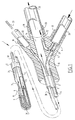
- Fig. 1 shows a partly broken away and cross-sectional view of a catheter according to a first embodiment of the invention.
- Fig. 2 shows a trifurcation of a catheter according to the invention in a preferred embodiment.
- the catheter 1 has a tube-like basic body 2 with a substantially circular cross-section. At the proximal end a trifurcation 15 has been formed, in which several channels, to be described later, are brought together. At the distal end an opening 7 has been formed in the basic body 2. This opening 7 forms a suction inlet which is connected with the lumen 3.
- a first separate tube-like body 4 has been received in the lumen 3 . It extends from the proximal end to the distal end.
- a channel 5 has been defined which comprises a bent back section 6 in the distal end and ends in a jet nozzle. Liquid under pressure, supplied via channel 5 can thus be directed as a liquid jet 8 along the opening 7, as a result of which a suction will be created indicated by arrow 9.
- the trifurcation 15 comprises a first branch 17 which forms an inlet for the pressure channel 5. Inside this branch 17 a tube section 20 has been fixed which is connected to a source of liquid under pressure.
- a second branch 18 of the trifurcation 15 forms the connection with the lumen 3 and functions as the discharge channel of the catheter.
- a tube section 25 is connected which can be connected to a collecting reservoir.
- the third branch 19 is also connected with a tube section 32 and forms a connection with a second separate tube-like body 30 inside the lumen 3.
- This tube-like body 30 forms a channel for a guide wire 33.
- the tube-like body 30 has been fed through as far as the distal end of the catheter 1 and has been received with its circumference sealed in the rounded front wall of the distal end.
- the guide wire 33 can extend over the entire length through the catheter and be pushed out of the front of the catheter at the opening 31. The catheter can thus be passed over the guide wire 33.
- a branch 21 of the pressure connection 20 has been received in the trifurcation 15.
- This branch 21 debouches into the discharge channel 24 with a spray nozzle 22 which is directed in the proximal direction.
- the liquid under pressure supplied via the pressure line 20 flows partly through the branch 21 and forms a liquid jet indicated with arrow 23 which, as seen in fig. 1, is aimed towards the right.
- a liquid jet pump is formed in the discharge channel 24 which creates additional suction in the channel 24.
- tubes 4 and 30 are different members which have been received substantially free in the basic body 2, they influence the bending performance of the basic body at the most to a very limited degree. Because of the symmetrical cross-section of the basic body 2 there is no preferred direction as far as bending is concerned so that the basic body is not sensitive to buckling.
- the catheter according to the invention can in a suitable manner be manufactured in such a way that the basic body 2 will be made up of a relatively bending-stiff proximal section and a relatively pliable distal section.
- Manufacturing such a catheter is relatively simple as the tube-like bodies 30 and 4 do not need to be interrupted. Only one weld needs to be made between the two tube-like sections making up the basic body 2.
- a catheter manufactured in this way has consequently a more pliable distal end-section as a result of which more tortuous blood vessels can be reached.
- trifurcation 40 has been attached by means of injection moulding to the basic body 2, in which the tube-like bodies 4 and 30 have already been received.
- the basic body 2, made up of the tube-like bodies 4 and 30, is placed in a suitably shaped mould and the protruding tube sections 4 and 30 are placed in the desired position.
- the required spaces, in particular those for forming the channel sections, are kept open by means of core pins which connect to the tube-like bodies and the basic body.
- a tube section 41 is also received in the mould and thus embedded in the trifurcation 40. This tube section 41 has the same function as the branch 21 in fig. 1.
- the tree-way furcation 40 has been manufactured in such a way that the discharge channel extends in a straight line to a branch 42.
- the pressure channel 5 and the guide wire channel in the tube-like body 30, are received in the branches 43 and 44 of the trifurcation 40 respectively, which extend laterally, parallel to each other at an oblique angle away from the discharge channel.
- the branch 44 in which the tube-like body 30 has been received is provided with a, as such known, haemostatic valve 45 at its free end. In this way a guide wire can be introduced and removed directly via the branch 44 of the trifurcation, without a need for any additional haemostatic provisions.
- the branch 42 of the discharge channel and the branch 43 of the pressure channel are both provided with male Luer-lock adapters 46 and 47 respectively. Consequently the suction catheter according to the invention provided with the trifurcation 40 has a very compact construction and is easy to handle.
Description
Claims (8)
- Suction catheter (1) comprising a tube-like basic body (2) with a distal and a proximal end, with a lumen (3) forming a discharge channel, and a pressure channel (5) formed in a separate tube-like body (4) received inside the lumen (3), wherein at the distal end the pressure channel is connected with a spray nozzle and the discharge channel with a suction inlet and at the proximal end the channels are connected to connecting members, characterized in that the basic body (2) in cross-section is substantially symmetrical with respect to a central point thereof over substantially the whole length thereof, wherein inside the lumen (3) of the basic body (2) a second separate tube-like body (30) has been received which forms a channel for a guide wire (33), which second tube-like body (30) at the distal end has been arranged with its circumference sealed in the wall of the basic body (2) and has been provided with an introduction member close to the proximal end.
- Catheter as claimed in claim 1, comprising a trifurcation (15) at the proximal end with one outlet at the distal side to which the basic body (2) has been connected and three separate outlets at the proximal side for the guide wire channel, the pressure channel (5) and the discharge channel respectively.
- Catheter as claimed in claim 2, wherein the outlet of the guide wire channel has been provided with a haemostatic valve (45).
- Catheter as claimed in claim 2 or 3, wherein the outlets of the pressure channel and the discharge channel are provided with Luer-lock adapters (46, 47).
- Catheter as claimed in claim 3 and 4, wherein the haemostatic valve (45) and the Luer-lock adapters (46, 47) have been integrated in the trifurcation.
- Catheter as claimed in one of the claims 2 - 5, wherein the trifurcation (40) has been manufactured in such a way that the discharge channel extends in a straight line and the guide wire channel and the pressure channel (5) extend laterally, parallel to each other at an oblique angle away from the discharge channel.
- Catheter as claimed in one of the claims 2 - 6, wherein a connecting channel (21) between the pressure channel (5) and the discharge channel (3) has been formed in the trifurcation (15) which debouches into the discharge channel (3) by means of a spray nozzle (22) directed in the proximal direction.
- Catheter as claimed in one of the previous claims, wherein the basic body (2) has been made up of a relatively stiff proximal section and a relatively pliable distal section, and the at least one separate tube-like member consists of one continuous unit.
Applications Claiming Priority (5)
| Application Number | Priority Date | Filing Date | Title |
|---|---|---|---|
| NL9401184A NL9401184A (en) | 1994-07-19 | 1994-07-19 | Suction catheter. |
| NL9401184 | 1994-07-19 | ||
| US08/504,203 US5713849A (en) | 1994-07-19 | 1995-07-19 | Suction catheter and method |
| CA002160408A CA2160408C (en) | 1994-07-19 | 1995-10-12 | Suction catheter |
| JP7267197A JPH09108332A (en) | 1994-07-19 | 1995-10-16 | Aspirating catheter |
Publications (2)
| Publication Number | Publication Date |
|---|---|
| EP0693295A1 EP0693295A1 (en) | 1996-01-24 |
| EP0693295B1 true EP0693295B1 (en) | 2002-09-25 |
Family
ID=27427257
Family Applications (1)
| Application Number | Title | Priority Date | Filing Date |
|---|---|---|---|
| EP95201873A Expired - Lifetime EP0693295B1 (en) | 1994-07-19 | 1995-07-07 | Suction catheter |
Country Status (5)
| Country | Link |
|---|---|
| US (1) | US5713849A (en) |
| EP (1) | EP0693295B1 (en) |
| JP (1) | JPH09108332A (en) |
| CA (1) | CA2160408C (en) |
| NL (1) | NL9401184A (en) |
Cited By (2)
| Publication number | Priority date | Publication date | Assignee | Title |
|---|---|---|---|---|
| US6511493B1 (en) | 2000-01-10 | 2003-01-28 | Hydrocision, Inc. | Liquid jet-powered surgical instruments |
| US9597107B2 (en) | 2002-10-25 | 2017-03-21 | Hydrocision, Inc. | Nozzle assemblies for liquid jet surgical instruments and surgical instruments employing the nozzle assemblies |
Families Citing this family (104)
| Publication number | Priority date | Publication date | Assignee | Title |
|---|---|---|---|---|
| US6676627B1 (en) * | 1990-08-06 | 2004-01-13 | Possis Medical, Inc. | Crossflow thrombectomy catheter and system |
| NL1003056C2 (en) * | 1996-05-07 | 1997-11-10 | Cordis Europ | Suction catheter with hemostasis device. |
| US6152909A (en) * | 1996-05-20 | 2000-11-28 | Percusurge, Inc. | Aspiration system and method |
| US6022336A (en) * | 1996-05-20 | 2000-02-08 | Percusurge, Inc. | Catheter system for emboli containment |
| NL1003226C2 (en) * | 1996-05-29 | 1997-12-03 | Cordis Europ | Suction catheter with preformed end section. |
| WO1998030275A1 (en) * | 1997-01-09 | 1998-07-16 | Harvest Technologies, Llc | Controller for delivery of fluids |
| US6849068B1 (en) | 1997-03-06 | 2005-02-01 | Medtronic Ave, Inc. | Aspiration catheter |
| US5968010A (en) * | 1997-04-30 | 1999-10-19 | Beth Israel Deaconess Medical Center, Inc. | Method for transvenously accessing the pericardial space via the right atrium |
| US20040215168A1 (en) * | 1997-04-30 | 2004-10-28 | Beth Israel Deaconess Medical Center | Kit for transvenously accessing the pericardial space via the right atrium |
| US6200303B1 (en) | 1997-04-30 | 2001-03-13 | Beth Israel Deaconess Medical Center, Inc. | Method and kit for transvenously accessing the pericardial space via the right atrium |
| FR2770409B1 (en) * | 1997-10-31 | 2000-06-23 | Soprane Sa | UNIVERSAL CATHETER |
| US6109259A (en) | 1997-12-10 | 2000-08-29 | Spirit Medical Systems, Inc. | Gas supplying and substance suctioning relative to a patients trachea |
| US7879022B2 (en) * | 1998-02-06 | 2011-02-01 | Medrad, Inc. | Rapid exchange fluid jet thrombectomy device and method |
| US9586023B2 (en) | 1998-02-06 | 2017-03-07 | Boston Scientific Limited | Direct stream hydrodynamic catheter system |
| US6755803B1 (en) * | 1998-02-06 | 2004-06-29 | Possis Medical, Inc. | Single operator exchange fluid jet thrombectomy device |
| US6875193B1 (en) * | 1998-02-06 | 2005-04-05 | Possis Medical, Inc. | Rapid exchange fluid jet thrombectomy device and method |
| US6156003A (en) * | 1998-05-12 | 2000-12-05 | Chase Medical, Inc. | Surgical visualization and moisturizing device |
| IL141014A0 (en) * | 1998-07-22 | 2002-02-10 | Angiolink Corp | Vascular suction cannula, dilator and surgical stapler |
| US6280415B1 (en) | 1999-03-10 | 2001-08-28 | W. Dudley Johnson | Tissue traction device |
| US7658735B2 (en) * | 1999-03-22 | 2010-02-09 | Spehalski Stephan R | Steerable wound drain device |
| US6375635B1 (en) | 1999-05-18 | 2002-04-23 | Hydrocision, Inc. | Fluid jet surgical instruments |
| EP1187549B1 (en) | 1999-05-26 | 2008-09-10 | Boston Scientific Limited | Sleeve for a medical endoscope |
| US6451017B1 (en) * | 2000-01-10 | 2002-09-17 | Hydrocision, Inc. | Surgical instruments with integrated electrocautery |
| US6719717B1 (en) * | 2000-03-17 | 2004-04-13 | Advanced Research & Technology Institute, Inc. | Thrombectomy treatment system and method |
| US6776770B1 (en) | 2000-09-07 | 2004-08-17 | Advanced Research & Technology Institute | Thromboaspiration valve-filter device and methods |
| US6893459B1 (en) | 2000-09-20 | 2005-05-17 | Ample Medical, Inc. | Heart valve annulus device and method of using same |
| US7691144B2 (en) | 2003-10-01 | 2010-04-06 | Mvrx, Inc. | Devices, systems, and methods for reshaping a heart valve annulus |
| US20080091264A1 (en) | 2002-11-26 | 2008-04-17 | Ample Medical, Inc. | Devices, systems, and methods for reshaping a heart valve annulus, including the use of magnetic tools |
| US8323228B2 (en) | 2007-04-12 | 2012-12-04 | Rex Medical L.P. | Dialysis catheter |
| US7097635B2 (en) * | 2001-01-09 | 2006-08-29 | Rex Medical, L.P. | Guidewire retrieval member for catheter insertion |
| US7077829B2 (en) | 2001-01-09 | 2006-07-18 | Rex Medical, L.P. | Dialysis catheter |
| US6986752B2 (en) * | 2001-01-09 | 2006-01-17 | Rex Medical, Lp | Peritoneal dialysis catheter and insertion method |
| US6814718B2 (en) * | 2001-01-09 | 2004-11-09 | Rex Medical, L.P | Dialysis catheter |
| US7011645B2 (en) | 2001-01-09 | 2006-03-14 | Rex Medical, L.P. | Dialysis catheter |
| EP1392394A4 (en) * | 2001-06-04 | 2005-05-18 | Albert Einstein Healthcare Network | Cardiac stimulating apparatus having a blood clot filter and atrial pacer |
| US20050021075A1 (en) * | 2002-12-30 | 2005-01-27 | Bonnette Michael J. | Guidewire having deployable sheathless protective filter |
| ES2290358T3 (en) | 2001-11-21 | 2008-02-16 | Hydrocision, Inc. | SURGICAL INSTRUMENTS WITH LIQUID SPLASH, WHICH INCLUDE CHANNEL OPENINGS ALONGED THROUGH THE SPLIT. |
| US6758836B2 (en) * | 2002-02-07 | 2004-07-06 | C. R. Bard, Inc. | Split tip dialysis catheter |
| US7179269B2 (en) * | 2002-05-20 | 2007-02-20 | Scimed Life Systems, Inc. | Apparatus and system for removing an obstruction from a lumen |
| US7241257B1 (en) * | 2002-06-28 | 2007-07-10 | Abbott Cardiovascular Systems, Inc. | Devices and methods to perform minimally invasive surgeries |
| US20040082859A1 (en) | 2002-07-01 | 2004-04-29 | Alan Schaer | Method and apparatus employing ultrasound energy to treat body sphincters |
| US10363061B2 (en) | 2002-10-25 | 2019-07-30 | Hydrocision, Inc. | Nozzle assemblies for liquid jet surgical instruments and surgical instruments for employing the nozzle assemblies |
| US7393339B2 (en) | 2003-02-21 | 2008-07-01 | C. R. Bard, Inc. | Multi-lumen catheter with separate distal tips |
| US20040181209A1 (en) * | 2003-03-14 | 2004-09-16 | Gross James R. | Multiple port catheter connector |
| US20040243095A1 (en) | 2003-05-27 | 2004-12-02 | Shekhar Nimkar | Methods and apparatus for inserting multi-lumen spit-tip catheters into a blood vessel |
| US20060129091A1 (en) | 2004-12-10 | 2006-06-15 | Possis Medical, Inc. | Enhanced cross stream mechanical thrombectomy catheter with backloading manifold |
| US20050004594A1 (en) * | 2003-07-02 | 2005-01-06 | Jeffrey Nool | Devices and methods for aspirating from filters |
| US8992454B2 (en) | 2004-06-09 | 2015-03-31 | Bard Access Systems, Inc. | Splitable tip catheter with bioresorbable adhesive |
| US20050279359A1 (en) * | 2004-06-17 | 2005-12-22 | Leblanc David M | Oral suction catheter |
| US7572244B2 (en) * | 2004-08-02 | 2009-08-11 | Medrad, Inc. | Miniature cross stream thrombectomy catheter |
| US9408964B2 (en) * | 2005-01-04 | 2016-08-09 | C. R. Bard, Inc. | Power injection catheters and method of injecting |
| US7931619B2 (en) * | 2005-01-04 | 2011-04-26 | C. R. Bard, Inc. | Power injection catheters |
| US20080188793A1 (en) * | 2007-02-06 | 2008-08-07 | Possis Medical, Inc. | Miniature flexible thrombectomy catheter |
| US8012117B2 (en) | 2007-02-06 | 2011-09-06 | Medrad, Inc. | Miniature flexible thrombectomy catheter |
| US8162878B2 (en) | 2005-12-05 | 2012-04-24 | Medrad, Inc. | Exhaust-pressure-operated balloon catheter system |
| US7846175B2 (en) * | 2006-04-03 | 2010-12-07 | Medrad, Inc. | Guidewire and collapsable filter system |
| US20080234722A1 (en) * | 2006-06-14 | 2008-09-25 | Possis Medical, Inc. | Inferior vena cava filter on guidewire |
| US7527058B2 (en) * | 2006-06-14 | 2009-05-05 | Medical Device Group, Inc. | Respiratory suction catheter assembly |
| CA2677343C (en) | 2007-02-05 | 2016-06-21 | Boston Scientific Limited | Thrombectomy apparatus and method |
| US8012141B2 (en) * | 2007-03-29 | 2011-09-06 | Wright Clifford A | Suction wand |
| US8974418B2 (en) * | 2007-06-12 | 2015-03-10 | Boston Scientific Limited | Forwardly directed fluid jet crossing catheter |
| US20080319386A1 (en) * | 2007-06-20 | 2008-12-25 | Possis Medical, Inc. | Forwardly directable fluid jet crossing catheter |
| CN101918066B (en) | 2007-10-17 | 2013-07-31 | 巴德阿克塞斯系统股份有限公司 | Manufacture of split tip catheters and the split tip catheters |
| US8066660B2 (en) | 2007-10-26 | 2011-11-29 | C. R. Bard, Inc. | Split-tip catheter including lateral distal openings |
| US8292841B2 (en) | 2007-10-26 | 2012-10-23 | C. R. Bard, Inc. | Solid-body catheter including lateral distal openings |
| US9579485B2 (en) | 2007-11-01 | 2017-02-28 | C. R. Bard, Inc. | Catheter assembly including a multi-lumen configuration |
| JP5452498B2 (en) | 2007-11-01 | 2014-03-26 | シー・アール・バード・インコーポレーテッド | Catheter assembly including triple lumen end |
| WO2009079539A1 (en) | 2007-12-17 | 2009-06-25 | Medrad, Inc. | Rheolytic thrombectomy catheter with self-inflation distal balloon |
| WO2009082669A1 (en) | 2007-12-26 | 2009-07-02 | Medrad, Inc. | Rheolytic thrombectomy catheter with self-inflating proximal balloon with drug infusion capabilities |
| DE112009000700T5 (en) | 2008-03-20 | 2011-02-10 | Medrad, Inc. | Hydrodynamic direct current catheter system |
| US9510854B2 (en) | 2008-10-13 | 2016-12-06 | Boston Scientific Scimed, Inc. | Thrombectomy catheter with control box having pressure/vacuum valve for synchronous aspiration and fluid irrigation |
| US8974445B2 (en) * | 2009-01-09 | 2015-03-10 | Recor Medical, Inc. | Methods and apparatus for treatment of cardiac valve insufficiency |
| US8468637B2 (en) | 2009-02-06 | 2013-06-25 | Endoclear Llc | Mechanically-actuated endotracheal tube cleaning device |
| WO2011126812A1 (en) | 2010-03-29 | 2011-10-13 | Endoclear, Llc | Airway cleaning and visualization |
| EP2393538B1 (en) | 2009-02-06 | 2017-10-18 | Endoclear LLC | Devices for cleaning endotracheal tubes |
| CA2779386C (en) | 2009-10-30 | 2018-09-11 | Sound Interventions, Inc. | Method and apparatus for treatment of hypertension through percutaneous ultrasound renal denervation |
| US8398579B2 (en) * | 2009-12-16 | 2013-03-19 | Medrad, Inc. | Catheter including composite guide and methods for use of the same |
| US8591450B2 (en) | 2010-06-07 | 2013-11-26 | Rex Medical L.P. | Dialysis catheter |
| US8986285B2 (en) * | 2011-03-14 | 2015-03-24 | Neuro Enterprises, Llc | Self-cleaning surgical suction device |
| WO2013063520A1 (en) | 2011-10-27 | 2013-05-02 | Endoclear, Llc | Endotracheal tube coupling adapters |
| US9597470B2 (en) * | 2012-02-06 | 2017-03-21 | Cook Medical Technologies Llc | Manifold having rotatable ports |
| US9332998B2 (en) | 2012-08-13 | 2016-05-10 | Covidien Lp | Apparatus and methods for clot disruption and evacuation |
| US9332999B2 (en) | 2012-08-13 | 2016-05-10 | Covidien Lp | Apparatus and methods for clot disruption and evacuation |
| WO2014089028A1 (en) | 2012-12-04 | 2014-06-12 | Endoclear Llc | Suction cleaning devices, systems and methods |
| USD748252S1 (en) | 2013-02-08 | 2016-01-26 | C. R. Bard, Inc. | Multi-lumen catheter tip |
| EP2968984B1 (en) | 2013-03-14 | 2016-08-17 | ReCor Medical, Inc. | Ultrasound-based neuromodulation system |
| WO2014159273A1 (en) | 2013-03-14 | 2014-10-02 | Recor Medical, Inc. | Methods of plating or coating ultrasound transducers |
| US9433427B2 (en) | 2014-04-08 | 2016-09-06 | Incuvate, Llc | Systems and methods for management of thrombosis |
| US9248221B2 (en) | 2014-04-08 | 2016-02-02 | Incuvate, Llc | Aspiration monitoring system and method |
| US9883877B2 (en) | 2014-05-19 | 2018-02-06 | Walk Vascular, Llc | Systems and methods for removal of blood and thrombotic material |
| WO2015187583A1 (en) | 2014-06-03 | 2015-12-10 | Endoclear Llc | Cleaning devices, systems and methods |
| WO2016011091A1 (en) | 2014-07-14 | 2016-01-21 | C. R. Bard, Inc. | Apparatuses, systems, and methods for inserting split tip catheters having enhanced stiffening and guiding features |
| US10702292B2 (en) | 2015-08-28 | 2020-07-07 | Incuvate, Llc | Aspiration monitoring system and method |
| US10561440B2 (en) | 2015-09-03 | 2020-02-18 | Vesatek, Llc | Systems and methods for manipulating medical devices |
| US20170100142A1 (en) | 2015-10-09 | 2017-04-13 | Incuvate, Llc | Systems and methods for management of thrombosis |
| CN113143539A (en) | 2015-12-10 | 2021-07-23 | 姆维亚克斯股份有限公司 | System for reshaping a heart valve annulus |
| US10226263B2 (en) | 2015-12-23 | 2019-03-12 | Incuvate, Llc | Aspiration monitoring system and method |
| US10492805B2 (en) | 2016-04-06 | 2019-12-03 | Walk Vascular, Llc | Systems and methods for thrombolysis and delivery of an agent |
| EP3500192A4 (en) | 2016-06-24 | 2020-05-13 | Hydrocision, Inc. | Selective tissue removal treatment device |
| US10492821B2 (en) | 2016-06-24 | 2019-12-03 | Hydrocision, Inc. | Selective tissue removal treatment device |
| US20180207397A1 (en) * | 2017-01-23 | 2018-07-26 | Walk Vascular, Llc | Systems and methods for removal of blood and thrombotic material |
| US11678905B2 (en) | 2018-07-19 | 2023-06-20 | Walk Vascular, Llc | Systems and methods for removal of blood and thrombotic material |
| US11446467B2 (en) * | 2018-09-25 | 2022-09-20 | Smiths Medical Asd, Inc. | Overmolded septum for catheter hub |
| EP3856318A4 (en) * | 2018-09-28 | 2022-06-15 | Flow Medical Corporation | Catheter apparatus |
Family Cites Families (15)
| Publication number | Priority date | Publication date | Assignee | Title |
|---|---|---|---|---|
| US4637814A (en) * | 1985-04-05 | 1987-01-20 | Arnold Leiboff | Method and apparatus for intestinal irrigation |
| US4715848A (en) * | 1985-04-15 | 1987-12-29 | Beroza Gregory A | Gastro-intestinal lavage system and method |
| FR2595252B1 (en) * | 1986-03-06 | 1988-07-08 | Imtec Sa | SURGICAL DRAIN |
| US5350395A (en) * | 1986-04-15 | 1994-09-27 | Yock Paul G | Angioplasty apparatus facilitating rapid exchanges |
| US4892519A (en) * | 1987-12-03 | 1990-01-09 | Advanced Cardiovascular Systems, Inc. | Steerable perfusion dilatation catheter |
| US5078688A (en) * | 1989-09-22 | 1992-01-07 | Baxter International Inc. | Paracentesis catheter system |
| DE69007465T2 (en) * | 1989-10-11 | 1994-10-20 | Baxter Int | INTEGRATED INTRACRANIAL PRESSURE MONITOR AND DRAINAGE CATHETER. |
| NL9000356A (en) * | 1990-02-14 | 1991-09-02 | Cordis Europ | DRAINAGE CATHETER. |
| US5496267A (en) * | 1990-11-08 | 1996-03-05 | Possis Medical, Inc. | Asymmetric water jet atherectomy |
| US5207648A (en) * | 1990-12-14 | 1993-05-04 | The Kendall Company | Multilumen catheter |
| US5261887A (en) * | 1992-01-22 | 1993-11-16 | Baxter International Inc. | Easy-to-handle, self-guiding catheter stripper |
| US5395352A (en) * | 1992-02-24 | 1995-03-07 | Scimed Lift Systems, Inc. | Y-adaptor manifold with pinch valve for an intravascular catheter |
| EP0586056B1 (en) * | 1992-07-07 | 1998-04-15 | William A. Cook Australia Pty. Ltd. | Medical coupling devices |
| US5300022A (en) * | 1992-11-12 | 1994-04-05 | Martin Klapper | Urinary catheter and bladder irrigation system |
| NL9300626A (en) * | 1993-04-13 | 1994-11-01 | Cordis Europ | Hydrodynamic suction catheter. |
-
1994
- 1994-07-19 NL NL9401184A patent/NL9401184A/en not_active Application Discontinuation
-
1995
- 1995-07-07 EP EP95201873A patent/EP0693295B1/en not_active Expired - Lifetime
- 1995-07-19 US US08/504,203 patent/US5713849A/en not_active Expired - Lifetime
- 1995-10-12 CA CA002160408A patent/CA2160408C/en not_active Expired - Lifetime
- 1995-10-16 JP JP7267197A patent/JPH09108332A/en active Pending
Cited By (3)
| Publication number | Priority date | Publication date | Assignee | Title |
|---|---|---|---|---|
| US6511493B1 (en) | 2000-01-10 | 2003-01-28 | Hydrocision, Inc. | Liquid jet-powered surgical instruments |
| US6669710B2 (en) | 2000-01-10 | 2003-12-30 | Hydrocision, Inc. | Liquid jet-powered surgical instruments |
| US9597107B2 (en) | 2002-10-25 | 2017-03-21 | Hydrocision, Inc. | Nozzle assemblies for liquid jet surgical instruments and surgical instruments employing the nozzle assemblies |
Also Published As
| Publication number | Publication date |
|---|---|
| JPH09108332A (en) | 1997-04-28 |
| NL9401184A (en) | 1996-03-01 |
| CA2160408A1 (en) | 1997-04-13 |
| US5713849A (en) | 1998-02-03 |
| EP0693295A1 (en) | 1996-01-24 |
| CA2160408C (en) | 2007-04-03 |
Similar Documents
| Publication | Publication Date | Title |
|---|---|---|
| EP0693295B1 (en) | Suction catheter | |
| US5453088A (en) | Hydrodynamic suction catheter | |
| CA2206015C (en) | Suction catheter with preformed tip | |
| EP0637453B1 (en) | Method for manufacturing a catheter with at least one high-pressure lumen and catheter | |
| CA2168009C (en) | Triple lumen catheter | |
| US5800414A (en) | Catheter with flexible and elongate body | |
| US7282041B2 (en) | Multi lumen catheter | |
| USRE41462E1 (en) | Bent co-axial catheter | |
| US5163431A (en) | Angiographic catheter | |
| EP1286709B1 (en) | Multi-lumen biliary catheter with angled guidewire exit | |
| CA2204562C (en) | Suction catheter with haemostatic device | |
| US6632315B2 (en) | Method of manufacturing a microdialysis catheter | |
| US5069673A (en) | Catheter with double step-down bore | |
| EP0707865A1 (en) | Catheter with guide wire channel | |
| WO1996041653A1 (en) | Catheter with an opening/closing mechanism | |
| US5372582A (en) | Probe for dialysis | |
| EP2035076B1 (en) | Device connector and a system comprising a medical device connector | |
| JP2022094560A (en) | Catheter connector | |
| CA2061163C (en) | Co-axial catheter | |
| JP2006314854A (en) | Suction catheter | |
| JPH04135570A (en) | Inserting tube |
Legal Events
| Date | Code | Title | Description |
|---|---|---|---|
| PUAI | Public reference made under article 153(3) epc to a published international application that has entered the european phase |
Free format text: ORIGINAL CODE: 0009012 |
|
| AK | Designated contracting states |
Kind code of ref document: A1 Designated state(s): AT BE CH DE DK ES FR GB IE IT LI NL PT SE |
|
| 17P | Request for examination filed |
Effective date: 19960711 |
|
| 17Q | First examination report despatched |
Effective date: 19990722 |
|
| GRAG | Despatch of communication of intention to grant |
Free format text: ORIGINAL CODE: EPIDOS AGRA |
|
| GRAG | Despatch of communication of intention to grant |
Free format text: ORIGINAL CODE: EPIDOS AGRA |
|
| GRAH | Despatch of communication of intention to grant a patent |
Free format text: ORIGINAL CODE: EPIDOS IGRA |
|
| GRAH | Despatch of communication of intention to grant a patent |
Free format text: ORIGINAL CODE: EPIDOS IGRA |
|
| GRAA | (expected) grant |
Free format text: ORIGINAL CODE: 0009210 |
|
| AK | Designated contracting states |
Kind code of ref document: B1 Designated state(s): AT BE CH DE DK ES FR GB IE IT LI NL PT SE |
|
| PG25 | Lapsed in a contracting state [announced via postgrant information from national office to epo] |
Ref country code: LI Free format text: LAPSE BECAUSE OF FAILURE TO SUBMIT A TRANSLATION OF THE DESCRIPTION OR TO PAY THE FEE WITHIN THE PRESCRIBED TIME-LIMIT Effective date: 20020925 Ref country code: IT Free format text: LAPSE BECAUSE OF FAILURE TO SUBMIT A TRANSLATION OF THE DESCRIPTION OR TO PAY THE FEE WITHIN THE PRESCRIBED TIME-LIMIT;WARNING: LAPSES OF ITALIAN PATENTS WITH EFFECTIVE DATE BEFORE 2007 MAY HAVE OCCURRED AT ANY TIME BEFORE 2007. THE CORRECT EFFECTIVE DATE MAY BE DIFFERENT FROM THE ONE RECORDED. Effective date: 20020925 Ref country code: FR Free format text: LAPSE BECAUSE OF FAILURE TO SUBMIT A TRANSLATION OF THE DESCRIPTION OR TO PAY THE FEE WITHIN THE PRESCRIBED TIME-LIMIT Effective date: 20020925 Ref country code: CH Free format text: LAPSE BECAUSE OF FAILURE TO SUBMIT A TRANSLATION OF THE DESCRIPTION OR TO PAY THE FEE WITHIN THE PRESCRIBED TIME-LIMIT Effective date: 20020925 Ref country code: AT Free format text: LAPSE BECAUSE OF FAILURE TO SUBMIT A TRANSLATION OF THE DESCRIPTION OR TO PAY THE FEE WITHIN THE PRESCRIBED TIME-LIMIT Effective date: 20020925 |
|
| REF | Corresponds to: |
Ref document number: 224743 Country of ref document: AT Date of ref document: 20021015 Kind code of ref document: T |
|
| REG | Reference to a national code |
Ref country code: GB Ref legal event code: FG4D |
|
| REG | Reference to a national code |
Ref country code: CH Ref legal event code: EP |
|
| REG | Reference to a national code |
Ref country code: IE Ref legal event code: FG4D |
|
| REF | Corresponds to: |
Ref document number: 69528321 Country of ref document: DE Date of ref document: 20021031 |
|
| PG25 | Lapsed in a contracting state [announced via postgrant information from national office to epo] |
Ref country code: SE Free format text: LAPSE BECAUSE OF FAILURE TO SUBMIT A TRANSLATION OF THE DESCRIPTION OR TO PAY THE FEE WITHIN THE PRESCRIBED TIME-LIMIT Effective date: 20021225 Ref country code: DK Free format text: LAPSE BECAUSE OF FAILURE TO SUBMIT A TRANSLATION OF THE DESCRIPTION OR TO PAY THE FEE WITHIN THE PRESCRIBED TIME-LIMIT Effective date: 20021225 |
|
| PG25 | Lapsed in a contracting state [announced via postgrant information from national office to epo] |
Ref country code: PT Free format text: LAPSE BECAUSE OF FAILURE TO SUBMIT A TRANSLATION OF THE DESCRIPTION OR TO PAY THE FEE WITHIN THE PRESCRIBED TIME-LIMIT Effective date: 20021226 |
|
| PG25 | Lapsed in a contracting state [announced via postgrant information from national office to epo] |
Ref country code: ES Free format text: LAPSE BECAUSE OF FAILURE TO SUBMIT A TRANSLATION OF THE DESCRIPTION OR TO PAY THE FEE WITHIN THE PRESCRIBED TIME-LIMIT Effective date: 20030328 |
|
| REG | Reference to a national code |
Ref country code: CH Ref legal event code: PL |
|
| EN | Fr: translation not filed | ||
| PLBE | No opposition filed within time limit |
Free format text: ORIGINAL CODE: 0009261 |
|
| STAA | Information on the status of an ep patent application or granted ep patent |
Free format text: STATUS: NO OPPOSITION FILED WITHIN TIME LIMIT |
|
| 26N | No opposition filed |
Effective date: 20030626 |
|
| PGFP | Annual fee paid to national office [announced via postgrant information from national office to epo] |
Ref country code: NL Payment date: 20140710 Year of fee payment: 20 Ref country code: DE Payment date: 20140702 Year of fee payment: 20 Ref country code: IE Payment date: 20140710 Year of fee payment: 20 |
|
| PGFP | Annual fee paid to national office [announced via postgrant information from national office to epo] |
Ref country code: GB Payment date: 20140702 Year of fee payment: 20 |
|
| PGFP | Annual fee paid to national office [announced via postgrant information from national office to epo] |
Ref country code: BE Payment date: 20140714 Year of fee payment: 20 |
|
| REG | Reference to a national code |
Ref country code: DE Ref legal event code: R071 Ref document number: 69528321 Country of ref document: DE |
|
| REG | Reference to a national code |
Ref country code: NL Ref legal event code: V4 Effective date: 20150707 |
|
| REG | Reference to a national code |
Ref country code: GB Ref legal event code: PE20 Expiry date: 20150706 |
|
| REG | Reference to a national code |
Ref country code: IE Ref legal event code: MK9A |
|
| PG25 | Lapsed in a contracting state [announced via postgrant information from national office to epo] |
Ref country code: GB Free format text: LAPSE BECAUSE OF EXPIRATION OF PROTECTION Effective date: 20150706 Ref country code: IE Free format text: LAPSE BECAUSE OF EXPIRATION OF PROTECTION Effective date: 20150707 |