EP0673233B1 - Ophthalmic lens removal apparatus - Google Patents
Ophthalmic lens removal apparatus Download PDFInfo
- Publication number
- EP0673233B1 EP0673233B1 EP94903346A EP94903346A EP0673233B1 EP 0673233 B1 EP0673233 B1 EP 0673233B1 EP 94903346 A EP94903346 A EP 94903346A EP 94903346 A EP94903346 A EP 94903346A EP 0673233 B1 EP0673233 B1 EP 0673233B1
- Authority
- EP
- European Patent Office
- Prior art keywords
- lens
- probe
- lens capsule
- rotary
- capsule
- Prior art date
- Legal status (The legal status is an assumption and is not a legal conclusion. Google has not performed a legal analysis and makes no representation as to the accuracy of the status listed.)
- Expired - Lifetime
Links
Images


Classifications
-
- A—HUMAN NECESSITIES
- A61—MEDICAL OR VETERINARY SCIENCE; HYGIENE
- A61F—FILTERS IMPLANTABLE INTO BLOOD VESSELS; PROSTHESES; DEVICES PROVIDING PATENCY TO, OR PREVENTING COLLAPSING OF, TUBULAR STRUCTURES OF THE BODY, e.g. STENTS; ORTHOPAEDIC, NURSING OR CONTRACEPTIVE DEVICES; FOMENTATION; TREATMENT OR PROTECTION OF EYES OR EARS; BANDAGES, DRESSINGS OR ABSORBENT PADS; FIRST-AID KITS
- A61F9/00—Methods or devices for treatment of the eyes; Devices for putting-in contact lenses; Devices to correct squinting; Apparatus to guide the blind; Protective devices for the eyes, carried on the body or in the hand
- A61F9/007—Methods or devices for eye surgery
- A61F9/00736—Instruments for removal of intra-ocular material or intra-ocular injection, e.g. cataract instruments
- A61F9/00763—Instruments for removal of intra-ocular material or intra-ocular injection, e.g. cataract instruments with rotating or reciprocating cutting elements, e.g. concentric cutting needles
-
- A—HUMAN NECESSITIES
- A61—MEDICAL OR VETERINARY SCIENCE; HYGIENE
- A61F—FILTERS IMPLANTABLE INTO BLOOD VESSELS; PROSTHESES; DEVICES PROVIDING PATENCY TO, OR PREVENTING COLLAPSING OF, TUBULAR STRUCTURES OF THE BODY, e.g. STENTS; ORTHOPAEDIC, NURSING OR CONTRACEPTIVE DEVICES; FOMENTATION; TREATMENT OR PROTECTION OF EYES OR EARS; BANDAGES, DRESSINGS OR ABSORBENT PADS; FIRST-AID KITS
- A61F9/00—Methods or devices for treatment of the eyes; Devices for putting-in contact lenses; Devices to correct squinting; Apparatus to guide the blind; Protective devices for the eyes, carried on the body or in the hand
-
- A—HUMAN NECESSITIES
- A61—MEDICAL OR VETERINARY SCIENCE; HYGIENE
- A61B—DIAGNOSIS; SURGERY; IDENTIFICATION
- A61B17/00—Surgical instruments, devices or methods, e.g. tourniquets
- A61B2017/00681—Aspects not otherwise provided for
- A61B2017/00685—Archimedes screw
Definitions
- This invention relates generally to an apparatus for removing ophthalmic lenses and more specifically for removing a cataractous ophthalmic lens for vision restoration.
- the lens of a human eye is a crystalline, transparent biconvex intraocular tissue that helps bring rays of light to focus on the retina.
- the lens is enclosed in a lens capsule and consists of lens cortex, and lens nucleus.
- the lens capsule is an elastic bag enveloping the lens and is suspended by fine ligaments (zonule) attached to the ciliary muscles. These muscles radially stretch and relax the capsule thereby varying the optical characteristics of the enclosed lens to provide the desired focus for an image. This is commonly referred to as accommodation.
- the lens cortex is a jelly-like portion of the crystalline lens, composed of a multiplicity of thin lens fibers that form the main body of the lens.
- the lens cortex is located between the denser inner nucleus and the elastic outer capsule.
- the lens nucleus is an optically defined-zone which is denser in the central position of the lens. This nucleus becomes even denser with age, eventually hardening and filling the entire lens. Additionally the lens may become opacified.
- This opacity and cloudiness of the crystalline lens or its surrounding transparent membrane may be congenital or may be caused by trauma, disease, or age.
- the cataractous lens obstructs the passage of light and tends to prevent the formation of a clear image on the retina.
- the cataract has become one of the most significant and common causes of ocular disability and blindness in our aging population. Cataract procedure is currently the most frequent surgery performed for a person over the age of 65. There were 4 million (U.S.: 1.6 million; foreign: 2.4 million) cataract surgeries performed in 1991, a number which is growing at an annual rate of 5%.
- the classic method of cataract surgery is the removal of the intact lens through a 7-10 mm incision and its replacement with an intraocular lens made from biocompatible polymers.
- This extracapsular cataract procedure restores vision but often causes post-operative complications resulting from the large incision, which include a prolonged healing process, increased trauma and astigmatism. Nevertheless, a majority of the current cataract procedures in the U.S. are performed using this intact extracapsular cataract removal technique.
- a 3 mm limbal incision is made about 45° to the iris plane allowing insertion of the instrument's tip into the anterior chamber in a direction almost parallel to the iris.
- the central part of the anterior capsule must be widely opened to facilitate emulsification of the lens nucleus and cortical clean-up, as well as to provide for an ideal intraocular lens placement in the sulcus of the posterior chamber.
- Phacoemulsification can be performed in the anterior chamber or posterior chamber of the eye.
- anterior chamber phacoemulsification the cataract lens is maneuvered into the anterior chamber where it is carved and removed from the chamber. This method is more traumatic to the endothelial layer of the cornea; however, it is an easier procedure for the surgeons to perform.
- Posterior chamber phacoemulsification consists of carving or shaving the central part of the lens while the lens is still in the capsule. This method is more difficult to perform due to the possibility of rupturing the posterior lens capsule and exposing the vitreous which fills the volume of the inner eyeball.
- the phacoemulsification technique provides the advantages of a smaller incision, a stronger post operative globe which reduces astigmatism, better wound closure, lower trauma and earlier improvement in vision.
- the phacoemulsification procedure is contraindicated for patients with dislocated cataract lens, a shallow anterior chamber, miotic pupils, low cornea-endothelial cell counts, or myope (a totally hard lens).
- the phacoemulsification technique also requires intense training in maneuvering the ultrasonic probe to carve the cataract lens nucleus. The energy can be destructive to the endothelial cells of the cornea ultimately resulting in complete degeneration. Due to these adverse circumstances, only about 45% of the U. S. surgeons currently prefer to use this phacoemulsification method over the conventional extracapsular method for cataract removal.
- US-3,976,077 discloses an ophthalmic surgical device including a rotary shaft with helical threads at one end, which terminate in a cutting tip for removing opacities on the surface of a lens in an eye.
- WO-A-92 11816 discloses a device for reducing the size of tissue contained within a sac-like anatomical structure.
- lens removal is accomplished with a rotary device which requires an incision of only about one to three millimeters. This small incision minimizes the trauma to the patient and increases the speed of recovery. With the small size of the incision, the postoperative complications are also minimized.
- a probe associated with the device includes a sheath which initially covers a rotatable tip during insertion of the probe. With the probe in place, this sheath can be retracted, exposing the rotary tip within the capsule. A saline solution can then be injected into the capsule facilitating separation of the lens from the walls of the capsule, a procedure commonly referred to as hydrodissection.
- the probe tip functions as a sharp impeller as it creates a flow of fluid within the capsule. This fluid flow draws the lens toward the probe tip where it is reduced in size for ultimate removal from the capsule.
- this configuration of the probe tip enables the procedure to function with the probe held substantially stationary within the capsule. There is no need for the surgeon to carefully manipulate the probe tip in order to perform the procedure, thus the potential risks associated with damaging the posterior lens capsule are avoided.
- lens reduction with the present invention is not limited by the hardness of the cataract lens, whereas cataract hardness limits the use of phacoemulsification apparatus of the prior art because of difficulty associated with carving out cataract lenses that are either too hard or too soft.
- the device may be used to achieve endocapsular cataract removal leaving both the anterior and posterior sides of the capsule intact. This is particularly desirable as it allows the possibility of injecting a fluid lens material substitute directly into the capsule. An injected elastomeric replacement material can benefit the patient with a potential for restoring accommodation capability. Furthermore, the endocapsular procedure avoids any risk associated with damaging the endothelial cell lining of the cornea.
- FIGS. 6 and 7 are included for illustrative purposes only and do not illustrate the device of the present invention.
- FIG. 1 An eye is illustrated in Figure 1 and designated generally by the reference numeral 10.
- the eye includes the sclera 12 and a cornea 14 which define an inner cavity of the eye 10.
- a limbus 15 provides a 1-2 mm wide transitional zone between the cornea 14 and the sclera 12.
- An iris 16 comprises a ring of pigmented tissue which lies behind the cornea 14.
- a central opening in the iris 16 is commonly referred to as a pupil 22.
- a lens structure 23 is supported by the sclera 12 and lies between the iris 16 and the vitreous 24, a transparent gelatinous mass which fills the interior of the eye 10 behind the lens structure 23.
- the interior of the eye 10 which lies between the cornea 14 and the vitreous 24 is divided into the two chambers, an anterior chamber 25 which lies between the cornea 14 and the plane of the iris 16, and a posterior chamber 26 which lies between the plane of the iris 16 and the vitreous 24.
- an image passes through the cornea 14 and the pupil 22 where the lens structure 23 functions to form a focused image onto a retina 27 at the back of the vitreous 24.
- Electrical impulses are generated by the retina 27 and carried by an optic nerve (not shown) to the brain.
- the lens structure 23 is of particular interest to the present invention.
- This structure includes a lens 41 which in its natural state is generally elastic and transparent.
- This lens 41 is enclosed in a lens capsule 43, the outer radius of which is supported by ciliary musculature 45.
- the ciliary musculature 45 responds to an image out of focus by radially stretching the lens capsule 43 or by relaxing the radial stretch on the lens capsule 43.
- This causes the enclosed lens 41 to vary its optical characteristics until the image is focused on the retina 27.
- the aging process degrades the elasticity of the material forming the lens 41 so that accommodation becomes impaired as this ability of the eye to reshape the lens 41 decreases.
- Another condition associated with aging is the clouding or reduced transparency of the crystalline material which forms the lens 41.
- cataracts form in this manner, blindness typically results increasing the desirability of removing the cataractous lens to restore vision.
- an apparatus for removing the lens 41 from the lens capsule 43 includes a control console 50 which houses a power supply and a motor controller that is operable by a foot pedal 52. Power from the control console 50 can be fed along a power cable 54 to a drive motor 56 which provides rotary power at a motor coupler 58.
- the motor controller in the console 50 can be adapted to provide for variations in speed as well as rotational direction. These characteristics of the rotary power controller can be programmed to provide desirable speed profiles, such as ramping, sine wave or square wave speed variation cycles.
- This rotary power is introduced from the drive motor 56 through a drive cable connector 61 and drive cable 62 to a handpiece 63 which includes a housing 64 and a probe 65.
- the probe 65 When operatively disposed as illustrated, the probe 65 extends through a small incision in the limbus 15 of the eye 10 and into the lens capsule 43.
- the drive cable connector 61 may also be adapted to receive input from an irrigation-aspiration apparatus 67 through a tube 68.
- control console 50, drive motor 56, foot pedal 52 and irrigation apparatus 67 will generally be reusable in a non-sterile state.
- the drive cable connector 61, drive cable 62, and handpiece 63 can either be disposable or adapted for limited reuse. In either case, these elements typically will be utilized in a sterile state.
- a key advantage of this embodiment of the invention is that it facilitates implementation of a handpiece 63 which is smaller in size, lighter in weight and significantly more maneuverable than the handpieces associated with the phacoemulsification apparatus of the prior art.
- the drive motor 56 is housed within and forms a portion of the control console 50.
- the power cable 54 is foreshortened and exists only within the control console 50 such that the drive motor 56 and motor coupler 58 are integral with the control console 50.
- FIG. 2 A further embodiment of the invention is illustrated in Figure 2 wherein the drive motor 56a forms a portion of the handpiece 63a.
- elements which are similar to those previously described are referred to with the same reference numeral followed by the lower case letter "a".
- the power cable 54a extends between the control console 50a and drive motor 56a.
- the drive motor 56a is included in the handpiece 63a so the rotary drive cable (not shown) is foreshortened and exists only within the handpiece 63a.
- the foot pedal 52 may be replaced with a finger switch 52a.
- the control console 50a will typically be reusable and will be utilized in a non-sterile state.
- the power cable 54a and motor drive 56a of the handpiece 63a may be adapted for limited reuse, but the distal end of the handpiece 63a, including the probe 65a, will typically be disposable.
- the power cable 54a, drive motor 56a, and probe 65a will be utilized in a sterile state.
- the handpiece 63 will typically have a length between 10 cm and 20 cm with the probe 65 accounting for about 1 cm to 4 cm of that length.
- the outside diameter of the handpiece is preferably between 7 mm and 15 mm while the probe 65 has a diameter between about 3 F (1 mm) and 9 F (3 mm).
- drive cable connector 61 Of particular interest to the present invention are the drive cable connector 61, drive cable 62 and handpiece 63. These elements are coupled to the drive motor 56 by inserting the drive cable connector 61 into the motor coupler 58 along an axis 69 as illustrated in Figure 3a.
- the drive motor 56 is located in an enclosure 70 having an inner bore 71 which extends through an annular projection forming the motor coupler 58.
- the drive motor 56 produces the rotary power which is provided to the motor coupler 58 on a rotary shaft 72.
- this shaft 72 is provided with an axial bore 74 which is slotted or otherwise shaped to a non-circular configuration.
- the motor coupler 58 is adapted to receive the drive cable connector 61 and to releasably lock the drive cable connector 61 in place, for example with a gate lock 81.
- the gate lock 81 includes a locking tab 83 which is slidably held in slots formed into the enclosure 70.
- the locking tab 83 is provided with an aperture 87 which is movable between a first position wherein the drive cable connector 61 can be inserted into or removed from the motor coupler 58, and a second position wherein the drive cable connector 61 is locked to the motor coupler 58.
- the locking tab 83 is provided with a thumb flange 90 which facilitates movement of the tab 83 between its first and second positions.
- the thumb flange 90 is also configured to compress a spring 92 against the enclosure 70. This spring 92 biases the flange 90 and locking tab 83 in the locking position as illustrated in Figure 3.
- a retaining pin 94 is fixed to the enclosure 70 and rides within a vertical slot 96 for limiting the distance of travel toward the locking position of the locking tab 83 when the drive cable connector 61 is absent.
- the drive cable connector 61 includes a housing 101 which forms a cylindrical male fitting 103 which is configured to register with the inner bore 71 of the enclosure 70.
- This fitting 103 has an inner bore 105 and an outwardly extending annular locking flange 107.
- a drive cable connector shaft 110 is supported in a ball bearing 112 and is configured to register with the non-circular bore 74 of the motor coupler 58.
- the locking tab 83 of the motor coupler 58 is initially depressed and the cylindrical fitting 103 is introduced through the aperture 87 into the inner bore 71 where the shaft 110 registers with the axial non-circular bore 74.
- the drive cable connector 61 is moved into the motor coupler 58 until the annular flange 107 engages a shoulder 114 on the enclosure 70.
- the locking tab 83 can be released permitting the spring 92 to move the tab to the locking position. This movement causes the aperture 87 to engage the flange 107 and lock the drive cable connector 61 to the motor coupler 58.
- the housing 101 of the drive cable connector 61 has walls which define an inwardly extending annular flange 121 and an inner cavity 123 which is tapered to an axial bore 125 at the distal end of the drive cable connector 61.
- the ball bearing 112 is located in the bore 105 and is held proximally of and against the flange 121 by a bearing retainer 126.
- the rotary motion imparted to the shaft 110 is transferred to a flexible shaft or cable 127 which is supported within a flexible tube 129 by a helical bearing 130.
- the flexible tube 129 has a lumen 132 with the same diameter as bore 125.
- the helical bearing 130 defines with the cable 127 and the flexible tube 129 a helical passage 133 which extends from the drive cable connector 61 to the handpiece 63.
- the elements 127-130 form the rotary drive cable 62.
- irrigate and/or aspirate the operative site In a particular procedure it may be desirable to irrigate and/or aspirate the operative site. This is accomplished in one embodiment by connecting the irrigation/aspiration apparatus 67 through the tubing 68 to the housing 101. In the illustrated embodiment, fluid from the apparatus 67 is introduced into the cavity 123 and is communicated through the helical passage 133 in the drive cable 62 to the handpiece 63 and the distal end of the probe 65.
- irrigation/aspiration fluid be isolated from the drive motor 56. This is accomplished in the illustrated embodiment by providing a high speed rotary face seal 134 which presses against and forms a fluid tight seal with a distally facing radial surface 136 of the annular flange 121.
- the seal 134 is of particular interest to the present invention as shown in greater detail in Figure 3b.
- the seal 134 is formed from an elastomeric material and includes an enlarged generally cylindrical ring 138 which is seated against the flange 139 in a fixed relationship with the shaft 110.
- This ring 138 is integral with a skirt 141 which has a generally conical configuration and extends proximally into contact with the surface 136.
- the skirt 141 is highly compliant and extends increasingly radially outwardly with progressive positions in the proximal direction.
- the elastomeric characteristics of the seal 134 bias the skirt 141 into sealing engagement with the surface 136 of the flange 121.
- the seal 134 functions as a high speed rotary seal, making it particularly advantageous for use in the lens removal system.
- centrifugal force causes the skirt 141 to flare radially outwardly. This causes the pressure of the seal 134 against the surface 136 to decrease with an increasing speed of rotation.
- a preferred embodiment of this seal is manufactured by Forsheda Shaft Seal Corporation and is referred to as a Forsheda V-ring seal.
- the proximal end of the handpiece 63 is provided with an elastomeric strain relief member 152 as illustrated in Figure 4.
- This member 152 is disposed around the drive cable 62 where it enters the housing 64 of the handpiece 63.
- the flexible tube 129 is terminated, but the drive cable 127 and helical bearing 130 continue through the housing 64 within a bore 154 with the same diameter as the lumen 132 of flexible tube 129.
- FIG. 5a A preferred embodiment of the distal end of the handpiece 63 is illustrated in Figure 5a.
- the probe 65 of the handpiece 63 is illustrated to include a cannula 161 which is fixed to the housing 64 and provides an extension of bore 154.
- the drive cable 127 and supporting helical bearing 130 and the helical fluid passage 133 extend into the cannula 161 to the distal end of the probe 65.
- the helical bearing 130 is terminated, and a rotary tip 163 is fixed to the drive cable 127 and supported by a bushing 165.
- the probe 65 is introduced into the lens capsule 43 with a needle structure. This is accomplished in the embodiment of Figure 5a by providing an outer sheath 170 which is slidable relative to the cannula 161 and movable between a distal position wherein the rotary tip 163 is covered (as illustrated in Figure 5a) and a proximal position wherein the rotary tip 163 is exposed (as illustrated in Figure 5b).
- the outer sheath 170 can be fixed to a nose cone 172 which is axially movable relative to the housing 64.
- the nose cone 172 includes a proximal bore 174 which registers with a cylindrical surface 176 which projects from the distal end of the housing 64.
- the nose cone 172 is configured to receive an O-ring 177 and associated retainer 178.
- the O-ring provides a seal between the cannula 161 and the sheath 170. This seal prevents air from entering the operative site and disrupting the induced fluid flow, for example, during aspiration or during activation of the rotary tip 163. This seal also prevents fluids from escaping from the operative site.
- the friction created between the nose cone 172 and cylindrical surface 176 as well as between the O-ring 177 and the cannula 161 may be sufficient to maintain the sheath 170 in either the forward or retracted position.
- the distal end of the protective sheath 170 is preferably sharpened to facilitate puncture of the lens capsule 43 and entry into lens the 41.
- Figure 6 illustrates the configuration of a cross bar which may be used in the present invention.
- a reducer 179 is supported on a shaft 180 which has an enlargement 181 at its proximal end. This enlargement 181 is fixed to the end of the drive cable 127 within the cannula 161 and proximally of the bushing 165. Distally of the bushing 165 a spacer 183 can be provided in fixed relationship with the shaft 180 to secure the rotary tip 163 at the distal end of the probe 65. Fluid is communicated to the operative site through the passage 133 and one or more axial slots 167 in the bushing 165.
- the cross bars used in the present invention are typically fixed at their center transversely to the shaft.
- a single cross bar 185 fixed in this manner is illustrated in Figure 7.
- the cross bar 185 On opposite sides of shaft 180, the cross bar 185 has opposing arms 186 and 187 which are pitched at an angle ⁇ (best illustrated in Figure 6) between 0 and 90°.
- ⁇ best illustrated in Figure 6
- the pitched arm 186 When the shaft 180 is rotated, for example in the direction of arrow 188 in Figure 6, the pitched arm 186 has a leading edge 189 and the pitched arm 187 has a leading edge 190.
- the cross bar 185 functions as an impeller (in the form of a pitched blade turbine) which in a generally confined fluid environment will create a fluid flow of particular interest to the present invention.
- Rotation of the impeller induces three-dimensional fluid flow with axial, radial and tangential components.
- the axial flow component is of particular interest because it is primarily the axial component which draws the object to be reduced into contact with the reducer 179.
- the best compromise to induce the axial inflow desired for the present invention is in a range of pitch angles ⁇ between 0° and 45°.
- the reducer 179 is provided with an axially extending member at each end of the cross bar 185.
- These axial members enhance the reducing action and are configured to be the first point of contact between the impeller and any object drawn into it by the fluid flow.
- the axial members designated by the reference numerals 191 and 192 in Figure 6 extend generally axially of the outer ends of the crossbar 185.
- the axial member 191 has a triangular configuration with a leading edge 193 which is disposed in a common axial plane with the leading edge 189.
- the axial member 192 can be similarly constructed but with a leading edge 194 which is shorter in axial length than the axial member 191.
- This axial member 192 has a triangular configuration which can be disposed in a common axial plane with the leading edge 190.
- the leading edges 189, 190, 193 and 194 are preferably sharpened to facilitate cutting or other reduction of the lens 41.
- the reducer 179 includes two cross members 185a and 185b which are disposed in generally perpendicular relationship on the shaft 180 as illustrated in Figure 8.
- the axial members 191a and 192a are disposed at opposite ends of the cross member 185a and are illustrated to be generally equal in axial dimension.
- a pair of axial members 191b and 192b are disposed at the ends of the cross member 185b and are also illustrated to be generally equal in axial dimension but shorter than the axial members 191a and 192a.
- the pitched arms 186, 186a, 186b, 187, 187a, and 187b preferably have radial lengths of two to six times the radius of the shaft 180.
- the longer axial members 191, 191a, and 192a have a preferred axial length about equal to the radial length of the pitched arms 186, 186a, 186b, 187, 187a, and 187b.
- the shorter axial members 192, 191b, and 192b preferably have an axial length of about one-half the axial length of the longer axial members 191, 191a, and 192a.
- the pitched arms 186 and 187 have a radial length of about 0.076cm (0.03 inches).
- the axial member 191 has an axial length of about 0.102 cm (0.04 inches) while the axial member 192 has an axial length of about 0.051 cm (0.02 inches).
- the pitched arms 186 and 187 and axial members 191 and 192 are preferably formed of hardened stainless steel having a thickness of about 0.013 cm (0.005 inches).
- the impellers may or may not be additionally modified to provide axially extending members to enhance the reducing action.
- Preferred embodiments of the reducer 179 are generally configured with four to six symmetrically or asymmetrically arranged pitched arms. Each of these pitched arms can either be radially oriented or inclined relative to the rotational axis.
- the present device is intended for reducing in size an object disposed in a generally confined fluid medium environment within a living mammalian body.
- a rotary member is inserted into the fluid medium where the axis of rotation and axial position of the rotary member is maintained generally stationary.
- the rotary member is rotated at a speed sufficient to reduce the object when the object is moved into the rotary member.
- the rotary member may be positioned into the fluid medium environment either by locating the rotary member at the distal end of a probe or by suspending the rotary member in a magnetic field.
- the device of the present invention is intended to be used in an environment wherein the probe 65 can be held generally stationary and a flow of fluid in the environment will bring material to the rotary tip 163 for reduction.
- This may be an environment where fluid flow already exists or it may be an environment which is sufficiently closed that the impeller action of the cross bar 185 will produce a generally continuous flow into the reducer 179. This flow will carry any object present in the environment into the reducer 179 for reduction in accordance with the present invention.
- the word "reducing" and derivatives thereof is deemed to include cutting, macerating, shearing, tearing, emulsifying, dissecting, fragmenting, and otherwise dividing objects within the environment.
- the reduction occurs when the object is in general contact with the reducer 179. This may include actual contact between the object and the reducer 179. However, it is also deemed to include those instances where there is no actual contact but sufficient proximity between the object and the reducer 179 for the desired reduction to occur.
- the sheath 170 described with reference to Figure 5 is moved to its forward or distal position covering the rotary tip 163 as shown in Figure 5a. In this position, the sharp distal end of the sheath 170 is exposed to facilitate introduction of the probe 65 through the anterior side of the lens capsule 43.
- a liquid 201 such as a saline solution, can be introduced through the probe 65 into the lens capsule 43. As the liquid 201 is introduced, the liquid will flow along the interior surfaces of the lens capsule 43 causing a separation of the lens capsule 43 from the lens 41.
- the method of separating the lens capsule from the lens by liquid injection is generally referred to as hydrodissection.
- This hydrodissection is of particular interest to the present invention as it initially functions to increase the mobility of the lens 41 within the lens capsule 43.
- the injected liquid 201 also facilitates disposition of lens 41 in a liquid environment within the lens capsule 43.
- introduction of liquid 201 can facilitate hydration and softening of the outer regions (lens cortex) of the lens 41.
- the flow of the liquid 201 is illustrated by the arrows 202 in Figure 9a.
- the sheath 170 can be returned to its proximal position as illustrated in Figure 5b either during or following the injection step. With the sheath 170 retracted, the rotary tip 163 is exposed.
- the control console 50 activates the drive motor 56 and imparts rotary motion through the drive cable 62 to the rotary tip 163.
- the reducer 179 begins to function as an impeller creating a fluid flow within the lens capsule 43.
- the lens 41 moves into contact with the rotary tip 163, it is rapidly reduced into very small pieces.
- the outer portions may be particularly soft in which case they will preferentially tend to liquify under the high speed reducing action. In this manner, the initial reducing of the lens 41 tends to increase the amount of liquid within the capsule 43 subsequently enhancing the mobility of the unreduced lens under the fluid action created by the rotary tip 163.
- the handpiece 63 and probe 65 can be held generally stationary within the lens capsule 43. There is no need to "search" with the probe 65 in order to reach the lens 41. Consequently, the likelihood of puncturing the lens capsule 43 by inadvertently over-extending the "reach" of the probe 65 is eliminated.
- This is a major advantage of the present invention over the prior art of phacoemulsification because a high degree of surgical skill and training is not required. Furthermore, the likelihood of tearing the lens capsule 43 at the point of probe entry as a result of probe manipulations, is greatly reduced.
- the probe can be held stationary while activation of the rotary tip 163 causes fluid flow as indicated by arrows 204 to move the unreduced portion of the lens 41 into the reducer 179.
- This movement of the unreduced lens 41 into the stationary probe 65 is illustrated by arrow 203 in Figure 9b.
- the axial inflow of fluid associated with this invention acts to draw into the probe 65 the unreduced portions of the lens 41, hereinafter designated by the reference numeral 241.
- the discharge of fluid from the reducer 179 reverses axial direction at a proximal end 210 of the lens capsule 43, flows along the lens capsule 43, and again reverses axial direction at a distal end 211 of the lens capsule 43, thus acting to push the unreduced portions of the lens 241 into the probe 65 as a result of the flow recirculation.
- rotation of the reducer 179 functions to create a fluid flow within a relatively confined environment which moves the object to be reduced into the rotating reducer 179.
- the lens 41 is completely reduced to small pieces as shown in Figure 9c.
- the pieces of reduced lens material are of sufficiently small in size to be easily removed from the intact lens capsule 43 by aspiration.
- the fluid and lens remnants within the capsule 43 can be aspirated through the probe 65 or through a separate probe (not shown) leaving the capsule 43 generally intact but absent the previously enclosed lens 41.
- the outer sheath 170 may provide a convenient means for aspiration of the fluid or may provide a means by which a separate probe can be introduced for aspiration.
- Figure 9c shows completion of lens reduction such that the remnants of lens are sufficiently reduced in size to allow for their removal from the intact lens capsule 43 by aspiration/irrigation.
- Methods practiced in the prior art commonly include implantation of a synthetic intraocular lens substitute, or to correct vision with glasses or contact lenses in the absence of an implanted lens substitute.
- a synthetic lens material can be injected into the lens capsule 43. This material fills the lens capsule 43 and essentially replaces the prior lens 41.
- An advantage of the endocapsular procedure is that the lens capsule 43 is left intact during the lens removal operation so that it can still function as an enclosure for the injected lens material.
- a synthetic lens material is to be introduced into the lens capsule 43, such injection can occur through the probe 65 or it can be accomplished by a separate probe (not shown). In either case, the procedure will not be complete until the probe 65 is removed from the lens capsule 43. This is accomplished by moving the sheath 170 to its distal position thereby covering the rotary tip 163 as illustrated in Figure 5a. In this configuration, the probe 65 can easily be retracted from the capsule 43 and the eye 10.
- the speed of rotation of the reducer 179 is of particular interest to the present invention since it not only provides the fluid flow but also produces the desired reduction of the lens 41.
- the most desirable speed will of course depend upon the size and configuration of the reducer 179, the volume and shape of the generally confined environment, the viscosity of the fluid, the magnitude of fluid flow desired, and of course the speed of reduction desired. Other factors might include the hardness of the object being reduced. Speeds in a range between 10,000 and 300,000 rpm seem to provide the best compromise of these factors. A preferred range of speed for the lens removal process is 30,000 to 100,000 rpm.
- the preferred embodiment includes the helical bearings 130 to support the cable 127 in the rotary drive cable 62.
- This bearing provides minimal contact with the cable 127 while at the same time providing support along its entire length.
- the helical bearing is formed by a wire having a circular cross section, the contact between the helical wire bearing 130 and the cable 127 is along a helical line which provides for minimal contact support from the drive cable connector 61, through the handpiece 63, to the distal end of the probe 65.
- the rotary member of the present invention need not be mechanically supported on the tip of a handpiece probe, but can be made of a magnetic material and suspended in the fluid environment by a magnetic field.
- the magnetic field can then be manipulated such that the rotary member remains generally laterally and axially stationary. Rotation of the rotary member on its rotational axis causes material within the fluid environment to be drawn by fluid flow to the rotary member where it is rapidly reduced.
- material within the fluid environment drawn to the tip of a handpiece probe need not be reduced by direct mechanical interaction with the rotary member.
- rotation of the rotary member on the tip of a handpiece probe can be used to induce a fluid flow that draws the material into proximity with the probe tip where a secondary energy source, such as laser, ultrasound, or electrohydraulic shock waves, can be utilized to effect reduction of the material.
Abstract
Description
- This invention relates generally to an apparatus for removing ophthalmic lenses and more specifically for removing a cataractous ophthalmic lens for vision restoration.
- The lens of a human eye is a crystalline, transparent biconvex intraocular tissue that helps bring rays of light to focus on the retina. The lens is enclosed in a lens capsule and consists of lens cortex, and lens nucleus. The lens capsule is an elastic bag enveloping the lens and is suspended by fine ligaments (zonule) attached to the ciliary muscles. These muscles radially stretch and relax the capsule thereby varying the optical characteristics of the enclosed lens to provide the desired focus for an image. This is commonly referred to as accommodation.
- The lens cortex is a jelly-like portion of the crystalline lens, composed of a multiplicity of thin lens fibers that form the main body of the lens. The lens cortex is located between the denser inner nucleus and the elastic outer capsule. The lens nucleus is an optically defined-zone which is denser in the central position of the lens. This nucleus becomes even denser with age, eventually hardening and filling the entire lens. Additionally the lens may become opacified.
- This opacity and cloudiness of the crystalline lens or its surrounding transparent membrane, commonly referred to as a cataract, may be congenital or may be caused by trauma, disease, or age. The cataractous lens obstructs the passage of light and tends to prevent the formation of a clear image on the retina.
- Surgery currently is the only method of restoring vision in a patient blinded by cataracts. The surgical removal of the opacified lens becomes necessary when visual loss due to cataract becomes significant. The lost optical power is restored by a contact lens, aphakic spectacle, or intraocular lens.
- The cataract has become one of the most significant and common causes of ocular disability and blindness in our aging population. Cataract procedure is currently the most frequent surgery performed for a person over the age of 65. There were 4 million (U.S.: 1.6 million; foreign: 2.4 million) cataract surgeries performed in 1991, a number which is growing at an annual rate of 5%.
- The classic method of cataract surgery is the removal of the intact lens through a 7-10 mm incision and its replacement with an intraocular lens made from biocompatible polymers. This extracapsular cataract procedure restores vision but often causes post-operative complications resulting from the large incision, which include a prolonged healing process, increased trauma and astigmatism. Nevertheless, a majority of the current cataract procedures in the U.S. are performed using this intact extracapsular cataract removal technique.
- More recently phacoemulsification devices, relying upon ultrasound, have been used for emulsifying the lens and removing it through a 3 millimeter incision in a shorter operative time. This technique provides easier rehabilitation and eliminates most of the post-operative complications resulting from the larger incision of conventional extracapsular cataract procedures.
- For the phacoemulslification procedure, a 3 mm limbal incision is made about 45° to the iris plane allowing insertion of the instrument's tip into the anterior chamber in a direction almost parallel to the iris. Once the limbal incision has been made, the central part of the anterior capsule must be widely opened to facilitate emulsification of the lens nucleus and cortical clean-up, as well as to provide for an ideal intraocular lens placement in the sulcus of the posterior chamber.
- Phacoemulsification can be performed in the anterior chamber or posterior chamber of the eye. In the case of anterior chamber phacoemulsification, the cataract lens is maneuvered into the anterior chamber where it is carved and removed from the chamber. This method is more traumatic to the endothelial layer of the cornea; however, it is an easier procedure for the surgeons to perform. Posterior chamber phacoemulsification consists of carving or shaving the central part of the lens while the lens is still in the capsule. This method is more difficult to perform due to the possibility of rupturing the posterior lens capsule and exposing the vitreous which fills the volume of the inner eyeball.
- The phacoemulsification technique provides the advantages of a smaller incision, a stronger post operative globe which reduces astigmatism, better wound closure, lower trauma and earlier improvement in vision. However, the phacoemulsification procedure is contraindicated for patients with dislocated cataract lens, a shallow anterior chamber, miotic pupils, low cornea-endothelial cell counts, or myope (a totally hard lens). The phacoemulsification technique also requires intense training in maneuvering the ultrasonic probe to carve the cataract lens nucleus. The energy can be destructive to the endothelial cells of the cornea ultimately resulting in complete degeneration. Due to these adverse circumstances, only about 45% of the U. S. surgeons currently prefer to use this phacoemulsification method over the conventional extracapsular method for cataract removal.
- Use of phacoemulsification devices to perform endocapsular cataract removal has also been investigated. In such a procedure, the cataractous lens must be carved away while both the anterior and posterior sides of the capsule are left intact. The extreme difficulty associated with this procedure has limited its adoption so that only about 1% of the U.S. cataract removal procedures are performed using this endocapsular technique.
- US-3,976,077 discloses an ophthalmic surgical device including a rotary shaft with helical threads at one end, which terminate in a cutting tip for removing opacities on the surface of a lens in an eye.
- WO-A-92 11816 discloses a device for reducing the size of tissue contained within a sac-like anatomical structure.
- Currently, there remains a need for apparatus that provide for safe and effective endocapsular lens removal, and associated methods which are less time consuming and skill intensive.
- According to the present invention, there is provided a device for reducing the size of an ophthalmic lens as claimed in claim 1.
- In accordance with the present invention, lens removal is accomplished with a rotary device which requires an incision of only about one to three millimeters. This small incision minimizes the trauma to the patient and increases the speed of recovery. With the small size of the incision, the postoperative complications are also minimized.
- A probe associated with the device includes a sheath which initially covers a rotatable tip during insertion of the probe. With the probe in place, this sheath can be retracted, exposing the rotary tip within the capsule. A saline solution can then be injected into the capsule facilitating separation of the lens from the walls of the capsule, a procedure commonly referred to as hydrodissection.
- The probe tip functions as a sharp impeller as it creates a flow of fluid within the capsule. This fluid flow draws the lens toward the probe tip where it is reduced in size for ultimate removal from the capsule. Importantly, this configuration of the probe tip enables the procedure to function with the probe held substantially stationary within the capsule. There is no need for the surgeon to carefully manipulate the probe tip in order to perform the procedure, thus the potential risks associated with damaging the posterior lens capsule are avoided. Furthermore, lens reduction with the present invention is not limited by the hardness of the cataract lens, whereas cataract hardness limits the use of phacoemulsification apparatus of the prior art because of difficulty associated with carving out cataract lenses that are either too hard or too soft.
- As the lens is reduced, the contents within the capsule become increasingly fludic and mobile, facilitating flow of the lens fragments into the rotating probe tip. Thus the ability of this device to draw unaffected lens material into the rotating tip increases as the procedure progresses. By merely placing the rotary tip probe in a single position within the capsule, rapid reduction of the contents of the capsule occurs without the need for tip position manipulations. The fragmented lens material is easily removed by subsequent use of a conventional irrigation-aspiration apparatus.
- The device may be used to achieve endocapsular cataract removal leaving both the anterior and posterior sides of the capsule intact. This is particularly desirable as it allows the possibility of injecting a fluid lens material substitute directly into the capsule. An injected elastomeric replacement material can benefit the patient with a potential for restoring accommodation capability. Furthermore, the endocapsular procedure avoids any risk associated with damaging the endothelial cell lining of the cornea.
- These and other features and advantages of the invention will be more apparent with the discussion of preferred embodiment and reference to the associated drawings.
- Figures 6 and 7 are included for illustrative purposes only and do not illustrate the device of the present invention.
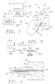
- Fig. 1 is a cross-sectional view of an eye with the probe, in one aspect of the invention, operatively disposed to fragment the lens of the eye;
- Fig. 2 is a side-elevation view of a further embodiment of the invention wherein a drive motor is configured as part of a handpiece;
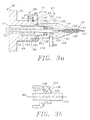
- Fig. 3a is an axial cross-section view of a coupling between a drive motor and a drive cable connector associated with the present invention;
- Fig. 3b is an enlarged axial cross-section view of a rotary seal associated with the drive cable connector;
- Fig. 4 is an axial cross-section view of a proximal end of the handpiece associated with the present invention;
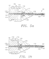
- Fig. 5a is an axial cross-section view of a sheath disposed in a distal position to cover a rotary tip of the handpiece;
- Fig. 5b is an axial cross-section view of the sheath disposed in a proximal position to expose the rotary tip;
- Fig. 6a is a side-elevation view of a probe tip having a single cross member of the type that may be used in the present invention;
- Fig. 6b is a front elevation view of the probe tip illustrated in Fig. 6a;
- Fig. 7 is a perspective view of the probe tip illustrated in Fig. 6a;
- Fig. 8 is a perspective view of a probe tip used in the present invention and having two cross members;
- Fig. 9a-9c is a series of axial cross-section views of the ocular lens and removal system, illustrating various steps in a method associated with the present invention;
- Fig. 9a illustrates a step for inserting the probe and injecting a liquid to effect hydrodissection;
- Fig. 9b illustrates a step for creating an enclosed fluid flow for moving the lens into the rotating tip of a stationary probe; and
- Fig. 9c illustrates an advanced step of lens fragmentation wherein the fluid flow is greatly increased and the lens is substantially fragmented for ultimate removal from the capsule.
-
- An eye is illustrated in Figure 1 and designated generally by the
reference numeral 10. The eye includes thesclera 12 and acornea 14 which define an inner cavity of theeye 10. Alimbus 15 provides a 1-2 mm wide transitional zone between thecornea 14 and thesclera 12. Aniris 16 comprises a ring of pigmented tissue which lies behind thecornea 14. A central opening in theiris 16 is commonly referred to as apupil 22. Alens structure 23 is supported by thesclera 12 and lies between theiris 16 and the vitreous 24, a transparent gelatinous mass which fills the interior of theeye 10 behind thelens structure 23. The interior of theeye 10 which lies between thecornea 14 and the vitreous 24 is divided into the two chambers, ananterior chamber 25 which lies between thecornea 14 and the plane of theiris 16, and aposterior chamber 26 which lies between the plane of theiris 16 and the vitreous 24. - When the
eye 10 is functioning normally, an image passes through thecornea 14 and thepupil 22 where thelens structure 23 functions to form a focused image onto aretina 27 at the back of the vitreous 24. Electrical impulses are generated by theretina 27 and carried by an optic nerve (not shown) to the brain. - The
lens structure 23 is of particular interest to the present invention. This structure includes alens 41 which in its natural state is generally elastic and transparent. Thislens 41 is enclosed in alens capsule 43, the outer radius of which is supported byciliary musculature 45. Under normal conditions, theciliary musculature 45 responds to an image out of focus by radially stretching thelens capsule 43 or by relaxing the radial stretch on thelens capsule 43. This causes theenclosed lens 41 to vary its optical characteristics until the image is focused on theretina 27. Unfortunately, the aging process degrades the elasticity of the material forming thelens 41 so that accommodation becomes impaired as this ability of the eye to reshape thelens 41 decreases. - Another condition associated with aging is the clouding or reduced transparency of the crystalline material which forms the
lens 41. When cataracts form in this manner, blindness typically results increasing the desirability of removing the cataractous lens to restore vision. - In one embodiment of the present invention, an apparatus for removing the
lens 41 from thelens capsule 43 includes acontrol console 50 which houses a power supply and a motor controller that is operable by afoot pedal 52. Power from thecontrol console 50 can be fed along apower cable 54 to adrive motor 56 which provides rotary power at amotor coupler 58. The motor controller in theconsole 50 can be adapted to provide for variations in speed as well as rotational direction. These characteristics of the rotary power controller can be programmed to provide desirable speed profiles, such as ramping, sine wave or square wave speed variation cycles. - This rotary power is introduced from the
drive motor 56 through adrive cable connector 61 and drivecable 62 to ahandpiece 63 which includes ahousing 64 and aprobe 65. When operatively disposed as illustrated, theprobe 65 extends through a small incision in thelimbus 15 of theeye 10 and into thelens capsule 43. Thedrive cable connector 61 may also be adapted to receive input from an irrigation-aspiration apparatus 67 through atube 68. - In this particular embodiment of Figure 1, the
control console 50, drivemotor 56,foot pedal 52 andirrigation apparatus 67 will generally be reusable in a non-sterile state. Thedrive cable connector 61, drivecable 62, andhandpiece 63 can either be disposable or adapted for limited reuse. In either case, these elements typically will be utilized in a sterile state. Certainly a key advantage of this embodiment of the invention is that it facilitates implementation of ahandpiece 63 which is smaller in size, lighter in weight and significantly more maneuverable than the handpieces associated with the phacoemulsification apparatus of the prior art. - In a further embodiment of the invention, the
drive motor 56 is housed within and forms a portion of thecontrol console 50. In this embodiment, thepower cable 54 is foreshortened and exists only within thecontrol console 50 such that thedrive motor 56 andmotor coupler 58 are integral with thecontrol console 50. - A further embodiment of the invention is illustrated in Figure 2 wherein the
drive motor 56a forms a portion of thehandpiece 63a. In this embodiment elements which are similar to those previously described are referred to with the same reference numeral followed by the lower case letter "a". - In the Figure 2 embodiment, the
power cable 54a extends between thecontrol console 50a and drivemotor 56a. In this case, however, thedrive motor 56a is included in thehandpiece 63a so the rotary drive cable (not shown) is foreshortened and exists only within thehandpiece 63a. Thefoot pedal 52 may be replaced with afinger switch 52a. In this particular embodiment, thecontrol console 50a will typically be reusable and will be utilized in a non-sterile state. Thepower cable 54a andmotor drive 56a of thehandpiece 63a may be adapted for limited reuse, but the distal end of thehandpiece 63a, including theprobe 65a, will typically be disposable. In this embodiment, thepower cable 54a, drivemotor 56a, andprobe 65a will be utilized in a sterile state. - In either of the foregoing embodiments, the
handpiece 63 will typically have a length between 10 cm and 20 cm with theprobe 65 accounting for about 1 cm to 4 cm of that length. The outside diameter of the handpiece is preferably between 7 mm and 15 mm while theprobe 65 has a diameter between about 3 F (1 mm) and 9 F (3 mm). - Of particular interest to the present invention are the
drive cable connector 61, drivecable 62 andhandpiece 63. These elements are coupled to thedrive motor 56 by inserting thedrive cable connector 61 into themotor coupler 58 along anaxis 69 as illustrated in Figure 3a. - In this particular embodiment, the
drive motor 56 is located in anenclosure 70 having aninner bore 71 which extends through an annular projection forming themotor coupler 58. Thedrive motor 56 produces the rotary power which is provided to themotor coupler 58 on arotary shaft 72. In order to provide a means for axial shaft engagement, thisshaft 72 is provided with anaxial bore 74 which is slotted or otherwise shaped to a non-circular configuration. - The
motor coupler 58 is adapted to receive thedrive cable connector 61 and to releasably lock thedrive cable connector 61 in place, for example with agate lock 81. In the illustrated embodiment thegate lock 81 includes alocking tab 83 which is slidably held in slots formed into theenclosure 70. Thelocking tab 83 is provided with anaperture 87 which is movable between a first position wherein thedrive cable connector 61 can be inserted into or removed from themotor coupler 58, and a second position wherein thedrive cable connector 61 is locked to themotor coupler 58. Thelocking tab 83 is provided with athumb flange 90 which facilitates movement of thetab 83 between its first and second positions. Thethumb flange 90 is also configured to compress aspring 92 against theenclosure 70. Thisspring 92 biases theflange 90 andlocking tab 83 in the locking position as illustrated in Figure 3. A retainingpin 94 is fixed to theenclosure 70 and rides within avertical slot 96 for limiting the distance of travel toward the locking position of thelocking tab 83 when thedrive cable connector 61 is absent. - The
drive cable connector 61 includes ahousing 101 which forms a cylindrical male fitting 103 which is configured to register with theinner bore 71 of theenclosure 70. This fitting 103 has aninner bore 105 and an outwardly extendingannular locking flange 107. A drivecable connector shaft 110 is supported in aball bearing 112 and is configured to register with the non-circular bore 74 of themotor coupler 58. - In operation, the
locking tab 83 of themotor coupler 58 is initially depressed and thecylindrical fitting 103 is introduced through theaperture 87 into theinner bore 71 where theshaft 110 registers with the axial non-circular bore 74. Thedrive cable connector 61 is moved into themotor coupler 58 until theannular flange 107 engages ashoulder 114 on theenclosure 70. At this point the lockingtab 83 can be released permitting thespring 92 to move the tab to the locking position. This movement causes theaperture 87 to engage theflange 107 and lock thedrive cable connector 61 to themotor coupler 58. - The
housing 101 of thedrive cable connector 61 has walls which define an inwardly extendingannular flange 121 and aninner cavity 123 which is tapered to anaxial bore 125 at the distal end of thedrive cable connector 61. Theball bearing 112 is located in thebore 105 and is held proximally of and against theflange 121 by a bearingretainer 126. - At the distal end of the
drive cable connector 61 the rotary motion imparted to theshaft 110 is transferred to a flexible shaft orcable 127 which is supported within aflexible tube 129 by ahelical bearing 130. In this embodiment, theflexible tube 129 has alumen 132 with the same diameter asbore 125. Thehelical bearing 130 defines with thecable 127 and the flexible tube 129 ahelical passage 133 which extends from thedrive cable connector 61 to thehandpiece 63. The elements 127-130 form therotary drive cable 62. - In a particular procedure it may be desirable to irrigate and/or aspirate the operative site. This is accomplished in one embodiment by connecting the irrigation/
aspiration apparatus 67 through thetubing 68 to thehousing 101. In the illustrated embodiment, fluid from theapparatus 67 is introduced into thecavity 123 and is communicated through thehelical passage 133 in thedrive cable 62 to thehandpiece 63 and the distal end of theprobe 65. - It is particularly desirable that the irrigation/aspiration fluid be isolated from the
drive motor 56. This is accomplished in the illustrated embodiment by providing a high speedrotary face seal 134 which presses against and forms a fluid tight seal with a distally facingradial surface 136 of theannular flange 121. - The
seal 134 is of particular interest to the present invention as shown in greater detail in Figure 3b. In this embodiment, theseal 134 is formed from an elastomeric material and includes an enlarged generallycylindrical ring 138 which is seated against theflange 139 in a fixed relationship with theshaft 110. Thisring 138 is integral with askirt 141 which has a generally conical configuration and extends proximally into contact with thesurface 136. Theskirt 141 is highly compliant and extends increasingly radially outwardly with progressive positions in the proximal direction. The elastomeric characteristics of theseal 134 bias theskirt 141 into sealing engagement with thesurface 136 of theflange 121. - With this configuration and orientation, the
seal 134 functions as a high speed rotary seal, making it particularly advantageous for use in the lens removal system. With increasing speed of rotation, centrifugal force causes theskirt 141 to flare radially outwardly. This causes the pressure of theseal 134 against thesurface 136 to decrease with an increasing speed of rotation. These characteristics of theseal 134 also reduce the frictional forces which might generate heat and otherwise impede high rotational speeds. A preferred embodiment of this seal is manufactured by Forsheda Shaft Seal Corporation and is referred to as a Forsheda V-ring seal. - At the opposite end of the
rotary drive cable 62, the proximal end of thehandpiece 63 is provided with an elastomericstrain relief member 152 as illustrated in Figure 4. Thismember 152 is disposed around thedrive cable 62 where it enters thehousing 64 of thehandpiece 63. Within thehousing 64, theflexible tube 129 is terminated, but thedrive cable 127 andhelical bearing 130 continue through thehousing 64 within abore 154 with the same diameter as thelumen 132 offlexible tube 129. - A preferred embodiment of the distal end of the
handpiece 63 is illustrated in Figure 5a. In this view, theprobe 65 of thehandpiece 63 is illustrated to include acannula 161 which is fixed to thehousing 64 and provides an extension ofbore 154. Thedrive cable 127 and supportinghelical bearing 130 and thehelical fluid passage 133 extend into thecannula 161 to the distal end of theprobe 65. In this distal location, thehelical bearing 130 is terminated, and arotary tip 163 is fixed to thedrive cable 127 and supported by abushing 165. - In a preferred method of using the device according to the invention the
probe 65 is introduced into thelens capsule 43 with a needle structure. This is accomplished in the embodiment of Figure 5a by providing anouter sheath 170 which is slidable relative to thecannula 161 and movable between a distal position wherein therotary tip 163 is covered (as illustrated in Figure 5a) and a proximal position wherein therotary tip 163 is exposed (as illustrated in Figure 5b). - The
outer sheath 170 can be fixed to anose cone 172 which is axially movable relative to thehousing 64. In a preferred embodiment, thenose cone 172 includes aproximal bore 174 which registers with acylindrical surface 176 which projects from the distal end of thehousing 64. Thenose cone 172 is configured to receive an O-ring 177 and associatedretainer 178. The O-ring provides a seal between thecannula 161 and thesheath 170. This seal prevents air from entering the operative site and disrupting the induced fluid flow, for example, during aspiration or during activation of therotary tip 163. This seal also prevents fluids from escaping from the operative site. The friction created between thenose cone 172 andcylindrical surface 176 as well as between the O-ring 177 and thecannula 161 may be sufficient to maintain thesheath 170 in either the forward or retracted position. In an embodiment including thenose cone 172, the distal end of theprotective sheath 170 is preferably sharpened to facilitate puncture of thelens capsule 43 and entry into lens the 41. - Figure 6 illustrates the configuration of a cross bar which may be used in the present invention. A
reducer 179 is supported on ashaft 180 which has anenlargement 181 at its proximal end. Thisenlargement 181 is fixed to the end of thedrive cable 127 within thecannula 161 and proximally of thebushing 165. Distally of the bushing 165 aspacer 183 can be provided in fixed relationship with theshaft 180 to secure therotary tip 163 at the distal end of theprobe 65. Fluid is communicated to the operative site through thepassage 133 and one or moreaxial slots 167 in thebushing 165. - The cross bars used in the present invention are typically fixed at their center transversely to the shaft. A
single cross bar 185 fixed in this manner is illustrated in Figure 7. On opposite sides ofshaft 180, thecross bar 185 has opposingarms shaft 180 is rotated, for example in the direction ofarrow 188 in Figure 6, the pitchedarm 186 has aleading edge 189 and the pitchedarm 187 has aleading edge 190. - With this configuration and orientation, the
cross bar 185 functions as an impeller (in the form of a pitched blade turbine) which in a generally confined fluid environment will create a fluid flow of particular interest to the present invention. Rotation of the impeller induces three-dimensional fluid flow with axial, radial and tangential components. In the present invention, the axial flow component is of particular interest because it is primarily the axial component which draws the object to be reduced into contact with thereducer 179. The best compromise to induce the axial inflow desired for the present invention is in a range of pitch angles Θ between 0° and 45°. - The
reducer 179 is provided with an axially extending member at each end of thecross bar 185. These axial members enhance the reducing action and are configured to be the first point of contact between the impeller and any object drawn into it by the fluid flow. The axial members, designated by thereference numerals crossbar 185. Theaxial member 191 has a triangular configuration with aleading edge 193 which is disposed in a common axial plane with theleading edge 189. Theaxial member 192 can be similarly constructed but with aleading edge 194 which is shorter in axial length than theaxial member 191. Thisaxial member 192 has a triangular configuration which can be disposed in a common axial plane with theleading edge 190. The leadingedges lens 41. - In the present invention, the
reducer 179 includes twocross members 185a and 185b which are disposed in generally perpendicular relationship on theshaft 180 as illustrated in Figure 8. Theaxial members 191a and 192a are disposed at opposite ends of thecross member 185a and are illustrated to be generally equal in axial dimension. A pair of axial members 191b and 192b are disposed at the ends of the cross member 185b and are also illustrated to be generally equal in axial dimension but shorter than theaxial members 191a and 192a. - In order to achieve the desired fluid flow and speed of reduction, the pitched
arms shaft 180. The longeraxial members arms axial members 192, 191b, and 192b preferably have an axial length of about one-half the axial length of the longeraxial members shaft 180 has a diameter of about 0.038 cm (0.015 inches), the pitchedarms axial member 191 has an axial length of about 0.102 cm (0.04 inches) while theaxial member 192 has an axial length of about 0.051 cm (0.02 inches). The pitchedarms axial members - The impellers may or may not be additionally modified to provide axially extending members to enhance the reducing action. Preferred embodiments of the
reducer 179 are generally configured with four to six symmetrically or asymmetrically arranged pitched arms. Each of these pitched arms can either be radially oriented or inclined relative to the rotational axis. - The present device is intended for reducing in size an object disposed in a generally confined fluid medium environment within a living mammalian body. A rotary member is inserted into the fluid medium where the axis of rotation and axial position of the rotary member is maintained generally stationary. The rotary member is rotated at a speed sufficient to reduce the object when the object is moved into the rotary member. The rotary member may be positioned into the fluid medium environment either by locating the rotary member at the distal end of a probe or by suspending the rotary member in a magnetic field.
- The device of the present invention is intended to be used in an environment wherein the
probe 65 can be held generally stationary and a flow of fluid in the environment will bring material to therotary tip 163 for reduction. This may be an environment where fluid flow already exists or it may be an environment which is sufficiently closed that the impeller action of thecross bar 185 will produce a generally continuous flow into thereducer 179. This flow will carry any object present in the environment into thereducer 179 for reduction in accordance with the present invention. - As used herein, the word "reducing" and derivatives thereof is deemed to include cutting, macerating, shearing, tearing, emulsifying, dissecting, fragmenting, and otherwise dividing objects within the environment. The reduction occurs when the object is in general contact with the
reducer 179. This may include actual contact between the object and thereducer 179. However, it is also deemed to include those instances where there is no actual contact but sufficient proximity between the object and thereducer 179 for the desired reduction to occur. - The apparatus previously discussed is particularly useful for removing the
lens 41 from thelens capsule 43. Initially, thesheath 170 described with reference to Figure 5 is moved to its forward or distal position covering therotary tip 163 as shown in Figure 5a. In this position, the sharp distal end of thesheath 170 is exposed to facilitate introduction of theprobe 65 through the anterior side of thelens capsule 43. With theprobe 65 in this position, as illustrated in Figure 9a, a liquid 201, such as a saline solution, can be introduced through theprobe 65 into thelens capsule 43. As the liquid 201 is introduced, the liquid will flow along the interior surfaces of thelens capsule 43 causing a separation of thelens capsule 43 from thelens 41. The method of separating the lens capsule from the lens by liquid injection is generally referred to as hydrodissection. - This hydrodissection is of particular interest to the present invention as it initially functions to increase the mobility of the
lens 41 within thelens capsule 43. The injected liquid 201 also facilitates disposition oflens 41 in a liquid environment within thelens capsule 43. In addition, introduction ofliquid 201 can facilitate hydration and softening of the outer regions (lens cortex) of thelens 41. The flow of the liquid 201 is illustrated by thearrows 202 in Figure 9a. - The
sheath 170 can be returned to its proximal position as illustrated in Figure 5b either during or following the injection step. With thesheath 170 retracted, therotary tip 163 is exposed. - As the
foot pedal 52 is depressed, thecontrol console 50 activates thedrive motor 56 and imparts rotary motion through thedrive cable 62 to therotary tip 163. As therotary tip 163 rotates, thereducer 179 begins to function as an impeller creating a fluid flow within thelens capsule 43. As thelens 41 moves into contact with therotary tip 163, it is rapidly reduced into very small pieces. In the case of thelens 41, the outer portions may be particularly soft in which case they will preferentially tend to liquify under the high speed reducing action. In this manner, the initial reducing of thelens 41 tends to increase the amount of liquid within thecapsule 43 subsequently enhancing the mobility of the unreduced lens under the fluid action created by therotary tip 163. - Of particular importance to the present invention is the fact that the
handpiece 63 and probe 65 can be held generally stationary within thelens capsule 43. There is no need to "search" with theprobe 65 in order to reach thelens 41. Consequently, the likelihood of puncturing thelens capsule 43 by inadvertently over-extending the "reach" of theprobe 65 is eliminated. This is a major advantage of the present invention over the prior art of phacoemulsification because a high degree of surgical skill and training is not required. Furthermore, the likelihood of tearing thelens capsule 43 at the point of probe entry as a result of probe manipulations, is greatly reduced. - As illustrated in Figure 9b the probe can be held stationary while activation of the
rotary tip 163 causes fluid flow as indicated byarrows 204 to move the unreduced portion of thelens 41 into thereducer 179. This movement of theunreduced lens 41 into thestationary probe 65 is illustrated byarrow 203 in Figure 9b. As reduction of thelens 41 increases, the contents of thecapsule 43 become increasingly fluidic and mobile. The axial inflow of fluid associated with this invention acts to draw into theprobe 65 the unreduced portions of thelens 41, hereinafter designated by thereference numeral 241. In addition, the discharge of fluid from thereducer 179 reverses axial direction at aproximal end 210 of thelens capsule 43, flows along thelens capsule 43, and again reverses axial direction at adistal end 211 of thelens capsule 43, thus acting to push the unreduced portions of thelens 241 into theprobe 65 as a result of the flow recirculation. Thus rotation of thereducer 179 functions to create a fluid flow within a relatively confined environment which moves the object to be reduced into therotating reducer 179. - As reduction progresses, the
lens 41 is completely reduced to small pieces as shown in Figure 9c. The pieces of reduced lens material are of sufficiently small in size to be easily removed from theintact lens capsule 43 by aspiration. During the reduction process, it may be desirable to alter the fluidic properties within the confined environment by adding a second fluid or by exchanging the existing fluid with the second fluid. - As reduction progresses, or after it has been completed, the fluid and lens remnants within the
capsule 43 can be aspirated through theprobe 65 or through a separate probe (not shown) leaving thecapsule 43 generally intact but absent the previously enclosedlens 41. In another embodiment, by retracting all inner workings from theouter sheath 170 ofprobe 65, theouter sheath 170 may provide a convenient means for aspiration of the fluid or may provide a means by which a separate probe can be introduced for aspiration. Figure 9c shows completion of lens reduction such that the remnants of lens are sufficiently reduced in size to allow for their removal from theintact lens capsule 43 by aspiration/irrigation. - At this point, the steps associated with replacing a lens may differ considerably. Methods practiced in the prior art commonly include implantation of a synthetic intraocular lens substitute, or to correct vision with glasses or contact lenses in the absence of an implanted lens substitute. Also, a synthetic lens material can be injected into the
lens capsule 43. This material fills thelens capsule 43 and essentially replaces theprior lens 41. An advantage of the endocapsular procedure is that thelens capsule 43 is left intact during the lens removal operation so that it can still function as an enclosure for the injected lens material. - If a synthetic lens material is to be introduced into the
lens capsule 43, such injection can occur through theprobe 65 or it can be accomplished by a separate probe (not shown). In either case, the procedure will not be complete until theprobe 65 is removed from thelens capsule 43. This is accomplished by moving thesheath 170 to its distal position thereby covering therotary tip 163 as illustrated in Figure 5a. In this configuration, theprobe 65 can easily be retracted from thecapsule 43 and theeye 10. - The speed of rotation of the
reducer 179 is of particular interest to the present invention since it not only provides the fluid flow but also produces the desired reduction of thelens 41. The most desirable speed will of course depend upon the size and configuration of thereducer 179, the volume and shape of the generally confined environment, the viscosity of the fluid, the magnitude of fluid flow desired, and of course the speed of reduction desired. Other factors might include the hardness of the object being reduced. Speeds in a range between 10,000 and 300,000 rpm seem to provide the best compromise of these factors. A preferred range of speed for the lens removal process is 30,000 to 100,000 rpm. - When one is operating in these speed ranges, high friction forces and heat can develop unless these factors are adequately addressed. It is for this reason that the preferred embodiment includes the
helical bearings 130 to support thecable 127 in therotary drive cable 62. This bearing provides minimal contact with thecable 127 while at the same time providing support along its entire length. Particularly if the helical bearing is formed by a wire having a circular cross section, the contact between the helical wire bearing 130 and thecable 127 is along a helical line which provides for minimal contact support from thedrive cable connector 61, through thehandpiece 63, to the distal end of theprobe 65. - Many variations on this concept will now be apparent to those skilled in the art. By way of example, the rotary member of the present invention need not be mechanically supported on the tip of a handpiece probe, but can be made of a magnetic material and suspended in the fluid environment by a magnetic field. The magnetic field can then be manipulated such that the rotary member remains generally laterally and axially stationary. Rotation of the rotary member on its rotational axis causes material within the fluid environment to be drawn by fluid flow to the rotary member where it is rapidly reduced.
- By way of further example, material within the fluid environment drawn to the tip of a handpiece probe need not be reduced by direct mechanical interaction with the rotary member. In some cases, rotation of the rotary member on the tip of a handpiece probe can be used to induce a fluid flow that draws the material into proximity with the probe tip where a secondary energy source, such as laser, ultrasound, or electrohydraulic shock waves, can be utilized to effect reduction of the material.
- Given these wide variations, which are all within the scope of this concept, one is cautioned not to restrict the invention to the embodiments which have been specifically disclosed and illustrated, but rather encouraged to determine the scope of the invention only with reference to the following claims.
Claims (15)
- A device for reducing the size of an ophthalmic lens positioned within the lens capsule of a mammalian eye, the device comprising a handpiece (63) having a housing (64), a probe (65) extending from the housing and provided with a rotary tip (163), drive means (56, 62, 127) for rotating the tip and a tubular sheath (170) which covers the rotary tip (163) for insertion of the probe (65) through the lens capsule, the sheath (170) and rotary tip (163) being relatively movable to expose the rotary tip after the probe is placed within the lens capsule, characterised in that the rotary tip includes a sharp lens-reducing impeller member (179) which includes two cross bar members (185a and 185b) having opposing arms (186a, 186b, 187a, 187b), pitched at angles between 0° and 90°, and a plurality of members (191a, 191b, 192a and 192b) which extend distally from the outer ends of the arms (186a, 186b, 187a, 187b) of said cross bar members (185a and 185b), wherein two members (191a, 192a) have the same axial length and two members (191b, 192b) have an axial length which is less than that of the first two members.
- A device according to claim 1, wherein the probe (65) has a longitudinal flow passageway (133) for irrigation or aspiration of the lens capsule.
- A device according to claim 2, coupled with (a) an aspiration apparatus for withdrawing matter from the lens capsule through said passageway (133), or (b) an irrigation apparatus for infusing matter into the lens capsule through said passageway (133).
- A device according to claim 2 or 3, in combination with a synthetic lens replacement material which is introduceable into the lens capsule through the probe (65) after the lens has been reduced and removed from the lens capsule by said device.
- A device according to any one of the preceding claims, wherein the drive means includes a drive motor (56a) within the handpiece (63).
- A device according to any one of claims 1 to 4 further including a control console (50) housing a drive motor (56).
- A device according to claim 1, wherein the drive means includes a drive motor (56) and a rotary drive cable (62, 127) which extends through said handpiece (63) and through said probe (65), said rotary drive cable (62, 127) having a distal end which is coupled to said rotary tip (163) and a proximal end adapted for connection to the drive motor (56).
- A device according to claim 7, wherein the rotary drive cable (62) comprises a cable (127) which is rotatably supported within a tube (129, 154) by a helical bearing member (130) wound about the cable (127), the cable (127) and the helical bearing member (130) extending through the handpiece (63) and also through the probe (65).
- A device according to claim 8 further including an irrigation-aspiration apparatus (67) in communication with a helical space defined around said helical bearing member and within the tube (129, 154) for infusion or withdrawal of fluid into or out of the lens capsule.
- A device according to any one of claims 7 to 9, in combination with a synthetic lens replacement material which is introduceable into the lens capsule through the probe (65) after the lens has been reduced and removed from the lens capsule by said device.
- A device according to any one of the preceding claims, wherein the opposing arms are pitched at angles between 0° and 45°.
- A device according to any one of the preceding claims, wherein the lens-reducing impeller member (179) is supported on a shaft (180) and the opposing arms have radial lengths of two to six times the radius of the shaft.
- A device according to any one of the preceding claims, wherein the sheath (170) is attached to a nose cone (172) movable with respect to the housing (64), wherein the sheath is advancable and retractable with respect to the rotary tip (163).
- A device according to any one of the preceding claims, wherein the sheath (170) has a distal end that is sharpened to facilitate puncture of the lens capsule and entry of the probe (65) into the lens (41).
- A device according to any one of the preceding claims wherein two members (191a, 192a) have an axial length about equal to the radial length of the opposing arms (186a,186b, 187a and 187b) and two members (191b,192b) have an axial length about equal to one half of the radial length of the opposing arms.
Applications Claiming Priority (3)
| Application Number | Priority Date | Filing Date | Title |
|---|---|---|---|
| US984229 | 1992-11-30 | ||
| US07/984,229 US5437678A (en) | 1992-11-30 | 1992-11-30 | Ophthalmic lens removal method and apparatus |
| PCT/US1993/011581 WO1994012132A1 (en) | 1992-11-30 | 1993-11-29 | Ophthalmic lens removal apparatus |
Publications (3)
| Publication Number | Publication Date |
|---|---|
| EP0673233A1 EP0673233A1 (en) | 1995-09-27 |
| EP0673233A4 EP0673233A4 (en) | 1996-06-12 |
| EP0673233B1 true EP0673233B1 (en) | 2003-01-22 |
Family
ID=25530398
Family Applications (1)
| Application Number | Title | Priority Date | Filing Date |
|---|---|---|---|
| EP94903346A Expired - Lifetime EP0673233B1 (en) | 1992-11-30 | 1993-11-29 | Ophthalmic lens removal apparatus |
Country Status (14)
| Country | Link |
|---|---|
| US (4) | US5437678A (en) |
| EP (1) | EP0673233B1 (en) |
| JP (1) | JPH08503639A (en) |
| KR (1) | KR100336215B1 (en) |
| AT (1) | ATE231373T1 (en) |
| AU (1) | AU692142B2 (en) |
| BR (1) | BR9307552A (en) |
| CA (1) | CA2150239C (en) |
| DE (1) | DE69332657T2 (en) |
| ES (1) | ES2191027T3 (en) |
| FI (1) | FI952621A (en) |
| NO (1) | NO306443B1 (en) |
| NZ (1) | NZ279161A (en) |
| WO (1) | WO1994012132A1 (en) |
Cited By (1)
| Publication number | Priority date | Publication date | Assignee | Title |
|---|---|---|---|---|
| WO2016036406A1 (en) * | 2014-09-04 | 2016-03-10 | Alcon Pharmaceuticals Ltd. | Surgical hand piece for cataract removal |
Families Citing this family (132)
| Publication number | Priority date | Publication date | Assignee | Title |
|---|---|---|---|---|
| US5629577A (en) * | 1994-07-15 | 1997-05-13 | Micro Medical Devices | Miniature linear motion actuator |
| US20070244496A1 (en) * | 1996-02-07 | 2007-10-18 | Hellenkamp Johann F | Automatic surgical device and control assembly for cutting a cornea |
| US7166117B2 (en) * | 1996-02-07 | 2007-01-23 | Hellenkamp Johann F | Automatic surgical device and control assembly for cutting a cornea |
| US6328747B1 (en) * | 1996-05-09 | 2001-12-11 | Itos Innovative Technology In Ocular Surgery, Ltd. | Method and a system for performing cataract surgery |
| CA2253740A1 (en) | 1996-05-09 | 1997-11-13 | Yehoshua Ben Nun | A method and a system for performing cataract surgery |
| EP0904021A4 (en) * | 1996-05-24 | 2000-05-17 | Optex Ophthalmologics Inc | Rotary device for removing ophthalmic lens |
| US5897534A (en) * | 1996-08-29 | 1999-04-27 | Team Medical, Llc | Body fluids and solids drainage system |
| US6129734A (en) * | 1997-01-21 | 2000-10-10 | Shturman Cardiology Systems, Inc. | Rotational atherectomy device with radially expandable prime mover coupling |
| US6156049A (en) * | 1997-04-11 | 2000-12-05 | Coherent Inc. | Method and apparatus for transurethral resection of the prostate |
| US6077272A (en) * | 1997-08-22 | 2000-06-20 | Bausch & Lomb Surgical, Inc. | Detection of intraocular surgical scissors |
| US5951579A (en) * | 1997-10-06 | 1999-09-14 | Dykes; Ronald E. | Incision guide for intra-ocular surgery |
| US6024749A (en) * | 1997-10-27 | 2000-02-15 | Shturman Cardiology Systems, Inc. | Rotational atherectomy device with improved exchangeable drive shaft cartridge |
| US6077282A (en) * | 1997-10-27 | 2000-06-20 | Shturman Cardiology Systems, Inc. | Rotational atherectomy device with exchangeable drive shaft cartridge |
| US6358260B1 (en) | 1998-04-20 | 2002-03-19 | Med-Logics, Inc. | Automatic corneal shaper with two separate drive mechanisms |
| US6176853B1 (en) * | 1998-11-05 | 2001-01-23 | Scieran Technologies, Inc. | Foot switch to proportionally control a medical cutting device |
| IL144865A0 (en) | 1999-02-17 | 2002-06-30 | Bausch & Lomb | Methods, apparatus and system for removal of lenses from mammalian eyes |
| US6613056B1 (en) * | 1999-02-17 | 2003-09-02 | Misonix, Inc. | Ultrasonic probe with low-friction bushings |
| US6537281B1 (en) * | 1999-03-22 | 2003-03-25 | Valdemar Portney | Corrective intraocular lens system, intraocular lenses, and lens handling and installation devices for use therewith |
| US6702832B2 (en) | 1999-07-08 | 2004-03-09 | Med Logics, Inc. | Medical device for cutting a cornea that has a vacuum ring with a slitted vacuum opening |
| EP1225949B1 (en) * | 1999-09-17 | 2012-11-07 | Tyco Healthcare Group LP | Mechanical pump for removal of fragmented matter |
| US7655016B2 (en) | 1999-09-17 | 2010-02-02 | Covidien | Mechanical pump for removal of fragmented matter and methods of manufacture and use |
| US6699285B2 (en) | 1999-09-24 | 2004-03-02 | Scieran Technologies, Inc. | Eye endoplant for the reattachment of a retina |
| JP3869607B2 (en) * | 2000-01-06 | 2007-01-17 | 株式会社ニデック | Cornea surgery device |
| US6428508B1 (en) | 2000-02-01 | 2002-08-06 | Enlighten Technologies, Inc. | Pulsed vacuum cataract removal system |
| US20040039401A1 (en) * | 2000-03-31 | 2004-02-26 | Chow Alan Y. | Implant instrument |
| WO2001089401A1 (en) | 2000-05-22 | 2001-11-29 | Itos (Innovative Technology In Ocular Surgery) Ltd. | Cataract surgery devices and methods for using same |
| US7172601B2 (en) * | 2000-05-22 | 2007-02-06 | Itos International Ltd. | Cataract surgery devices and methods for using same |
| US6663644B1 (en) | 2000-06-02 | 2003-12-16 | Med-Logics, Inc. | Cutting blade assembly for a microkeratome |
| US6432078B1 (en) * | 2000-06-19 | 2002-08-13 | Gholam A. Peyman | System and method for removing cataract or other cells in an eye using water jet and suction |
| US7041078B1 (en) * | 2000-06-19 | 2006-05-09 | Peyman Gholam A | System and method for removing cataract or other cells in an eye using water jet and suction |
| WO2002015828A2 (en) | 2000-08-21 | 2002-02-28 | Bausch & Lomb Surgical, Inc. | Prevention of posterior capsular opacification by endocapsular circulation of chemical agents |
| US6527736B1 (en) * | 2000-10-23 | 2003-03-04 | Grieshaber & Co. Ag Schaffhausen | Device for use in ophthalmologic procedures |
| US20020058904A1 (en) * | 2000-11-08 | 2002-05-16 | Robert Boock | Thrombus removal device |
| US6478681B1 (en) | 2000-11-27 | 2002-11-12 | Duke University | Magnetic couplings for imparting simultaneous rotary and longitudinal oscillations |
| US6517560B1 (en) | 2000-11-27 | 2003-02-11 | Duke University | Hand-held surgical instruments employing magnetic couplings for simultaneous rotary and longitudinal oscillations of distal workpieces |
| US6425905B1 (en) | 2000-11-29 | 2002-07-30 | Med-Logics, Inc. | Method and apparatus for facilitating removal of a corneal graft |
| AU2002243612A1 (en) | 2001-01-18 | 2002-07-30 | The Regents Of The University Of California | Minimally invasive glaucoma surgical instrument and method |
| US8486140B2 (en) * | 2001-01-30 | 2013-07-16 | Timothy R. Willis | Refractive intraocular implant lens and method |
| US20070142912A1 (en) * | 2001-01-30 | 2007-06-21 | Willis Timothy R | Refractive intraocular implant lens and method |
| ATE337766T1 (en) * | 2001-02-23 | 2006-09-15 | Refocus Ocular Inc | CUTTING DEVICE FOR SCLEROTIC IMPLANTS |
| US6830555B2 (en) * | 2001-10-09 | 2004-12-14 | Advanced Medical Optics | Multi-functional second instrument for cataract removal |
| US20030088253A1 (en) * | 2001-11-07 | 2003-05-08 | Seil Randolph L | Dual action ophthalmic implant extractor |
| US6610059B1 (en) * | 2002-02-25 | 2003-08-26 | Hs West Investments Llc | Endoscopic instruments and methods for improved bubble aspiration at a surgical site |
| US7037296B2 (en) * | 2002-04-04 | 2006-05-02 | Advanced Medical Optics, Inc. | Curved multi-purpose phacoemulsification needle |
| US20060253056A1 (en) * | 2002-04-04 | 2006-11-09 | Advanced Medical Optics, Inc. | Multi-purpose phacoemulsification needle |
| ATE518499T1 (en) | 2002-05-20 | 2011-08-15 | Refocus Group Inc | SYSTEM AND METHOD FOR DETERMINING A POSITION FOR A SCLERAL POCKET FOR A SCLERAL PROSTHESIS |
| JP4138428B2 (en) * | 2002-09-27 | 2008-08-27 | 株式会社ニデック | Intraocular lens insertion device |
| US7547304B2 (en) * | 2002-12-19 | 2009-06-16 | Gore Enterprise Holdings, Inc. | Guidewire-centering catheter tip |
| CA2521738C (en) | 2003-04-07 | 2010-09-14 | Bausch & Lomb Incorporated | Bar-link drive system for a microkeratome |
| US7351219B2 (en) * | 2004-01-08 | 2008-04-01 | Alcon, Inc. | Method and instrumentation for cooling a surgical incision |
| US8920402B2 (en) | 2004-04-27 | 2014-12-30 | The Spectranetics Corporation | Thrombectomy and soft debris removal device |
| US7959608B2 (en) | 2004-04-27 | 2011-06-14 | The Spectranetics Corporation | Thrombectomy and soft debris removal device |
| US20060036215A1 (en) * | 2004-08-12 | 2006-02-16 | Mikhail Boukhny | Surgical apparatus |
| US9675495B2 (en) * | 2005-04-13 | 2017-06-13 | David Scott Michelson | Capsulotomy instrument |
| US8287484B2 (en) * | 2006-05-02 | 2012-10-16 | Abbott Medical Optics Inc. | Multi-purpose phacoemulsification needle |
| US20080146989A1 (en) * | 2006-07-30 | 2008-06-19 | Jaime Zacharias | Anti-repulsion anti-clogging system and method for driving a dual-axis lensectomy probe |
| US8414534B2 (en) | 2006-11-09 | 2013-04-09 | Abbott Medical Optics Inc. | Holding tank devices, systems, and methods for surgical fluidics cassette |
| US10959881B2 (en) | 2006-11-09 | 2021-03-30 | Johnson & Johnson Surgical Vision, Inc. | Fluidics cassette for ocular surgical system |
| US9522221B2 (en) | 2006-11-09 | 2016-12-20 | Abbott Medical Optics Inc. | Fluidics cassette for ocular surgical system |
| US8491528B2 (en) | 2006-11-09 | 2013-07-23 | Abbott Medical Optics Inc. | Critical alignment of fluidics cassettes |
| US9295765B2 (en) * | 2006-11-09 | 2016-03-29 | Abbott Medical Optics Inc. | Surgical fluidics cassette supporting multiple pumps |
| US8961551B2 (en) | 2006-12-22 | 2015-02-24 | The Spectranetics Corporation | Retractable separating systems and methods |
| US7909882B2 (en) * | 2007-01-19 | 2011-03-22 | Albert Stinnette | Socket and prosthesis for joint replacement |
| US8317845B2 (en) * | 2007-01-19 | 2012-11-27 | Alexa Medical, Llc | Screw and method of use |
| US10485699B2 (en) | 2007-05-24 | 2019-11-26 | Johnson & Johnson Surgical Vision, Inc. | Systems and methods for transverse phacoemulsification |
| US10363166B2 (en) | 2007-05-24 | 2019-07-30 | Johnson & Johnson Surgical Vision, Inc. | System and method for controlling a transverse phacoemulsification system using sensed data |
| US10596032B2 (en) | 2007-05-24 | 2020-03-24 | Johnson & Johnson Surgical Vision, Inc. | System and method for controlling a transverse phacoemulsification system with a footpedal |
| US10342701B2 (en) * | 2007-08-13 | 2019-07-09 | Johnson & Johnson Surgical Vision, Inc. | Systems and methods for phacoemulsification with vacuum based pumps |
| DE102007044790A1 (en) * | 2007-09-19 | 2009-04-02 | Dieter Mann | One-hand device for eye surgery |
| US8201942B2 (en) * | 2008-04-02 | 2012-06-19 | Refocus Group, Inc. | System and method for identifying a position to insert a scleral prosthesis into an eye |
| US8034022B2 (en) | 2008-04-08 | 2011-10-11 | Cook Medical Technologies Llc | Weeping balloon catheter |
| US9795507B2 (en) | 2008-11-07 | 2017-10-24 | Abbott Medical Optics Inc. | Multifunction foot pedal |
| WO2010054142A1 (en) | 2008-11-07 | 2010-05-14 | Abbott Medical Optics Inc. | Controlling of multiple pumps |
| US10349925B2 (en) | 2008-11-07 | 2019-07-16 | Johnson & Johnson Surgical Vision, Inc. | Method for programming foot pedal settings and controlling performance through foot pedal variation |
| AU2009313411B2 (en) * | 2008-11-07 | 2015-03-12 | Johnson & Johnson Surgical Vision, Inc. | Adjustable foot pedal control for ophthalmic surgery |
| CA2743086C (en) | 2008-11-07 | 2017-12-05 | Abbott Medical Optics Inc. | Automatically pulsing different aspiration levels to an ocular probe |
| CA2743098C (en) * | 2008-11-07 | 2017-08-15 | Abbott Medical Optics Inc. | Automatically switching different aspiration levels and/or pumps to an ocular probe |
| US9005157B2 (en) * | 2008-11-07 | 2015-04-14 | Abbott Medical Optics Inc. | Surgical cassette apparatus |
| US8608764B2 (en) * | 2009-02-04 | 2013-12-17 | Sandeep Ambardekar | Disposable and reusable morcellator |
| US9492317B2 (en) | 2009-03-31 | 2016-11-15 | Abbott Medical Optics Inc. | Cassette capture mechanism |
| US8623040B2 (en) | 2009-07-01 | 2014-01-07 | Alcon Research, Ltd. | Phacoemulsification hook tip |
| US20110137231A1 (en) * | 2009-12-08 | 2011-06-09 | Alcon Research, Ltd. | Phacoemulsification Hand Piece With Integrated Aspiration Pump |
| US20110144567A1 (en) * | 2009-12-15 | 2011-06-16 | Alcon Research, Ltd. | Phacoemulsification Hand Piece With Integrated Aspiration Pump and Cartridge |
| US8551130B2 (en) * | 2010-02-18 | 2013-10-08 | Cardiovascular Systems, Inc. | Therapeutic agent delivery system, device and method for localized application of therapeutic substances to a biological conduit |
| WO2011120080A1 (en) * | 2010-03-29 | 2011-10-06 | Nigel Morlet | Improved needle tip for surgical instrument |
| US10258505B2 (en) | 2010-09-17 | 2019-04-16 | Alcon Research, Ltd. | Balanced phacoemulsification tip |
| US8939927B2 (en) | 2010-12-16 | 2015-01-27 | Alcon Research, Ltd. | Systems and methods for small bore aspiration |
| US8475480B2 (en) | 2011-01-04 | 2013-07-02 | Alcon Research Ltd | Multi-sleeved surgical ultrasonic vibrating tool suited for phacoemulsification in a manner that prevents thermal injury to ocular tissue |
| ITMI20110957A1 (en) | 2011-05-26 | 2012-11-27 | Pizzuto Rodolfo | PORTABLE AND WEARABLE SYSTEM FOR THE ACQUISITION, VISUALIZATION, STORAGE AND NEXT PROCESSING OF THE ELECTROCARDIOGRAPHIC SIGNAL (ECG), FOR THE RECOGNITION OF ARITHMIC AND ISCHEMIC EVENTS, WITH REMOTE TRANSMISSION |
| JP2014531224A (en) * | 2011-07-28 | 2014-11-27 | スパイン ビュー, インコーポレイテッド | Discectomy device and related methods |
| US8597318B2 (en) | 2011-08-08 | 2013-12-03 | Refocus Group, Inc. | Apparatus and method for forming incisions in ocular tissue |
| US9517162B2 (en) * | 2011-11-30 | 2016-12-13 | Alcon Research, Ltd. | Retinal surgery |
| EP2825219B1 (en) | 2012-03-17 | 2023-05-24 | Johnson & Johnson Surgical Vision, Inc. | Surgical cassette |
| AU2013360295B2 (en) | 2012-12-11 | 2017-07-27 | Alcon Inc. | Phacoemulsification hand piece with integrated aspiration and irrigation pump |
| US9962288B2 (en) | 2013-03-07 | 2018-05-08 | Novartis Ag | Active acoustic streaming in hand piece for occlusion surge mitigation |
| US9456872B2 (en) | 2013-03-13 | 2016-10-04 | The Spectranetics Corporation | Laser ablation catheter |
| US9291663B2 (en) | 2013-03-13 | 2016-03-22 | The Spectranetics Corporation | Alarm for lead insulation abnormality |
| US10383691B2 (en) | 2013-03-13 | 2019-08-20 | The Spectranetics Corporation | Last catheter with helical internal lumen |
| US9283040B2 (en) | 2013-03-13 | 2016-03-15 | The Spectranetics Corporation | Device and method of ablative cutting with helical tip |
| US10136913B2 (en) | 2013-03-15 | 2018-11-27 | The Spectranetics Corporation | Multiple configuration surgical cutting device |
| US10842532B2 (en) | 2013-03-15 | 2020-11-24 | Spectranetics Llc | Medical device for removing an implanted object |
| US9750638B2 (en) | 2013-03-15 | 2017-09-05 | Novartis Ag | Systems and methods for ocular surgery |
| US9693896B2 (en) | 2013-03-15 | 2017-07-04 | Novartis Ag | Systems and methods for ocular surgery |
| US9545337B2 (en) | 2013-03-15 | 2017-01-17 | Novartis Ag | Acoustic streaming glaucoma drainage device |
| US10448999B2 (en) | 2013-03-15 | 2019-10-22 | The Spectranetics Corporation | Surgical instrument for removing an implanted object |
| US9603618B2 (en) | 2013-03-15 | 2017-03-28 | The Spectranetics Corporation | Medical device for removing an implanted object |
| US9126219B2 (en) | 2013-03-15 | 2015-09-08 | Alcon Research, Ltd. | Acoustic streaming fluid ejector |
| US9668765B2 (en) | 2013-03-15 | 2017-06-06 | The Spectranetics Corporation | Retractable blade for lead removal device |
| US9915274B2 (en) | 2013-03-15 | 2018-03-13 | Novartis Ag | Acoustic pumps and systems |
| WO2014151814A1 (en) | 2013-03-15 | 2014-09-25 | The Spectranetics Corporation | Surgical instrument for removing an implanted object |
| WO2017048486A1 (en) | 2013-03-15 | 2017-03-23 | The Spectranetics Corporation | Medical device for removing an implanted object using laser cut hypotubes |
| US10405924B2 (en) | 2014-05-30 | 2019-09-10 | The Spectranetics Corporation | System and method of ablative cutting and vacuum aspiration through primary orifice and auxiliary side port |
| CN112826657B (en) | 2014-09-17 | 2023-10-17 | 卡尔蔡司白内障医疗技术公司 | Device and method for removing lens tissue |
| US9629747B2 (en) | 2014-09-17 | 2017-04-25 | Iantech, Inc. | Devices and methods for cutting lenticular tissue |
| USD770616S1 (en) | 2015-02-20 | 2016-11-01 | The Spectranetics Corporation | Medical device handle |
| USD765243S1 (en) | 2015-02-20 | 2016-08-30 | The Spectranetics Corporation | Medical device handle |
| CN108348324B (en) | 2015-08-14 | 2020-02-28 | 蒂莫西·R·威利斯 | Intraocular lens and related assembly |
| JP6598155B2 (en) * | 2015-12-16 | 2019-10-30 | 株式会社日本未来医療研究所 | Vitrectomy instrument |
| US10624785B2 (en) | 2016-01-30 | 2020-04-21 | Carl Zeiss Meditec Cataract Technology Inc. | Devices and methods for ocular surgery |
| US20180078410A1 (en) * | 2016-09-20 | 2018-03-22 | Cosmin-Adrian Gavanescu | Surgery Device |
| CA3041813A1 (en) | 2016-10-26 | 2018-05-03 | Carl Zeiss Meditec Cataract Technology Inc. | Methods and devices for cutting a lens in an eye |
| CN114569326A (en) | 2017-05-04 | 2022-06-03 | 卡尔蔡司白内障医疗技术公司 | Device and method for ophthalmic surgery |
| US11058578B2 (en) * | 2017-06-14 | 2021-07-13 | Johnson & Johnson Surgical Vision, Inc. | Convertible phacoemulsification i/a sleeve and mechanical activation mechanism |
| US10806631B2 (en) | 2017-08-23 | 2020-10-20 | Refocus Group, Inc. | Surgical tool for forming incisions in ocular tissue with tip providing visibility and related apparatus and method |
| KR20200098599A (en) | 2017-12-14 | 2020-08-20 | 칼 짜이스 메디텍 캐터랙트 테크놀로지 인크. | Device for ophthalmic surgery |
| US11638660B2 (en) | 2018-06-05 | 2023-05-02 | Carl Zeiss Meditec Cataract Technology Inc. | Ophthalmic microsurgical tools, systems, and methods of use |
| US20200100941A1 (en) * | 2018-08-25 | 2020-04-02 | Thad Anthony Labbe | Ophthalmic surgical instruments for removal of lens materials and methods of use |
| WO2020160434A1 (en) | 2019-02-01 | 2020-08-06 | Carl Zeiss Meditec Cataract Technology Inc. | Ophthalmic cutting instruments having integrated aspiration pump |
| AU2020277300A1 (en) | 2019-05-17 | 2021-12-16 | Carl Zeiss Meditec Cataract Technology Inc. | Ophthalmic cutting instruments having integrated aspiration pump |
| JP7455868B2 (en) | 2019-06-07 | 2024-03-26 | カール・ツァイス・メディテック・キャタラクト・テクノロジー・インコーポレイテッド | Multi-Stage Trigger for Ophthalmic Cutting Tools |
| US11259961B2 (en) | 2019-07-22 | 2022-03-01 | Iantrek, Inc. | Methods and devices for increasing aqueous drainage of the eye |
| GR20200100612A (en) * | 2020-10-09 | 2022-05-09 | Αναστασιος Κωνσταντινου Χαρωνης | Modified homoaxial trocar for the insertion of tools and the maintenance of intraocular pressure in eye's anterior chamber surgery |
Family Cites Families (34)
| Publication number | Priority date | Publication date | Assignee | Title |
|---|---|---|---|---|
| GB286415A (en) * | 1927-01-13 | 1928-03-08 | John George Brenner | A new or improved machine for peeling potatoes and for like purposes |
| US3732858A (en) * | 1968-09-16 | 1973-05-15 | Surgical Design Corp | Apparatus for removing blood clots, cataracts and other objects from the eye |
| US4002169A (en) * | 1972-04-18 | 1977-01-11 | Cupler Ii John A | Method and apparatus for performing surgery without tissue incision |
| US3818913A (en) * | 1972-08-30 | 1974-06-25 | M Wallach | Surgical apparatus for removal of tissue |
| US3976077A (en) * | 1975-02-03 | 1976-08-24 | Kerfoot Jr Franklin W | Eye surgery device |
| US4061146A (en) * | 1976-04-15 | 1977-12-06 | The United States Of America As Represented By The Administrator Of The National Aeronautics And Space Administration | Tissue macerating instrument |
| US4167944A (en) * | 1977-06-27 | 1979-09-18 | Surgical Design Corp. | Rotatable surgical cutting instrument with improved cutter blade wear |
| US4368734A (en) * | 1978-01-27 | 1983-01-18 | Surgical Design Corp. | Surgical instrument |
| US4289131A (en) * | 1979-05-17 | 1981-09-15 | Ergo Instruments, Inc. | Surgical power tool |
| US4445509A (en) * | 1982-02-04 | 1984-05-01 | Auth David C | Method and apparatus for removal of enclosed abnormal deposits |
| US4770174A (en) * | 1983-01-21 | 1988-09-13 | Brimfield Precision, Inc. | Rotary cutting scissors for surgery |
| US4608050A (en) * | 1983-07-21 | 1986-08-26 | Innovative Surgical Products, Inc. | Correction of defects in the eye and compositions therefor |
| US4631052A (en) * | 1984-01-03 | 1986-12-23 | Intravascular Surgical Instruments, Inc. | Method and apparatus for surgically removing remote deposits |
| US5041082A (en) * | 1986-06-16 | 1991-08-20 | Samuel Shiber | Mechanical atherectomy system and method |
| US4646736A (en) * | 1984-09-10 | 1987-03-03 | E. R. Squibb & Sons, Inc. | Transluminal thrombectomy apparatus |
| US4649919A (en) * | 1985-01-23 | 1987-03-17 | Precision Surgical Instruments, Inc. | Surgical instrument |
| US4700705A (en) * | 1985-08-12 | 1987-10-20 | Intravascular Surgical Instruments, Inc. | Catheter based surgical methods and apparatus therefor |
| US4681106A (en) * | 1985-08-12 | 1987-07-21 | Intravascular Surgical Instruments, Inc. | Catheter based surgical methods and apparatus therefor |
| US4823793A (en) * | 1985-10-30 | 1989-04-25 | The United States Of America As Represented By The Administrator Of The National Aeronuautics & Space Administration | Cutting head for ultrasonic lithotripsy |
| EP0310685A1 (en) * | 1985-11-22 | 1989-04-12 | Kontron-Holding Ag | Angioplasty catheter |
| US4747821A (en) * | 1986-10-22 | 1988-05-31 | Intravascular Surgical Instruments, Inc. | Catheter with high speed moving working head |
| GB8708481D0 (en) * | 1987-04-09 | 1987-05-13 | Wickham J E A | Tissue disintegrator |
| US4825865A (en) * | 1987-05-01 | 1989-05-02 | Jerry Zelman | Apparatus and method for extracting cataract tissue |
| US5057098A (en) * | 1987-05-01 | 1991-10-15 | Ophthalmocare, Inc. | Apparatus and method for extracting cataract tissue |
| US4811735A (en) * | 1987-07-30 | 1989-03-14 | Kensey Nash Corporation | Stone destroying catheter and method of use |
| WO1989003661A1 (en) * | 1987-10-26 | 1989-05-05 | Endotherapeutics | Trocar assembly with improved latch |
| DE3801318A1 (en) * | 1988-01-19 | 1989-07-27 | Stocksmeier Uwe | MEDICAL CATHETER WITH CUTTER |
| DE58906466D1 (en) * | 1988-03-04 | 1994-02-03 | Angiomed Ag | Method and device for removing deposits in vessels and organs of living beings. |
| DE3906301A1 (en) * | 1988-04-28 | 1989-12-14 | Olympus Optical Co | Surgical resection instrument |
| GB2239060B (en) * | 1989-12-12 | 1993-04-28 | Forsheda Ab | A shaft sealing arrangement |
| US5074867A (en) * | 1990-05-18 | 1991-12-24 | Wilk Peter J | Surgical instrument assembly and related surgical method |
| US5133729A (en) * | 1990-08-17 | 1992-07-28 | Smith & Nephew Dyonics Inc. | Motor driven hand piece for a surgical tool |
| EP0566694A1 (en) * | 1991-01-09 | 1993-10-27 | EndoMedix Corporation | Method and device for intracorporeal liquidization of tissue and/or intracorporeal fragmentation of calculi during endoscopic surgical procedures |
| US5154696A (en) * | 1991-04-08 | 1992-10-13 | Shearing Steven P | Phacoemulsification, irrigation and aspiration method and apparatus |
-
1992
- 1992-11-30 US US07/984,229 patent/US5437678A/en not_active Expired - Lifetime
-
1993
- 1993-11-29 DE DE69332657T patent/DE69332657T2/en not_active Expired - Fee Related
- 1993-11-29 JP JP6513445A patent/JPH08503639A/en active Pending
- 1993-11-29 BR BR9307552A patent/BR9307552A/en not_active IP Right Cessation
- 1993-11-29 WO PCT/US1993/011581 patent/WO1994012132A1/en active IP Right Grant
- 1993-11-29 KR KR1019950702176A patent/KR100336215B1/en not_active IP Right Cessation
- 1993-11-29 CA CA002150239A patent/CA2150239C/en not_active Expired - Fee Related
- 1993-11-29 ES ES94903346T patent/ES2191027T3/en not_active Expired - Lifetime
- 1993-11-29 NZ NZ279161A patent/NZ279161A/en unknown
- 1993-11-29 EP EP94903346A patent/EP0673233B1/en not_active Expired - Lifetime
- 1993-11-29 AU AU59504/94A patent/AU692142B2/en not_active Ceased
- 1993-11-29 AT AT94903346T patent/ATE231373T1/en not_active IP Right Cessation
-
1995
- 1995-04-11 US US08/421,421 patent/US5690641A/en not_active Expired - Lifetime
- 1995-05-29 NO NO952113A patent/NO306443B1/en not_active IP Right Cessation
- 1995-05-30 FI FI952621A patent/FI952621A/en not_active Application Discontinuation
-
1996
- 1996-05-31 US US08/658,846 patent/US5871492A/en not_active Expired - Lifetime
-
1999
- 1999-02-11 US US09/248,421 patent/US6117149A/en not_active Expired - Lifetime
Cited By (1)
| Publication number | Priority date | Publication date | Assignee | Title |
|---|---|---|---|---|
| WO2016036406A1 (en) * | 2014-09-04 | 2016-03-10 | Alcon Pharmaceuticals Ltd. | Surgical hand piece for cataract removal |
Also Published As
| Publication number | Publication date |
|---|---|
| NZ279161A (en) | 1998-05-27 |
| JPH08503639A (en) | 1996-04-23 |
| ES2191027T3 (en) | 2003-09-01 |
| US5690641A (en) | 1997-11-25 |
| CA2150239A1 (en) | 1994-06-09 |
| CA2150239C (en) | 2004-11-09 |
| DE69332657T2 (en) | 2003-11-27 |
| KR100336215B1 (en) | 2002-10-09 |
| NO306443B1 (en) | 1999-11-08 |
| AU692142B2 (en) | 1998-06-04 |
| EP0673233A4 (en) | 1996-06-12 |
| NO952113D0 (en) | 1995-05-29 |
| FI952621A0 (en) | 1995-05-30 |
| BR9307552A (en) | 1999-06-01 |
| EP0673233A1 (en) | 1995-09-27 |
| DE69332657D1 (en) | 2003-02-27 |
| KR950703908A (en) | 1995-11-17 |
| FI952621A (en) | 1995-05-30 |
| NO952113L (en) | 1995-07-19 |
| US6117149A (en) | 2000-09-12 |
| US5437678A (en) | 1995-08-01 |
| US5871492A (en) | 1999-02-16 |
| AU5950494A (en) | 1994-06-22 |
| WO1994012132A1 (en) | 1994-06-09 |
| ATE231373T1 (en) | 2003-02-15 |
Similar Documents
| Publication | Publication Date | Title |
|---|---|---|
| EP0673233B1 (en) | Ophthalmic lens removal apparatus | |
| US6506176B1 (en) | Methods, apparatus and system for removal of lenses from mammalian eyes | |
| US5613972A (en) | Surgical cutting heads with curled cutting wings | |
| US5346497A (en) | Surgical cutting head with asymmetrical cutting notch | |
| EP0625026B1 (en) | Apparatus for phaco-emulsification | |
| Gimbel | Two-stage capsulorhexis for endocapsular phacoemulsification | |
| Gimbel et al. | What to do with limited view: the intumescent cataract | |
| CA2120832A1 (en) | Intraocular capsular shield | |
| US9278027B2 (en) | Rounded-end device, system, and method for preventing posterior capsular opacification | |
| AU738088B2 (en) | Rotary device for removing ophthalmic lens | |
| AU9140201A (en) | Rotary device for removing ophthalmic lens | |
| JP2000511072A (en) | Rotating device for removing the lens of the eye | |
| AU2004202819A1 (en) | Methods, Apparatus and System for Removal of Lenses from Mammalian Eyes |
Legal Events
| Date | Code | Title | Description |
|---|---|---|---|
| PUAI | Public reference made under article 153(3) epc to a published international application that has entered the european phase |
Free format text: ORIGINAL CODE: 0009012 |
|
| 17P | Request for examination filed |
Effective date: 19950629 |
|
| AK | Designated contracting states |
Kind code of ref document: A1 Designated state(s): AT BE CH DE DK ES FR GB GR IE IT LI LU MC NL PT SE |
|
| A4 | Supplementary search report drawn up and despatched |
Effective date: 19960425 |
|
| AK | Designated contracting states |
Kind code of ref document: A4 Designated state(s): AT BE CH DE DK ES FR GB GR IE IT LI LU MC NL PT SE |
|
| 17Q | First examination report despatched |
Effective date: 19990728 |
|
| GRAG | Despatch of communication of intention to grant |
Free format text: ORIGINAL CODE: EPIDOS AGRA |
|
| GRAG | Despatch of communication of intention to grant |
Free format text: ORIGINAL CODE: EPIDOS AGRA |
|
| GRAH | Despatch of communication of intention to grant a patent |
Free format text: ORIGINAL CODE: EPIDOS IGRA |
|
| GRAH | Despatch of communication of intention to grant a patent |
Free format text: ORIGINAL CODE: EPIDOS IGRA |
|
| GRAA | (expected) grant |
Free format text: ORIGINAL CODE: 0009210 |
|
| AK | Designated contracting states |
Kind code of ref document: B1 Designated state(s): AT BE CH DE DK ES FR GB GR IE IT LI LU MC NL PT SE |
|
| PG25 | Lapsed in a contracting state [announced via postgrant information from national office to epo] |
Ref country code: NL Free format text: LAPSE BECAUSE OF FAILURE TO SUBMIT A TRANSLATION OF THE DESCRIPTION OR TO PAY THE FEE WITHIN THE PRESCRIBED TIME-LIMIT Effective date: 20030122 Ref country code: GR Free format text: LAPSE BECAUSE OF FAILURE TO SUBMIT A TRANSLATION OF THE DESCRIPTION OR TO PAY THE FEE WITHIN THE PRESCRIBED TIME-LIMIT Effective date: 20030122 Ref country code: BE Free format text: LAPSE BECAUSE OF FAILURE TO SUBMIT A TRANSLATION OF THE DESCRIPTION OR TO PAY THE FEE WITHIN THE PRESCRIBED TIME-LIMIT Effective date: 20030122 Ref country code: AT Free format text: LAPSE BECAUSE OF FAILURE TO SUBMIT A TRANSLATION OF THE DESCRIPTION OR TO PAY THE FEE WITHIN THE PRESCRIBED TIME-LIMIT Effective date: 20030122 |
|
| REG | Reference to a national code |
Ref country code: GB Ref legal event code: FG4D |
|
| REG | Reference to a national code |
Ref country code: CH Ref legal event code: EP |
|
| REG | Reference to a national code |
Ref country code: IE Ref legal event code: FG4D |
|
| REF | Corresponds to: |
Ref document number: 69332657 Country of ref document: DE Date of ref document: 20030227 Kind code of ref document: P |
|
| REG | Reference to a national code |
Ref country code: CH Ref legal event code: NV Representative=s name: KIRKER & CIE SA |
|
| PG25 | Lapsed in a contracting state [announced via postgrant information from national office to epo] |
Ref country code: SE Free format text: LAPSE BECAUSE OF FAILURE TO SUBMIT A TRANSLATION OF THE DESCRIPTION OR TO PAY THE FEE WITHIN THE PRESCRIBED TIME-LIMIT Effective date: 20030422 Ref country code: PT Free format text: LAPSE BECAUSE OF FAILURE TO SUBMIT A TRANSLATION OF THE DESCRIPTION OR TO PAY THE FEE WITHIN THE PRESCRIBED TIME-LIMIT Effective date: 20030422 Ref country code: DK Free format text: LAPSE BECAUSE OF FAILURE TO SUBMIT A TRANSLATION OF THE DESCRIPTION OR TO PAY THE FEE WITHIN THE PRESCRIBED TIME-LIMIT Effective date: 20030422 |
|
| NLV1 | Nl: lapsed or annulled due to failure to fulfill the requirements of art. 29p and 29m of the patents act | ||
| REG | Reference to a national code |
Ref country code: GB Ref legal event code: 732E |
|
| ET | Fr: translation filed | ||
| REG | Reference to a national code |
Ref country code: ES Ref legal event code: FG2A Ref document number: 2191027 Country of ref document: ES Kind code of ref document: T3 |
|
| RAP2 | Party data changed (patent owner data changed or rights of a patent transferred) |
Owner name: BAUSCH & LOMB INCORPORATED |
|
| PGFP | Annual fee paid to national office [announced via postgrant information from national office to epo] |
Ref country code: GB Payment date: 20031002 Year of fee payment: 11 |
|
| REG | Reference to a national code |
Ref country code: CH Ref legal event code: PUE Owner name: BAUSCH & LOMB INCORPORATED Free format text: NEOMEDIX CORPORATION#109 DOVER PLACE#LAGUNA NIGUEL, CA 92677 (US) -TRANSFER TO- BAUSCH & LOMB INCORPORATED#ONE BAUSCH & LOMB PLACE#ROCHESTER (NY 14604) (US) |
|
| PGFP | Annual fee paid to national office [announced via postgrant information from national office to epo] |
Ref country code: FR Payment date: 20031105 Year of fee payment: 11 |
|
| PGFP | Annual fee paid to national office [announced via postgrant information from national office to epo] |
Ref country code: ES Payment date: 20031119 Year of fee payment: 11 |
|
| PGFP | Annual fee paid to national office [announced via postgrant information from national office to epo] |
Ref country code: DE Payment date: 20031128 Year of fee payment: 11 |
|
| PLBE | No opposition filed within time limit |
Free format text: ORIGINAL CODE: 0009261 |
|
| STAA | Information on the status of an ep patent application or granted ep patent |
Free format text: STATUS: NO OPPOSITION FILED WITHIN TIME LIMIT |
|
| PG25 | Lapsed in a contracting state [announced via postgrant information from national office to epo] |
Ref country code: LU Free format text: LAPSE BECAUSE OF NON-PAYMENT OF DUE FEES Effective date: 20031129 |
|
| PG25 | Lapsed in a contracting state [announced via postgrant information from national office to epo] |
Ref country code: MC Free format text: LAPSE BECAUSE OF NON-PAYMENT OF DUE FEES Effective date: 20031130 |
|
| PG25 | Lapsed in a contracting state [announced via postgrant information from national office to epo] |
Ref country code: IE Free format text: LAPSE BECAUSE OF NON-PAYMENT OF DUE FEES Effective date: 20031201 |
|
| PGFP | Annual fee paid to national office [announced via postgrant information from national office to epo] |
Ref country code: CH Payment date: 20031219 Year of fee payment: 11 |
|
| 26N | No opposition filed |
Effective date: 20031023 |
|
| REG | Reference to a national code |
Ref country code: IE Ref legal event code: MM4A |
|
| PG25 | Lapsed in a contracting state [announced via postgrant information from national office to epo] |
Ref country code: GB Free format text: LAPSE BECAUSE OF NON-PAYMENT OF DUE FEES Effective date: 20041129 |
|
| PG25 | Lapsed in a contracting state [announced via postgrant information from national office to epo] |
Ref country code: LI Free format text: LAPSE BECAUSE OF NON-PAYMENT OF DUE FEES Effective date: 20041130 Ref country code: ES Free format text: LAPSE BECAUSE OF NON-PAYMENT OF DUE FEES Effective date: 20041130 Ref country code: CH Free format text: LAPSE BECAUSE OF NON-PAYMENT OF DUE FEES Effective date: 20041130 |
|
| PG25 | Lapsed in a contracting state [announced via postgrant information from national office to epo] |
Ref country code: DE Free format text: LAPSE BECAUSE OF NON-PAYMENT OF DUE FEES Effective date: 20050601 |
|
| REG | Reference to a national code |
Ref country code: CH Ref legal event code: PL |
|
| GBPC | Gb: european patent ceased through non-payment of renewal fee |
Effective date: 20041129 |
|
| PG25 | Lapsed in a contracting state [announced via postgrant information from national office to epo] |
Ref country code: FR Free format text: LAPSE BECAUSE OF NON-PAYMENT OF DUE FEES Effective date: 20050729 |
|
| REG | Reference to a national code |
Ref country code: FR Ref legal event code: ST |
|
| PG25 | Lapsed in a contracting state [announced via postgrant information from national office to epo] |
Ref country code: IT Free format text: LAPSE BECAUSE OF NON-PAYMENT OF DUE FEES Effective date: 20051129 |
|
| REG | Reference to a national code |
Ref country code: ES Ref legal event code: FD2A Effective date: 20041130 |