EP0634145A1 - Rasp with hollow shaft - Google Patents
Rasp with hollow shaft Download PDFInfo
- Publication number
- EP0634145A1 EP0634145A1 EP94110566A EP94110566A EP0634145A1 EP 0634145 A1 EP0634145 A1 EP 0634145A1 EP 94110566 A EP94110566 A EP 94110566A EP 94110566 A EP94110566 A EP 94110566A EP 0634145 A1 EP0634145 A1 EP 0634145A1
- Authority
- EP
- European Patent Office
- Prior art keywords
- rasp
- hollow
- hollow shaft
- bone
- endoprosthesis
- Prior art date
- Legal status (The legal status is an assumption and is not a legal conclusion. Google has not performed a legal analysis and makes no representation as to the accuracy of the status listed.)
- Granted
Links
Images
Classifications
-
- A—HUMAN NECESSITIES
- A61—MEDICAL OR VETERINARY SCIENCE; HYGIENE
- A61B—DIAGNOSIS; SURGERY; IDENTIFICATION
- A61B17/00—Surgical instruments, devices or methods, e.g. tourniquets
- A61B17/16—Bone cutting, breaking or removal means other than saws, e.g. Osteoclasts; Drills or chisels for bones; Trepans
- A61B17/1659—Surgical rasps, files, planes, or scrapers
Definitions
- the invention relates to a hollow rasp.
- a stem-shaped endoprosthesis Before a stem-shaped endoprosthesis is implanted in a long bone, for example in the human femur, the end of the joint is resected and the cancellous bone is milled out and bone marrow is removed. The stem of the endoprosthesis can then be inserted into the milled space, where it is fixed without cement or using cement (methyl methacrylate).
- a typical example of such a stem-shaped endoprosthesis is the hip stem of an artificial hip joint.
- a solid rasp which has the shape of the stem part of the endoprosthesis and at the proximal end of which a handle is attached for handling by the surgeon.
- a bone rasp with a channel provided on the inside is known from DE-39 07 256 A1, with which an attempt is made to guide separated bone chips and bone marrow fragments into the interior of the rasp when milling out a tubular bone and, if appropriate, to suction them off from there with a special device.
- this hollow shaft rasp consists of the rasp body in which the collecting duct for the bone chips and Bone marrow pieces are designed as blind holes. The chips etc. are to enter the rasp from the outside in through the passage openings provided in the wall.
- the rasp bone cuts or cuts both when the rasp is pushed into the bone marrow space and when it is pulled out. Now the consistency of the mass in the medullary cavity is such that the passage openings mentioned clog very quickly, so that the rasp then only has the effect of a massive rasp mentioned above.
- the tool consists of a hollow rasp to which a handle can be attached proximally for handling by the surgeon.
- the hollow rasp consists of a hollow tube, in the wall of which a scraping profile is incorporated. This scraping profile is only unidirectional, preferably when penetrating the long bones. If the rasp is pulled out of the long bone, the scraping profile does not work.
- the rasp according to DE-39 07 256 A1 acts in both directions, which, in addition to the relatively high wall thickness, leads to rapid clogging of the passage openings.
- the effect of the hollow rasp according to the invention is as follows: when the rasp is pushed forward in the long bones, cancellous bone and bone marrow are forced into the interior of the hollow tube.
- the bone marrow and cancellous bone were pressed against the wall of the internal bone, with the result that at least bone marrow fat in could cross the patient's bloodstream, leading to fat embolism.
- all overburden collects inside the hollow rasp.
- the hollow rasp is preferably provided with a longitudinal slit medially.
- This longitudinal slit is advantageously provided over the entire length from distal to proximal. It gives the hollow rasp a resilient effect in its peripheral area. As a result, the wall of the rasp can perform a compensatory movement depending on the prevailing pressure conditions.
- the rasp according to the invention has a connection piece proximally to which a suction unit can be connected.
- a suction unit can be connected.
- This is already known from DE-39 07 256 A1. This further reduces the risk of thrombosis or embolism, since it is possible to suck out spongiosa and bone marrow material that has already reached the inside of the hollow tube by rasping, so that there is in no case a jam from the material inside the hollow tube can.
- the hollow shaft rasp according to the invention essentially has the outer contour of the stem of the endoprosthesis to be implanted, as is already known from the drawing figure of the cited document.
- the hollow rasp will not have the shape of a hollow cylindrical tube.
- the advantage of this design is that the space to be milled will take shape from the start so that the stem of the endoprosthesis fits exactly there.
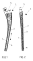
- a hollow rasp 1 is shown, which is designed for the removal of the human femur in the area of the hip joint. Therefore, the shape (Fig. 1) is also reminiscent of the shape of a hip stem of an artificial hip joint.
- the hollow rasp has a connector 5 for a handle.
- This is designed in a suitable form and embedded with one part in the proximal part of the rasp and fastened there.
- the hollow rasp 1 consists of a hollow tube 2. Its wall 3 is provided with a scraping profile 4, which can be produced, for example, by punching a sheet before rolling it up around a mandrel.
- the scraping profile 3 is designed such that it acts only in one direction of movement of the rasp, preferably when the rasp 1 is moved in the direction of the arrow B in FIG. 1. The scraping material is forced into the interior of the hollow tube 2.
- a suction unit (not shown) can be connected to the proximal section of the rasp 1, through which the removal material can be sucked off. This is to symbolize the arrow A in Fig. 1.
- a longitudinal slot is provided from distal to proximal in the wall 3 of the hollow tube 2.
- the slot gives the rasp a certain compensating spring effect in the peripheral area.
Abstract
Description
Die Erfindung betrifft eine Hohlschaftraspel.The invention relates to a hollow rasp.
Vor der Implantation einer stielförmigen Endoprothese in einen Röhrenknochen, beispielsweise in den menschlichen Femur, wird dieser an seinem gelenkseitigen Ende reseziert und eine Ausfräsung der Spongiosa und Entfernung von Knochenmark vorgenommen. In den ausgefrästen Raum kann sodann der Stiel der Endoprothese eingebracht werden, wo er zementlos oder unter Anwendung von Zement (Methylmetacrylat) fixiert wird. Ein typisches Beispiel für eine derartige stielförmige Endoprothese ist der Hüftstiel eines künstlichen Hüftgelenks.Before a stem-shaped endoprosthesis is implanted in a long bone, for example in the human femur, the end of the joint is resected and the cancellous bone is milled out and bone marrow is removed. The stem of the endoprosthesis can then be inserted into the milled space, where it is fixed without cement or using cement (methyl methacrylate). A typical example of such a stem-shaped endoprosthesis is the hip stem of an artificial hip joint.
Häufig verwendete und aus der Praxis bekannte Werkzeuge zum Ausräumen des Spongiosaraumes bestehen aus einer massiven Raspel, welche die Form des Stielteils der Endoprothese aufweist und an deren proximalen Ende ein Handgriff für die Handhabung durch den Operateur angebracht ist.Often used and known from practice tools for clearing out the cancellous space consist of a solid rasp, which has the shape of the stem part of the endoprosthesis and at the proximal end of which a handle is attached for handling by the surgeon.
Bereits dieser Operationsschritt des Ausräumens des Spongiosa und Markraumes ist mit erheblichen Risiken verbunden. So ist beobachtet worden (Wenda et. al. in "Unfallchirurg", 1990, Seiten 56 bis 61), daß bereits beim Aufraspeln des Spongiosaraumes vermehrt Embolien und/oder Thrombosen auftreten, die in der Praxis während der Operation zu zusätzlichen schwersten Komplikationen aber auch zum Tode des Patienten führen können. Ein Grund hierfür ist die vermehrte Knochenmarksfettausschüttung, welche zu Fettembolien beim Patienten führen können.Even this operation step of clearing out the cancellous bone and medullary space is associated with considerable risks. It has been observed (Wenda et. Al. In "Unfallchirurg", 1990, pages 56 to 61) that increased embolism and / or thrombosis already occur when the spongiosa area is rasped, which in practice also leads to the most serious complications during the operation can lead to the death of the patient. One reason for this is the increased release of bone marrow fat, which can lead to fat embolism in the patient.
Eine Knochenraspel mit einem im Inneren vorgesehenen Kanal ist bekannt aus der DE-39 07 256 A1, mit der versucht wird, beim Ausfräsen eines Röhrenknochens abgetrennte Knochenspäne und Knochenmarksstückchen in das Innere der Raspel zu leiten und von dort gegebenenfalls mit einer speziellen Vorrichtung abzusaugen. Diese Hohlschaftraspel besteht in einer konkreten Ausführungsform aus dem Raspelkörper, in welchem der Sammelkanal für die Knochenspäne und Knochenmarksstückchen ausgebildet ist als eine Sackbohrung. Die Späne etc. sollen durch in der Wandung vorgesehene Durchtrittsöffnungen von außen nach innen in die Raspel eintreten.A bone rasp with a channel provided on the inside is known from DE-39 07 256 A1, with which an attempt is made to guide separated bone chips and bone marrow fragments into the interior of the rasp when milling out a tubular bone and, if appropriate, to suction them off from there with a special device. In a specific embodiment, this hollow shaft rasp consists of the rasp body in which the collecting duct for the bone chips and Bone marrow pieces are designed as blind holes. The chips etc. are to enter the rasp from the outside in through the passage openings provided in the wall.
Die Knochenraspel gemäß der genannten Druckschrift schneidet oder spant sowohl beim Hineinstoßen der Raspel in den Knochenmarksraum, als auch beim Herausziehen. Nun ist die Konsistenz der im Markraum befindlichen Masse so, daß die erwähnten Durchtrittsöffnungen sehr schnell verstopfen, so daß die Raspel dann lediglich die Wirkung einer weiter oben erwähnten massiven Raspel hat.The rasp bone cuts or cuts both when the rasp is pushed into the bone marrow space and when it is pulled out. Now the consistency of the mass in the medullary cavity is such that the passage openings mentioned clog very quickly, so that the rasp then only has the effect of a massive rasp mentioned above.
Vor diesem Hintergrund ist es nun die Aufgabe der vorliegenden Erfindung, ein Werkzeug anzugeben, mit dem der Spongiosa- und Markraum eines Röhrenknochens zur Präparation einer Implantation ausgeräumt werden kann, bei dessen Anwendung das Risiko von Thrombosen und/oder Embolien erheblich reduziert ist, wobei die aufgeführten Nachteile der vorerwähnten Knochenraspel mit Innenkanal vermieden werden sollen.Against this background, it is the object of the present invention to provide a tool with which the cancellous bone and marrow space of a long bone can be cleared for the preparation of an implantation, the use of which significantly reduces the risk of thrombosis and / or embolism, the Disadvantages of the above-mentioned bone rasp with inner channel should be avoided.
Erfindungsgemäß besteht das Werkzeug aus einer Hohlschaftraspel, an welche proximal ein Handgriff für die Handhabung durch den Operateur anbringbar ist. Die Hohlschaftraspel besteht aus einem Hohlrohr, in dessen Wandung ein Schabeprofil eingearbeitet ist. Dieses Schabeprofil wirkt nur unidirektional, vorzugsweise beim Eindringen in den Röhrenknochen. Wird die Raspel aus dem Röhrenknochen herausgezogen, wirkt das Schabeprofil nicht. Im Gegensatz hierzu wirkt die Raspel gemäß der DE-39 07 256 A1 in beiden Richtungen, was neben der relativ hohen Wandungsdicke zu einem schnellen Verstopfen der Durchtrittsöffnungen führt.According to the invention, the tool consists of a hollow rasp to which a handle can be attached proximally for handling by the surgeon. The hollow rasp consists of a hollow tube, in the wall of which a scraping profile is incorporated. This scraping profile is only unidirectional, preferably when penetrating the long bones. If the rasp is pulled out of the long bone, the scraping profile does not work. In contrast to this, the rasp according to DE-39 07 256 A1 acts in both directions, which, in addition to the relatively high wall thickness, leads to rapid clogging of the passage openings.
Die Wirkung der erfindungsgemäßen Hohlschaftraspel ist die folgende: beim Vorantreiben der Raspel in den Röhrenknochen wird Spongiosa und Knochenmark in das Innere des Hohlrohres gedrängt. Im Gegensatz dazu wurde bei herkömmlichen Werkzeugen das Knochenmark und die Spongiosa gegen die Knocheninrienwand gedrückt mit der Folge, daß zumindest Knochenmarkfett in die Blutbahn des Patienten übertreten konnte und so zu Fettembolien führte. Vorliegend nun sammelt sich sämtlicher Abraum im Inneren der Hohlschaftraspel.The effect of the hollow rasp according to the invention is as follows: when the rasp is pushed forward in the long bones, cancellous bone and bone marrow are forced into the interior of the hollow tube. In contrast, in conventional tools, the bone marrow and cancellous bone were pressed against the wall of the internal bone, with the result that at least bone marrow fat in could cross the patient's bloodstream, leading to fat embolism. In the present case, all overburden collects inside the hollow rasp.
Vorzugsweise ist die Hohlschaftraspel medial mit einem Längsschlitz versehen. Dieser Längsschlitz ist vorteilhaft auf der ganzen Länge von distal nach proximal vorgesehen. Er verleiht der Hohlschaftraspel eine federnde Wirkung in ihrem Umfangsbereich. Hierdurch kann die Wandung der Raspel eine Ausgleichsbewegung in Abhängigkeit der jeweilig herrschenden Druckverhältnisse ausführen.The hollow rasp is preferably provided with a longitudinal slit medially. This longitudinal slit is advantageously provided over the entire length from distal to proximal. It gives the hollow rasp a resilient effect in its peripheral area. As a result, the wall of the rasp can perform a compensatory movement depending on the prevailing pressure conditions.
Gemäß einer besonders vorteilhaften Ausführungsform weist die erfindungsgemäße Raspel proximal ein Anschlußstück auf, an das eine Absaugeinheit anschließbar ist. Dies ist für sich genommen bereits aus der obengenannten Druckschrift DE-39 07 256 A1 bekannt. Hierdurch wird das Risiko einer Thrombose oder Embolie noch weiter reduziert, da es nämlich möglich ist, durch das Aufraspeln bereits in das Innere des Hohlrohres gelangtes Spongiosa- und Knochenmarksmaterial nach außen abzusaugen, so daß es in keinem Falle zu einem Stau vom Material im Hohlrohrinneren kommen kann.According to a particularly advantageous embodiment, the rasp according to the invention has a connection piece proximally to which a suction unit can be connected. This is already known from DE-39 07 256 A1. This further reduces the risk of thrombosis or embolism, since it is possible to suck out spongiosa and bone marrow material that has already reached the inside of the hollow tube by rasping, so that there is in no case a jam from the material inside the hollow tube can.
Vorteilhaft weist die erfindungsgemäße Hohlschaftraspel im wesentlichen die Außenkontur des Stieles der zu implantierenden Endoprothese auf, wie schon aus der Zeichnungsfigur der genannten Druckschrift bekannt. Gemäß dieser Ausführungsform wird die Hohlschaftraspel also nicht die Form eines hohlzylindrischen Rohres aufweisen. Der Vorteil dieser Formgebung besteht darin, daß der auszufräsende Raum von vorn herein die Form annehmen wird, damit der Stiel der Endoprothese genau dort hineinpaßt.Advantageously, the hollow shaft rasp according to the invention essentially has the outer contour of the stem of the endoprosthesis to be implanted, as is already known from the drawing figure of the cited document. According to this embodiment, the hollow rasp will not have the shape of a hollow cylindrical tube. The advantage of this design is that the space to be milled will take shape from the start so that the stem of the endoprosthesis fits exactly there.
An dieser Stelle sei noch auf die DE-92 17 486 U1 hingewiesen, die ebenfalls eine Raspel zur Vorbereitung einer Knochenöffnung betrifft. Aus dieser ist allerdings keine Hohlschaftraspel bekannt, sondern das Prinzip des lösbaren Griffes am proximalen Ende der Raspel, wie dies im Oberbegriff des Anspruchs 1 vorausgesetzt wird.At this point, reference is also made to DE-92 17 486 U1, which also relates to a rasp for preparing a bone opening. From this, however, no hollow rasp is known, but the principle of the releasable handle at the proximal end of the rasp, as is assumed in the preamble of
Die Erfindung wird anhand eines Ausführungsbeispieles gemäß der Zeichnungsfiguren näher erläutert. Hierbei zeigt:
- Fig. 1
- eine Seitenansicht eines Ausführungsbeispieles der Hohlschaftraspel, teilweise geschnitten, und
- Fig. 2
- die Ansicht auf die Raspel gemäß Fig. 1 von medial gesehen.
- Fig. 1
- a side view of an embodiment of the hollow rasp, partially cut, and
- Fig. 2
- the view of the rasp of FIG. 1 seen from the medial.
In den Zeichnungsfiguren ist eine Hohlschaftraspel 1 dargestellt, die für das Ausräumen des menschlichen Femurknochens im Bereich des Hüftgelenks ausgebildet ist. Daher erinnert die Form (Fig. 1) auch an die Form eines Hüftstiels eines künstlichen Hüftgelenks.In the drawing figures, a
Proximal weist die Hohlschaftraspel ein Anschlußstück 5 für einen Handgriff auf. Dieses ist in geeigneter Form ausgebildet und mit einem Teil in den proximalen Teil der Raspel eingelassen und dort befestigt. Die Hohlschaftraspel 1 besteht aus einem Hohlrohr 2. Dessen Wandung 3 ist mit einem Schabeprofil 4 versehen, das beispielsweise durch Stanzen eines Bleches vor dem Aufrollen um einen Dorn hergestellt sein kann. Das Schabeprofil 3 ist so ausgebildet, daß es nur in einer Bewegungsrichtung der Raspel wirkt, vorzugsweise bei Bewegung der Raspel 1 in Richtung des Pfeiles B in Fig. 1. Dabei wird das Abraummaterial in das Innere des Hohlrohres 2 gedrängt.Proximally, the hollow rasp has a
Gemäß einer besonders bevorzugten Ausführung kann vorgesehen sein, am proximalen Abschnitt der Raspel 1 eine Absaugeinheit (nicht dargestellt) anzuschließen, durch welche das Abraummaterial abgesogen werden kann. Dies soll der Pfeil A in Fig. 1 versinnbildlichen.According to a particularly preferred embodiment, a suction unit (not shown) can be connected to the proximal section of the
Aus Fig. 2 ist ersichtlich, daß von medial gesehen ein Längsschlitz von distal nach proximal in der Wandung 3 des Hohlrohres 2 vorgesehen ist. Der Schlitz verleiht der Raspel eine gewisse ausgleichende Federwirkung im Umfangsbereich.From Fig. 2 it can be seen that, seen medially, a longitudinal slot is provided from distal to proximal in the
Claims (3)
Applications Claiming Priority (2)
| Application Number | Priority Date | Filing Date | Title |
|---|---|---|---|
| DE4323873A DE4323873C2 (en) | 1993-07-16 | 1993-07-16 | Hollow rasp |
| DE4323873 | 1993-07-16 |
Publications (2)
| Publication Number | Publication Date |
|---|---|
| EP0634145A1 true EP0634145A1 (en) | 1995-01-18 |
| EP0634145B1 EP0634145B1 (en) | 1997-05-14 |
Family
ID=6492972
Family Applications (1)
| Application Number | Title | Priority Date | Filing Date |
|---|---|---|---|
| EP94110566A Expired - Lifetime EP0634145B1 (en) | 1993-07-16 | 1994-07-07 | Rasp with hollow shaft |
Country Status (3)
| Country | Link |
|---|---|
| EP (1) | EP0634145B1 (en) |
| DE (2) | DE4323873C2 (en) |
| ES (1) | ES2101394T3 (en) |
Cited By (7)
| Publication number | Priority date | Publication date | Assignee | Title |
|---|---|---|---|---|
| EP0745352A2 (en) * | 1995-05-31 | 1996-12-04 | Zsolt Szabo | Intramedullary rasp |
| EP0747015A1 (en) | 1995-06-09 | 1996-12-11 | MERCK PATENT GmbH | Instrumentation for a medullary canal preparation |
| EP0908158A2 (en) * | 1997-09-16 | 1999-04-14 | Franz Copf | Set of prostheses of different sizes |
| WO2000045715A1 (en) * | 1999-02-01 | 2000-08-10 | Eska Implants Gmbh & Co. | Hollow rasp for preparing a tubular bone |
| WO2004089226A1 (en) * | 2003-04-11 | 2004-10-21 | Martin Nolde | Rasp attachment for a motor-driven surgical hand-held device |
| FR2859619A1 (en) | 2003-09-16 | 2005-03-18 | Jean Christophe Grimard | Intra-medullary canal grater for use in articular arthroplasty, has body disposed along axis parallel to axis of intra-medullary canal, and knuckle thread formed on body for accommodating band provided with cutting edges |
| DE202011051261U1 (en) | 2011-09-12 | 2011-11-02 | Bertrand Prevot | Surgical hand tool |
Families Citing this family (3)
| Publication number | Priority date | Publication date | Assignee | Title |
|---|---|---|---|---|
| DE19604494A1 (en) * | 1996-02-08 | 1997-08-14 | Zimmer Ltd | Tool for implanting an endoprosthesis |
| DE19737792C2 (en) * | 1997-08-29 | 1999-07-08 | Aesculap Ag & Co Kg | Bone rasp |
| DE19820506C1 (en) * | 1998-05-08 | 2000-01-05 | Eska Implants Gmbh & Co | Device for preparing a human long bone for the implantation of a bone implant and method for operating this device |
Citations (6)
| Publication number | Priority date | Publication date | Assignee | Title |
|---|---|---|---|---|
| DE3433105A1 (en) * | 1984-09-08 | 1986-03-20 | Kernforschungszentrum Karlsruhe Gmbh, 7500 Karlsruhe | Device for the fixation of the fracture ends of a bone |
| US4819635A (en) * | 1987-09-18 | 1989-04-11 | Henry Shapiro | Tubular microsurgery cutting apparatus |
| EP0331626A2 (en) * | 1988-03-01 | 1989-09-06 | GebràDer Sulzer Aktiengesellschaft | Rasp-like reamer instrument |
| US5006121A (en) * | 1990-04-23 | 1991-04-09 | Artifex Ltd. | Bone broaches and methods of manufacturing thereof |
| DE9212906U1 (en) * | 1992-09-25 | 1992-11-26 | S + G Implants Gmbh, 2400 Luebeck, De | |
| US5203653A (en) * | 1991-12-30 | 1993-04-20 | Pfizer Hospital Products Group, Inc. | Reamer for shaping bone sockets |
Family Cites Families (2)
| Publication number | Priority date | Publication date | Assignee | Title |
|---|---|---|---|---|
| DE3907256A1 (en) * | 1989-03-07 | 1990-09-20 | Orthoplant Endoprothetik | Bone rasp |
| DE9217486U1 (en) * | 1992-12-22 | 1993-02-18 | Aesculap Ag, 7200 Tuttlingen, De |
-
1993
- 1993-07-16 DE DE4323873A patent/DE4323873C2/en not_active Expired - Fee Related
-
1994
- 1994-07-07 DE DE59402717T patent/DE59402717D1/en not_active Expired - Fee Related
- 1994-07-07 EP EP94110566A patent/EP0634145B1/en not_active Expired - Lifetime
- 1994-07-07 ES ES94110566T patent/ES2101394T3/en not_active Expired - Lifetime
Patent Citations (6)
| Publication number | Priority date | Publication date | Assignee | Title |
|---|---|---|---|---|
| DE3433105A1 (en) * | 1984-09-08 | 1986-03-20 | Kernforschungszentrum Karlsruhe Gmbh, 7500 Karlsruhe | Device for the fixation of the fracture ends of a bone |
| US4819635A (en) * | 1987-09-18 | 1989-04-11 | Henry Shapiro | Tubular microsurgery cutting apparatus |
| EP0331626A2 (en) * | 1988-03-01 | 1989-09-06 | GebràDer Sulzer Aktiengesellschaft | Rasp-like reamer instrument |
| US5006121A (en) * | 1990-04-23 | 1991-04-09 | Artifex Ltd. | Bone broaches and methods of manufacturing thereof |
| US5203653A (en) * | 1991-12-30 | 1993-04-20 | Pfizer Hospital Products Group, Inc. | Reamer for shaping bone sockets |
| DE9212906U1 (en) * | 1992-09-25 | 1992-11-26 | S + G Implants Gmbh, 2400 Luebeck, De |
Cited By (13)
| Publication number | Priority date | Publication date | Assignee | Title |
|---|---|---|---|---|
| EP0745352A2 (en) * | 1995-05-31 | 1996-12-04 | Zsolt Szabo | Intramedullary rasp |
| EP0745352A3 (en) * | 1995-05-31 | 1996-12-11 | Zsolt Szabo | Intramedullary rasp |
| US5681315A (en) * | 1995-05-31 | 1997-10-28 | Szabo; Zsolt | Bone marrow rasp |
| EP0747015A1 (en) | 1995-06-09 | 1996-12-11 | MERCK PATENT GmbH | Instrumentation for a medullary canal preparation |
| EP0908158A2 (en) * | 1997-09-16 | 1999-04-14 | Franz Copf | Set of prostheses of different sizes |
| EP0908158A3 (en) * | 1997-09-16 | 1999-12-08 | Franz Copf | Set of prostheses of different sizes |
| WO2000045715A1 (en) * | 1999-02-01 | 2000-08-10 | Eska Implants Gmbh & Co. | Hollow rasp for preparing a tubular bone |
| US6660041B1 (en) | 1999-02-01 | 2003-12-09 | Eska Implants Gmbh & Co. | Hollow rasp for preparing a tubular bone |
| WO2004089226A1 (en) * | 2003-04-11 | 2004-10-21 | Martin Nolde | Rasp attachment for a motor-driven surgical hand-held device |
| US8021364B2 (en) | 2003-04-11 | 2011-09-20 | Martin Nolde | Rasp attachment for a motor-driven surgical hand-held device |
| FR2859619A1 (en) | 2003-09-16 | 2005-03-18 | Jean Christophe Grimard | Intra-medullary canal grater for use in articular arthroplasty, has body disposed along axis parallel to axis of intra-medullary canal, and knuckle thread formed on body for accommodating band provided with cutting edges |
| EP1516590A1 (en) | 2003-09-16 | 2005-03-23 | Jean-Christophe Grimard | Device for rasping the bone canal and its manufacturing assembly |
| DE202011051261U1 (en) | 2011-09-12 | 2011-11-02 | Bertrand Prevot | Surgical hand tool |
Also Published As
| Publication number | Publication date |
|---|---|
| DE4323873A1 (en) | 1995-01-19 |
| DE4323873C2 (en) | 1996-07-18 |
| EP0634145B1 (en) | 1997-05-14 |
| ES2101394T3 (en) | 1997-07-01 |
| DE59402717D1 (en) | 1997-06-19 |
Similar Documents
| Publication | Publication Date | Title |
|---|---|---|
| EP0888759B1 (en) | Instrument for introduction of an insert of an implant into the associated shell | |
| DE69720803T2 (en) | RASP FOR PROCESSING A MARKING CHANNEL OF A BONE | |
| DE4143453C2 (en) | Centering element for bone implants | |
| DE60113873T2 (en) | DRILLING DEVICE WITH SKULL DRILL FOR BONE RECYCLING | |
| DE69729140T2 (en) | Instrumentation for the implantation of a surgical implant | |
| DE69433702T2 (en) | Two feedthrough protection device for surgery of the intervertebral space | |
| DE69637186T2 (en) | Device, with a protective device that has a passage with a non-circular cross-section for a protected access to the spine | |
| DE3534747C2 (en) | ||
| EP1284690B1 (en) | Instruments used for inserting a hip cup | |
| EP0745352B1 (en) | Intramedullary rasp | |
| DE202011111061U1 (en) | Orthopedic milling device for bone preparation, in particular joint preparation | |
| DE4039064C2 (en) | ||
| EP0727197A1 (en) | Apparatus for placing an intramedullary plug in the medullary canal of a tubular bone and intramedullary plug for a tubular bone | |
| EP1294322A1 (en) | Device for injecting bone cement | |
| EP0619097A1 (en) | Rasp and detachable handle for preparing the medullary canal of a bone which is to receive a prosthesis | |
| EP0985387A1 (en) | Kit for implanting a cementable endoprosthesis | |
| EP0434604A1 (en) | Anchored shaft for a femoral prosthesis | |
| DE202005016761U1 (en) | Surgical milling cutter in particular for removal of tissue from facet joint at spine, comprises handle to be attached with quick joining mechanism | |
| EP0634145B1 (en) | Rasp with hollow shaft | |
| DE69738227T2 (en) | Drilling apparatus for embedding an implant in bone tissue | |
| DE60104184T2 (en) | BONE GRAFT COMPRESSOR | |
| DE3907256A1 (en) | Bone rasp | |
| WO2004064688A1 (en) | Hip prosthesis comprising a shaft to be fixed in the medullary canal of the femur | |
| EP1106143B1 (en) | Prosthetic system | |
| DE4313201C2 (en) | Prosthetic socket set |
Legal Events
| Date | Code | Title | Description |
|---|---|---|---|
| PUAI | Public reference made under article 153(3) epc to a published international application that has entered the european phase |
Free format text: ORIGINAL CODE: 0009012 |
|
| AK | Designated contracting states |
Kind code of ref document: A1 Designated state(s): CH DE ES FR GB IT LI |
|
| 17P | Request for examination filed |
Effective date: 19950110 |
|
| RAP1 | Party data changed (applicant data changed or rights of an application transferred) |
Owner name: ESKA IMPLANTS GMBH & CO. |
|
| RAP3 | Party data changed (applicant data changed or rights of an application transferred) |
Owner name: ESKA IMPLANTS GMBH & CO. |
|
| GRAG | Despatch of communication of intention to grant |
Free format text: ORIGINAL CODE: EPIDOS AGRA |
|
| 17Q | First examination report despatched |
Effective date: 19960802 |
|
| GRAH | Despatch of communication of intention to grant a patent |
Free format text: ORIGINAL CODE: EPIDOS IGRA |
|
| GRAH | Despatch of communication of intention to grant a patent |
Free format text: ORIGINAL CODE: EPIDOS IGRA |
|
| GRAA | (expected) grant |
Free format text: ORIGINAL CODE: 0009210 |
|
| AK | Designated contracting states |
Kind code of ref document: B1 Designated state(s): CH DE ES FR GB IT LI |
|
| REG | Reference to a national code |
Ref country code: CH Ref legal event code: NV Representative=s name: DIPL.-ING. ETH H. R. WERFFELI PATENTANWALT Ref country code: CH Ref legal event code: EP |
|
| ITF | It: translation for a ep patent filed |
Owner name: BUGNION S.P.A. |
|
| GBT | Gb: translation of ep patent filed (gb section 77(6)(a)/1977) |
Effective date: 19970515 |
|
| REF | Corresponds to: |
Ref document number: 59402717 Country of ref document: DE Date of ref document: 19970619 |
|
| REG | Reference to a national code |
Ref country code: ES Ref legal event code: FG2A Ref document number: 2101394 Country of ref document: ES Kind code of ref document: T3 |
|
| ET | Fr: translation filed | ||
| PLBE | No opposition filed within time limit |
Free format text: ORIGINAL CODE: 0009261 |
|
| STAA | Information on the status of an ep patent application or granted ep patent |
Free format text: STATUS: NO OPPOSITION FILED WITHIN TIME LIMIT |
|
| 26N | No opposition filed | ||
| REG | Reference to a national code |
Ref country code: GB Ref legal event code: IF02 |
|
| PGFP | Annual fee paid to national office [announced via postgrant information from national office to epo] |
Ref country code: GB Payment date: 20050627 Year of fee payment: 12 |
|
| PGFP | Annual fee paid to national office [announced via postgrant information from national office to epo] |
Ref country code: FR Payment date: 20050719 Year of fee payment: 12 |
|
| PGFP | Annual fee paid to national office [announced via postgrant information from national office to epo] |
Ref country code: ES Payment date: 20050721 Year of fee payment: 12 |
|
| PGFP | Annual fee paid to national office [announced via postgrant information from national office to epo] |
Ref country code: CH Payment date: 20050722 Year of fee payment: 12 |
|
| PG25 | Lapsed in a contracting state [announced via postgrant information from national office to epo] |
Ref country code: GB Free format text: LAPSE BECAUSE OF NON-PAYMENT OF DUE FEES Effective date: 20060707 |
|
| PG25 | Lapsed in a contracting state [announced via postgrant information from national office to epo] |
Ref country code: LI Free format text: LAPSE BECAUSE OF NON-PAYMENT OF DUE FEES Effective date: 20060731 Ref country code: CH Free format text: LAPSE BECAUSE OF NON-PAYMENT OF DUE FEES Effective date: 20060731 |
|
| PGFP | Annual fee paid to national office [announced via postgrant information from national office to epo] |
Ref country code: IT Payment date: 20060731 Year of fee payment: 13 |
|
| REG | Reference to a national code |
Ref country code: CH Ref legal event code: PL |
|
| GBPC | Gb: european patent ceased through non-payment of renewal fee |
Effective date: 20060707 |
|
| REG | Reference to a national code |
Ref country code: FR Ref legal event code: ST Effective date: 20070330 |
|
| REG | Reference to a national code |
Ref country code: ES Ref legal event code: FD2A Effective date: 20060708 |
|
| PG25 | Lapsed in a contracting state [announced via postgrant information from national office to epo] |
Ref country code: ES Free format text: LAPSE BECAUSE OF NON-PAYMENT OF DUE FEES Effective date: 20060708 |
|
| PG25 | Lapsed in a contracting state [announced via postgrant information from national office to epo] |
Ref country code: FR Free format text: LAPSE BECAUSE OF NON-PAYMENT OF DUE FEES Effective date: 20060731 |
|
| PG25 | Lapsed in a contracting state [announced via postgrant information from national office to epo] |
Ref country code: IT Free format text: LAPSE BECAUSE OF NON-PAYMENT OF DUE FEES Effective date: 20070707 |
|
| PGFP | Annual fee paid to national office [announced via postgrant information from national office to epo] |
Ref country code: DE Payment date: 20090730 Year of fee payment: 16 |
|
| PG25 | Lapsed in a contracting state [announced via postgrant information from national office to epo] |
Ref country code: DE Free format text: LAPSE BECAUSE OF NON-PAYMENT OF DUE FEES Effective date: 20110201 |
|
| REG | Reference to a national code |
Ref country code: DE Ref legal event code: R119 Ref document number: 59402717 Country of ref document: DE Effective date: 20110201 |
|
| REG | Reference to a national code |
Ref country code: DE Ref legal event code: R081 Ref document number: 59402717 Country of ref document: DE Owner name: ORTHODYNAMICS GMBH, DE Free format text: FORMER OWNER: ESKA IMPLANTS GMBH & CO.KG, 23556 LUEBECK, DE Effective date: 20110707 |