EP0610007A2 - High efficiency encoding and decoding - Google Patents
High efficiency encoding and decoding Download PDFInfo
- Publication number
- EP0610007A2 EP0610007A2 EP19940300502 EP94300502A EP0610007A2 EP 0610007 A2 EP0610007 A2 EP 0610007A2 EP 19940300502 EP19940300502 EP 19940300502 EP 94300502 A EP94300502 A EP 94300502A EP 0610007 A2 EP0610007 A2 EP 0610007A2
- Authority
- EP
- European Patent Office
- Prior art keywords
- bit allocation
- channels
- information signals
- signals
- block
- Prior art date
- Legal status (The legal status is an assumption and is not a legal conclusion. Google has not performed a legal analysis and makes no representation as to the accuracy of the status listed.)
- Granted
Links
Images


Classifications
-
- H—ELECTRICITY
- H04—ELECTRIC COMMUNICATION TECHNIQUE
- H04B—TRANSMISSION
- H04B1/00—Details of transmission systems, not covered by a single one of groups H04B3/00 - H04B13/00; Details of transmission systems not characterised by the medium used for transmission
- H04B1/66—Details of transmission systems, not covered by a single one of groups H04B3/00 - H04B13/00; Details of transmission systems not characterised by the medium used for transmission for reducing bandwidth of signals; for improving efficiency of transmission
- H04B1/665—Details of transmission systems, not covered by a single one of groups H04B3/00 - H04B13/00; Details of transmission systems not characterised by the medium used for transmission for reducing bandwidth of signals; for improving efficiency of transmission using psychoacoustic properties of the ear, e.g. masking effect
Definitions
- This invention relates to high efficiency encoding methods and devices for encoding input digital data by high efficiency encoding, whereupon the encoded data may be transmitted or recorded, and to high efficiency decoding methods and devices for reproducing and decoding the encoded data to produce replay data.
- a sub-band coding (SBC) system which is a non-block forming frequency band dividing system which comprises dividing the time-domain signals into signals of plural frequency bands without dividing the time-domain audio signals into plural blocks
- SBC sub-band coding
- a block-forming frequency band dividing system which comprises dividing time-domain signals into plural blocks, transforming the resulting blocks into frequency-domain signals by orthogonal transformation, and encoding the resulting frequency-domain signals from one frequency band to another, also known as transform coding.
- high efficiency encoding comprising a combination of sub-band coding and transform coding, in which the time-domain signals are divided into signals of plural frequency bands by sub-band coding, and the signals of the respective bands are orthogonally transformed into frequency-domain signals which are then encoded from one band to another.
- a filter employed in the above methods may be exemplified by a quadrature mirror filter (QMF) discussed in 1976 R.E. Crochiere, Digital Coding of Speech in Sub-bands, Bell Syst. Tech. J., Vol. 55, No.8, 1976.
- QMF quadrature mirror filter
- An equal-band filter dividing method employing a polyphase quadrature filter is discussed in ICASSP 83, Boston, Polyphase Quadrature Filter - A New Sub-band Coding Technique, by Joseph H. Rothweiler.
- the orthogonal transform may be enumerated by an orthogonal transform consisting in forming input audio signals into blocks at an interval of a pre-set unit time period (frame), and processing the resulting blocks by a fast Fourier transform (FFT), discrete cosine transform (DCT) or modified DCT (MDCT) for transforming time-domain signals into frequency-domain signals.
- FFT fast Fourier transform
- DCT discrete cosine transform
- MDCT modified DCT
- the frequency bands are selected to take into account the characteristics of the human aural sense. That is, the audio signals are divided into a plurality of bands, for example 25 bands, known as critical bands, in which the bandwidths become broader in a direction of increasing frequencies.
- a pre-set number of bits are allocated to each band, or variable numbers of bits are allocated to each band by way of adaptive bit allocation. For example, when encoding coefficient data obtained by MDCT by bit allocation, the MDCT coefficient data of the respective bands obtained by block-based MDCT are encoded by adaptive numbers of bits. The following two bit allocation methods are known.
- bit allocation is made based on the magnitudes of the signals of the respective bands.
- the quantization noise spectrum becomes flatter and the noise energy becomes minimum.
- the noise as actually perceived by the ear is not optimum because the aural masking effect is not utilized.
- pre-echo means a phenomenon in which the quantization noise produced directly before the small information signal is abruptly changed to the larger information signal is heard without being covered by backward masking to cause deterioration in the sound quality.
- a high efficiency encoding method in which pre-set bit allocation is made for digital information signals of plural channels and the encoded information signals are obtained on the basis of the allocated bits, characterised in that the amount of bit allocation among the channels is performed based on temporal changes of the information signals of the respective channels.
- a preferred embodiment of the invention described in detail hereinbelow seeks to provide a method for bit allocation which is free from pre-echo insofar as the human aural sense is concerned.
- pre-echo is prevented by preferentially allocating at least a part of the bits that may be used for bit allocation to channels having larger temporal changes of the information signals in dependence upon the temporal changes of the information signals between channels.
- Detection and decision of the magnitude of temporal changes of the information signals in dependence upon temporal changes of a scale factor as normalization information of the frequency components of the information signals is effective for avoiding new arithmetic and logical operations because this parameter forms a part of the sub-data to be transmitted from the encoder to the decoder.
- detection and decision based on temporal changes of the amplitude information of sub-blocks on a time scale obtained on further division of the time width of the block having the scale factor is also desirable for performance.
- Changing the bit allocation not only between channels but also in the channels based on the temporal changes of the signal information between neighboring blocks in the channels is effective in further reducing pre-echo.
- a structure in which an output of non-block forming frequency analysis means such as a filter, an output of block forming frequency analysis, such as an orthogonal transform, or an output of the non-block forming frequency analysis mapped on the frequency scale by block-forming frequency analysis, such as an orthogonal transform, may be employed.
- bit allocation it is possible to allocate a portion of the bits available for bit allocation as a first bit allocation depending on the information signal spectrum of the respective channels and to employ the remaining bits by appendage to the first bit allocation.
- bit allocation can be made for the channels in conformity with the temporal characteristics of the information signals and among the channels.
- the block size of the orthogonal transform is adaptively changed depending on time characteristics of the information signals, at the same time that the bit allocation is made between the channels, it becomes possible to increase the block length to raise the frequency resolution if the information signal are sub-steady signals, while it is also possible to raise the time resolution to reduce the time of occurrence of pre-echo to prevent the sound quality from being lowered if the information signals are non-steady signals.
- the preferred embodiment provides a system which is capable of reducing deterioration in sound quality due to pre-echo likely to be produced in high efficiency encoding and which is convenient for an audio recording and replay of cinema or an audio system in which high sound quality is necessary.
- input digital signals are divided by a filter or the like into a plurality of frequency bands and orthogonally transformed from one frequency band to another to produce frequency-domain spectral data which is encoded by adaptive bit allocation on the basis of the critical bands which take into account the characteristics of the human aural sense as later explained.
- the critical bands are sub-divided into blocks as the frequency is increased.
- the frequency bands may naturally be of equal widths in the case of the non-block forming system which is performed with the aid of a filter or the like.
- the block size or the block length is adaptively changed prior to orthogonal transform depending on the input signals and a floating operation is performed on the basis of critical bands or of blocks sub-divided from the critical bands for higher frequencies.
- the critical bands mean the frequency bands which result from frequency division taking into account the characteristics of the human aural sense. That is, the critical band is the band proper to a narrow band noise which masks a pure tone having the same intensity as the noise and the frequency in the vicinity of the noise frequency.
- the total frequency range of from 0 to 22 kHz is divided into e.g. 25 critical bands which are selected so that the bandwidths become broader towards the higher frequencies. 25 critical bands.
- audio PCM signals having the frequency range of from 0 to 22 kHz are supplied to an input terminal 10.
- the input signals are divided by a band-dividing filter 11, such as a QMF filter, into a band of from 0 to 11 kHz and a band of from 11 to 22 kHz.
- the frequency band of 0 to 11 kHz is divided by a band-dividing filter 12 into a band of 0 to 5.5 kHz and a band of 5.5 to 112 kHz.
- the 11 kHz to 22 kHz signal from the filter 11 is supplied to a modified discrete cosine transform (MDCT) circuit 13, as an example of an orthogonal transform circuit, while the 5.5 kHz to 11 kHz signal from the filter 12 is supplied to a modified discrete cosine transform (MDCT) circuit 14 and the 0 kHz to 5.5 kHz signal from the filter 12 is supplied to a modified discrete cosine transform (MDCT) circuit 15 so as to be processed with MDCT.
- MDCT modified discrete cosine transform
- Fig.2 shows a concrete example of a block size for the MDCT circuits 13 to 15.
- each of the three filter outputs has two block sizes for orthogonal transform. That is, for low frequency signals in the frequency band of 0 to 5.5 kHz and mid frequency signals in the frequency band of 5.5 to 11 kHz, each block is made up of 128 samples and 32 samples for the long block size (Fig.2A) and for the short block size (Fig.2B), respectively. On the other hand, for high frequency signals in the frequency band of 11 to 22 kHz, each block is made up of 256 samples and 32 samples for the long block size (Fig.2A) and for the short block size (Fig.2B), respectively. If the short block size is selected in this manner, the time resolution is increased towards the higher frequency and the number of kinds of the windows employed is decreased, with the number of samples of the orthogonal transform for each band remaining the same.
- the frequency-domain spectral data or MDCT coefficients, obtained by the MDCT circuits 13 to 15 by MDCT, are grouped according to the critical bands or, in a higher frequency range, according to small-sized blocks further divided from the critical bands, and transmitted to adaptive bit allocation encoding circuits 16, 17 and 18.
- the spectral data or the MDCT coefficient data are re-quantized depending on the number of bits allocated by the adaptive bit allocation encoding circuits 16, 17 and 18 for each of the critical bands or, in a higher frequency range, for each of the small-sized blocks further divided from the critical bands.
- the data thus encoded are outputted at output terminals 22, 24 and 26.
- the scale factor indicating which normalization is used as to the signal magnitude and the bit length information indicating which bit length has been used are transmitted simultaneously.
- the signal energies for the critical bands or those for the small-sized blocks sub-divided from the critical bands are found, such as by computing the roots of squared mean values of the respective amplitude values in the bands.
- the scale factor itself may naturally be employed for subsequent bit allocation. In such case, new energy computation becomes unnecessary resulting in saving in the hardware scale.
- the peak or mean values of the amplitude values may naturally be employed in place of the energies for the respective bands.
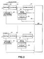
- Fig.3 The operation of the adaptive bit allocation circuit is explained by referring to Fig.3. Although there are eight channels in the present embodiment, only channels 1 and 8 are shown in Fig.3, while the remaining channels are omitted. The common portions to the channels are explained using the channel 1.
- Input information signals of the channel 1 are supplied to an input terminal 31.
- the input information signals are mapped from the time-domain signals on the frequency axis by a mapping function 32. If the filter is employed, the sub-band signals become time-domain samples. In the case of the orthogonal-transformed output, frequency-domain samples are produced. These samples are grouped into sets each consisting of plural samples by a block-forming function 33.
- temporal changes of MDCT input time-domain signals during mapping are calculated by a temporal change calculating function 44.
- the samples grouped into the blocks each consisting of plural samples by the block-forming function 33 are normalized by a normalizing function 37.
- the scale factor a coefficient for normalization, is calculated by a scale factor calculating function 35.
- the magnitude of tonality is calculated by a tonality calculating function 36.
- the parameter found in this manner is employed for bit allocation in a bit allocation function 38. If the number of bits which represents the MDCT coefficient and which is ready to be used for transmission or recording is assumed to be 800 kbps for the entire channels, the number of bits employed for the first bit allocation is determined in the present embodiment.
- the sum of absolute values of the differences between neighboring values of the signal spectral components divided by the number of signal spectral components is employed as an index. More precisely, the mean value of the differences between neighboring scale factor indices of the block-based scale factors for block floating is employed as the index.
- the scale factor index substantially corresponds to a logarithm of the scale factor.
- the amount of bits to be employed for the first bit allocation is associated with the value indicating the tonality and is set to a maximum value of 600 kbps and a minimum value of 300 kbps.
- Tm 1/WLmax ( ⁇ ABS (SFn - SFn - 1)
- Tav (1/CH)
- Tav channel-averaged tonality
- Tav found in this manner is associated with the first amount of bit allocation as shown in Fig.12.
- the proportion of distribution between allocation to the first bit allocation pattern and at least one other bit allocation to be appended thereto depends on the characteristics of temporal changes of the information signals.
- the time area in which the information signal amplitudes become abruptly larger is detected by comparing the peak values of the signal information for adjacent blocks for each time domain divided from the time block size for orthogonal transform to determine the proportion of distribution.
- Vt the sum for each channel of changes of the peak value of the time sub-block of each channel from a smaller value to a larger value, expressed in db
- Vm the magnitude of the largest one of the changes of the peak value of the time sub-block of each channel from a smaller value to a larger value, expressed in db
- Vmax m channel number Ch : number of channels
- Vab channel-averaged changes of the peak value of the time sub-block of each channel from a smaller value to a larger value, expressed in db
- Vav found in this manner is associated with the amount of the first bit allocation as shown in Fig.13.
- bit allocation is made for each channel for the first bit allocation.
- Adaptive bit allocation may naturally be made depending on the distribution of the scale factor on the frequency scale.
- effective bit allocation may be made by bit allocation between the channels depending on the distribution of the scale factor on the frequency scale for the totality of channels.
- the signal information of plural channels is mixed in the same sound field to reach left and right ears as in the case of speakers, it may be assumed that effective masking is made by the mixed signals of the totality of the channels. Therefore, it is effective to perform bit allocation so that the same noise level is achieved for the respective channels. To this end, it suffices to perform bit allocation in proportion to the magnitude of the scale factor indices.
- Bm the amount of first bit allocation for each channel
- B the amount of first bit allocation for totality of channels
- SFn scale factor index substantially corresponding to the logarithm of the peak value
- n band number of block floating
- bit allocation of bits not employed in the first bit allocation is carried out.
- bit allocations are carried out herein.
- Figs.8 and 9 illustrate the manner of bit allocation.
- more bits are allocated to the first bit allocation as shown in Fig.8.
- the amount of bits is decreased for the first bit allocation, as shown in Fig.9, whereas the amount of bits for the second bit allocation is increased, as shown in Fig.9, so that more bits are allocated to the signal spectrum having a larger level.
- second bit allocation is set so as to place emphasis on the low frequency side.
- there are a variety of patterns of bit allocation in which the amounts of bits of blocks of shorter time duration are distributed for the respective frequencies.
- plural patterns of bit allocation are provided in which the rates of bit allocation are different for the mid to low frequency range and the high frequency range. Such a pattern is selected in which the smaller the signal magnitude, the lesser is the amount of bit allocation to the higher frequency side. In this manner, it becomes possible to take advantage of the loudness effects in which the sensitivity for the higher frequency is lowered for a smaller signal magnitude.
- the present embodiment comprises, in addition to the above, a process of detecting the temporal change characteristics of the signals of the respective channels to change the amounts of bit allocation for the respective channels.
- An index representative of the temporal changes is found in the following manner.
- the bit allocating time blocks as time units of bit allocation of the information input signals of the respective channels, are temporally divided into four sub-blocks for each of which the peak value is found.
- the bits are distributed between the channels depending on the magnitude of the differences of the peak values of the sub-blocks which are changed from a smaller value to a larger value.
- T a + b + c + d + e + f + g + h.
- the bit allocation may be made by (C - t)*a/T, (C - t)*b/T, ....(C - t)*h/T bits.
- the t-bits are allocated preferentially. Consequently, more t-bits are allocated to this channel so that pre-echo may be decreased significantly.
- the t-bits may be allocated to one of them.
- the t-bits may be allocated to a woofer channel.
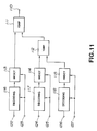
- Fig.11 shows a decoding circuit for decoding the high-efficiency coded signals.
- the quantized MDCT coefficients for the respective bands are supplied to input terminals 122, 124, 126 leading to inputs of decoding circuits 116, 117 and 118, while the block size information employed is supplied to input terminals 123, 125 and 127 which lead to the decoding circuits 116, 117 and 118 and also to inverse MDCT (IMDCT) circuits 113, 114 and 115.
- IMDCT inverse MDCT
- the decoding circuits 116, 117 and 118 release bit allocation using the adaptive bit allocation information.
- the frequency domain signals are transformed into time-domain signals.
- the time-domain signals of the partial range are decoded by inverse QMF (IQMF) circuits 111, 112 into the entire range of signals and supplied to an output terminal 110.
- IQMF inverse QMF
- the present embodiment provides a method of bit allocation which is aurally desirable for compression of temporally fluctuated information signals in a multi-channel system.
Abstract
Description
- This invention relates to high efficiency encoding methods and devices for encoding input digital data by high efficiency encoding, whereupon the encoded data may be transmitted or recorded, and to high efficiency decoding methods and devices for reproducing and decoding the encoded data to produce replay data.
- There are a variety of high efficiency encoding methods for audio or voice signals. Typical of these are: a sub-band coding (SBC) system, which is a non-block forming frequency band dividing system which comprises dividing the time-domain signals into signals of plural frequency bands without dividing the time-domain audio signals into plural blocks; and a block-forming frequency band dividing system which comprises dividing time-domain signals into plural blocks, transforming the resulting blocks into frequency-domain signals by orthogonal transformation, and encoding the resulting frequency-domain signals from one frequency band to another, also known as transform coding. Also known is high efficiency encoding comprising a combination of sub-band coding and transform coding, in which the time-domain signals are divided into signals of plural frequency bands by sub-band coding, and the signals of the respective bands are orthogonally transformed into frequency-domain signals which are then encoded from one band to another.
- A filter employed in the above methods may be exemplified by a quadrature mirror filter (QMF) discussed in 1976 R.E. Crochiere, Digital Coding of Speech in Sub-bands, Bell Syst. Tech. J., Vol. 55, No.8, 1976. An equal-band filter dividing method employing a polyphase quadrature filter is discussed in ICASSP 83, Boston, Polyphase Quadrature Filter - A New Sub-band Coding Technique, by Joseph H. Rothweiler.
- The orthogonal transform may be enumerated by an orthogonal transform consisting in forming input audio signals into blocks at an interval of a pre-set unit time period (frame), and processing the resulting blocks by a fast Fourier transform (FFT), discrete cosine transform (DCT) or modified DCT (MDCT) for transforming time-domain signals into frequency-domain signals. Regarding MDCT, reference is made to ICASSP 1987, Subband/Transform Coding Using Filter Band Designs Based on Time Domain Aliasing Cancellation, J. P. Princen, A. B. Bradley, Univ. of Surrey, Royal Melbourne Inst. of Tech. Concrete techniques for MDCT are discussed in detail in our co-pending US Patent Application Serial No. 07/950 945 filed on 24 September 1992.
- In quantizing the frequency components, the frequency bands are selected to take into account the characteristics of the human aural sense. That is, the audio signals are divided into a plurality of bands, for example 25 bands, known as critical bands, in which the bandwidths become broader in a direction of increasing frequencies. In encoding data of the respective frequency bands, a pre-set number of bits are allocated to each band, or variable numbers of bits are allocated to each band by way of adaptive bit allocation. For example, when encoding coefficient data obtained by MDCT by bit allocation, the MDCT coefficient data of the respective bands obtained by block-based MDCT are encoded by adaptive numbers of bits. The following two bit allocation methods are known.
- In IEEE Transactions of Acoustics, Speech, and Signal Processing, vol.ASSP-25, No.4, August 1977, bit allocation is made based on the magnitudes of the signals of the respective bands. With this system, the quantization noise spectrum becomes flatter and the noise energy becomes minimum. However, the noise as actually perceived by the ear is not optimum because the aural masking effect is not utilized.
- In ICASSP 1980, The Critical Band Coder - Digital Encoding of the Perceptual Requirements of the Auditory System, M. A. Kransner, MIT, there is discussed a method of producing the signal to noise ratio as required for each band for realizing fixed bit allocation. However, it is not possible with this method to produce a satisfactory characteristic value because the bit allocation remains fixed even for measuring the characteristic with a sine wave input.
- With the above-described methods, temporal characteristics, such as time fluctuations of the input information signals, are not taken into account. As a result thereof, the problem of highly jarring pre-echo, which is produced when the input information signals are changed abruptly in amplitude, and above all when small information signals are changed to larger information signals, cannot be solved. (The expression pre-echo means a phenomenon in which the quantization noise produced directly before the small information signal is abruptly changed to the larger information signal is heard without being covered by backward masking to cause deterioration in the sound quality.)
- As a method of decreasing the pre-echo to a level imperceptible to the ear, the present applicants have already proposed, in US Patent Application Serial No. 07/553 608 filed on 18 July 1990, a method consisting in adaptively changing the block length. Specifically, the method consists in sub-dividing a block where acutely changing signals exist whereby there is a high risk of occurrence of pre-echo. Although the pre-echo may be effectively suppressed with this method, pre-echo still exists in the subdivided block portions, albeit to a limited extent.
- If bit allocation is made in consideration only of frequency characteristics, it is difficult to avoid deterioration of the sound quality due to pre-echo during abrupt transition of the information signals. Thus, there is a demand for a method of effectively preventing pre-echo from occurring.
- According to the present invention there is provided a high efficiency encoding method in which pre-set bit allocation is made for digital information signals of plural channels and the encoded information signals are obtained on the basis of the allocated bits, characterised in that the amount of bit allocation among the channels is performed based on temporal changes of the information signals of the respective channels.
- A preferred embodiment of the invention described in detail hereinbelow seeks to provide a method for bit allocation which is free from pre-echo insofar as the human aural sense is concerned.
- With a high efficiency encoding device and method according to the preferred embodiment, pre-echo is prevented by preferentially allocating at least a part of the bits that may be used for bit allocation to channels having larger temporal changes of the information signals in dependence upon the temporal changes of the information signals between channels. Detection and decision of the magnitude of temporal changes of the information signals in dependence upon temporal changes of a scale factor as normalization information of the frequency components of the information signals is effective for avoiding new arithmetic and logical operations because this parameter forms a part of the sub-data to be transmitted from the encoder to the decoder.
- As an alternative method, detection and decision based on temporal changes of the amplitude information of sub-blocks on a time scale obtained on further division of the time width of the block having the scale factor is also desirable for performance. Changing the bit allocation not only between channels but also in the channels based on the temporal changes of the signal information between neighboring blocks in the channels is effective in further reducing pre-echo.
- In accordance with the preferred embodiment, for resolving the time-domain information signals into frequency-domain signals, a structure in which an output of non-block forming frequency analysis means such as a filter, an output of block forming frequency analysis, such as an orthogonal transform, or an output of the non-block forming frequency analysis mapped on the frequency scale by block-forming frequency analysis, such as an orthogonal transform, may be employed.
- In bit allocation, it is possible to allocate a portion of the bits available for bit allocation as a first bit allocation depending on the information signal spectrum of the respective channels and to employ the remaining bits by appendage to the first bit allocation. Among the appended bits, bit allocation can be made for the channels in conformity with the temporal characteristics of the information signals and among the channels. By causing the ratio between the bit allocation conforming to the information signals of the respective channels and the appended bit allocation to depend on the temporal changes of the information signals, it is possible to achieve bit allocation which is further desirable as regards sound quality.
- If the block size of the orthogonal transform is adaptively changed depending on time characteristics of the information signals, at the same time that the bit allocation is made between the channels, it becomes possible to increase the block length to raise the frequency resolution if the information signal are sub-steady signals, while it is also possible to raise the time resolution to reduce the time of occurrence of pre-echo to prevent the sound quality from being lowered if the information signals are non-steady signals.
- The preferred embodiment provides a system which is capable of reducing deterioration in sound quality due to pre-echo likely to be produced in high efficiency encoding and which is convenient for an audio recording and replay of cinema or an audio system in which high sound quality is necessary.
- The invention will now be further described, by way of illustrative and non-limiting example, with reference to the accompanying drawings, in which:
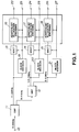
- Fig.1 is a block circuit diagram showing an illustrative arrangement of a high efficiency encoding device embodying the invention;
- Fig.2 illustrates the manner in which the device of Fig.1 divides signals along the time scale and along the frequency scale;
- Fig.3 is a block diagram showing an arrangement for finding a multi-channel bit-allocation parameter with the device shown in Fig.1;
- Fig.4 is a graph showing a manner of finding tonality;
- Fig.5 is a graph showing a manner of first bit allocation;
- Fig.6 is a graph showing a noise spectrum in the case of uniform allocation in the first bit allocation;
- Fig.7 is a graph showing an example of a noise spectrum by bit allocation for producing aural effects exhibiting dependency on the signal level and dependency on the frequency spectrum of information signals;
- Fig.8 is a graph showing the noise spectrum in the case of uniform allocation in a second bit allocation;
- Fig.9 is a graph showing an example of bit allocation for producing aural effects exhibiting dependency on the signal level and dependency on the frequency spectrum of information signals;
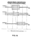
- Fig.10 shows a manner of finding a parameter for bit allocation which takes into account temporal characteristics of the information signals between channels;
- Fig.11 is a block circuit diagram showing an illustrative arrangement of a high efficiency decoding device embodying the invention;
- Fig.12 is a graph showing the relation between the amount of first bit allocation and channel-averaged tonality; and
- Fig.13 is a graph showing the relation between the amount of first bit allocation and channel-averaged time rate of change.
- A technique for high efficiency encoding of input digital signals, such as audio PCM signals, by sub-band coding (SBC), adaptive transform coding (ATC) and adaptive bit allocation (APC-AB), will now be explained in detail with reference to Fig.1.
- In a high efficiency encoding device shown in Fig.1, input digital signals are divided by a filter or the like into a plurality of frequency bands and orthogonally transformed from one frequency band to another to produce frequency-domain spectral data which is encoded by adaptive bit allocation on the basis of the critical bands which take into account the characteristics of the human aural sense as later explained. At this time, the critical bands are sub-divided into blocks as the frequency is increased. The frequency bands may naturally be of equal widths in the case of the non-block forming system which is performed with the aid of a filter or the like.
- Besides, in the present embodiment, the block size or the block length is adaptively changed prior to orthogonal transform depending on the input signals and a floating operation is performed on the basis of critical bands or of blocks sub-divided from the critical bands for higher frequencies. The critical bands mean the frequency bands which result from frequency division taking into account the characteristics of the human aural sense. That is, the critical band is the band proper to a narrow band noise which masks a pure tone having the same intensity as the noise and the frequency in the vicinity of the noise frequency. The total frequency range of from 0 to 22 kHz is divided into e.g. 25 critical bands which are selected so that the bandwidths become broader towards the higher frequencies. 25 critical bands.
- Referring to Fig.1, audio PCM signals having the frequency range of from 0 to 22 kHz, for example, are supplied to an
input terminal 10. The input signals are divided by a band-dividing filter 11, such as a QMF filter, into a band of from 0 to 11 kHz and a band of from 11 to 22 kHz. The frequency band of 0 to 11 kHz is divided by a band-dividingfilter 12 into a band of 0 to 5.5 kHz and a band of 5.5 to 112 kHz. The 11 kHz to 22 kHz signal from the filter 11 is supplied to a modified discrete cosine transform (MDCT)circuit 13, as an example of an orthogonal transform circuit, while the 5.5 kHz to 11 kHz signal from thefilter 12 is supplied to a modified discrete cosine transform (MDCT)circuit 14 and the 0 kHz to 5.5 kHz signal from thefilter 12 is supplied to a modified discrete cosine transform (MDCT)circuit 15 so as to be processed with MDCT. - Fig.2 shows a concrete example of a block size for the
MDCT circuits 13 to 15. In the concrete example of Fig.2, each of the three filter outputs has two block sizes for orthogonal transform. That is, for low frequency signals in the frequency band of 0 to 5.5 kHz and mid frequency signals in the frequency band of 5.5 to 11 kHz, each block is made up of 128 samples and 32 samples for the long block size (Fig.2A) and for the short block size (Fig.2B), respectively. On the other hand, for high frequency signals in the frequency band of 11 to 22 kHz, each block is made up of 256 samples and 32 samples for the long block size (Fig.2A) and for the short block size (Fig.2B), respectively. If the short block size is selected in this manner, the time resolution is increased towards the higher frequency and the number of kinds of the windows employed is decreased, with the number of samples of the orthogonal transform for each band remaining the same. - Returning to Fig.1, the frequency-domain spectral data or MDCT coefficients, obtained by the
MDCT circuits 13 to 15 by MDCT, are grouped according to the critical bands or, in a higher frequency range, according to small-sized blocks further divided from the critical bands, and transmitted to adaptive bitallocation encoding circuits allocation encoding circuits output terminals - As for the outputs of the
MDCT circuits 13 to 15 shown in Fig.1, the signal energies for the critical bands or those for the small-sized blocks sub-divided from the critical bands are found, such as by computing the roots of squared mean values of the respective amplitude values in the bands. The scale factor itself may naturally be employed for subsequent bit allocation. In such case, new energy computation becomes unnecessary resulting in saving in the hardware scale. The peak or mean values of the amplitude values may naturally be employed in place of the energies for the respective bands. - The operation of the adaptive bit allocation circuit is explained by referring to Fig.3. Although there are eight channels in the present embodiment, only
channels channel 1. Input information signals of thechannel 1 are supplied to aninput terminal 31. The input information signals are mapped from the time-domain signals on the frequency axis by a mapping function 32. If the filter is employed, the sub-band signals become time-domain samples. In the case of the orthogonal-transformed output, frequency-domain samples are produced. These samples are grouped into sets each consisting of plural samples by a block-formingfunction 33. If the filter is employed, plural time-domain samples are grouped together, while, in the case of the orthogonal-transformed output, plural frequency-domain samples are grouped together. In the embodiment of Fig.1, temporal changes of MDCT input time-domain signals during mapping are calculated by a temporalchange calculating function 44. - The samples grouped into the blocks each consisting of plural samples by the block-forming
function 33 are normalized by a normalizingfunction 37. The scale factor, a coefficient for normalization, is calculated by a scalefactor calculating function 35. From the calculated scale factor, the magnitude of tonality is calculated by atonality calculating function 36. The parameter found in this manner is employed for bit allocation in abit allocation function 38. If the number of bits which represents the MDCT coefficient and which is ready to be used for transmission or recording is assumed to be 800 kbps for the entire channels, the number of bits employed for the first bit allocation is determined in the present embodiment. - To this end, among the information concerning the signal spectrum, (a) the information concerning tonality and (b) the information concerning the temporal changes of the signal information, are employed.
- Referring first to the information concerning the tonality, the sum of absolute values of the differences between neighboring values of the signal spectral components divided by the number of signal spectral components is employed as an index. More precisely, the mean value of the differences between neighboring scale factor indices of the block-based scale factors for block floating is employed as the index. The scale factor index substantially corresponds to a logarithm of the scale factor. In the present embodiment, the amount of bits to be employed for the first bit allocation is associated with the value indicating the tonality and is set to a maximum value of 600 kbps and a minimum value of 300 kbps.
- The tonality is calculated in the following manner.


where
Tm = tonality of each channel
m = channel number
WLmax = maximum value of word length = 16
Ch = number of channels
SFn = scale factor index substantially corresponding to the logarithm of the peak value
n : band number for block floating
Tav : channel-averaged tonality
- The value of Tav found in this manner is associated with the first amount of bit allocation as shown in Fig.12.
- In the present embodiment, the proportion of distribution between allocation to the first bit allocation pattern and at least one other bit allocation to be appended thereto depends on the characteristics of temporal changes of the information signals. In the present embodiment, the time area in which the information signal amplitudes become abruptly larger is detected by comparing the peak values of the signal information for adjacent blocks for each time domain divided from the time block size for orthogonal transform to determine the proportion of distribution.
- The temporal rate of change is calculated in the following manner.


where
Vt : the sum for each channel of changes of the peak value of the time sub-block of each channel from a smaller value to a larger value, expressed in db
Vm : the magnitude of the largest one of the changes of the peak value of the time sub-block of each channel from a smaller value to a larger value, expressed in db, with the maximum value being limited to 30 db and expressed as Vmax
m : channel number
Ch : number of channels
Vab : channel-averaged changes of the peak value of the time sub-block of each channel from a smaller value to a larger value, expressed in db - The value of Vav found in this manner is associated with the amount of the first bit allocation as shown in Fig.13.
- Ultimately, the amount of the first bit allocation is found by the following equation:

where
B : ultimate value of the first bit allocation
Bf : the mount of bit allocation as found from Tav
Bt : the mount of bit allocation as found from Vav - After the amount of bits employed for the first bit allocation is determined in this manner, bit allocation is made for each channel for the first bit allocation.
- Various selection may be made depending on the signal properties. Adaptive bit allocation may naturally be made depending on the distribution of the scale factor on the frequency scale. In this case, effective bit allocation may be made by bit allocation between the channels depending on the distribution of the scale factor on the frequency scale for the totality of channels. In this case, if the signal information of plural channels is mixed in the same sound field to reach left and right ears as in the case of speakers, it may be assumed that effective masking is made by the mixed signals of the totality of the channels. Therefore, it is effective to perform bit allocation so that the same noise level is achieved for the respective channels. To this end, it suffices to perform bit allocation in proportion to the magnitude of the scale factor indices.


where
Bm : the amount of first bit allocation for each channel
B : the amount of first bit allocation for totality of channels
SFn = scale factor index substantially corresponding to the logarithm of the peak value
n = band number of block floating
m = channel number
S = sum of indices of scale factors of the totality of channels - Then, allocation of bits not employed in the first bit allocation is carried out. Various bit allocations are carried out herein.
- (1) Uniform allocation for the totality of sample values
The quantization noise spectrum for the bit allocation in this case is shown in Fig.6. Uniform noise level reduction may be made for the totality of the frequency bands. - (2) Bit allocation for realizing aural effects exhibiting the dependency on the signal level and the frequency spectrum of the signal information
An exemplary quantization noise spectrum for the bit allocation in this case is shown in Fig.7. In the present case, bit allocation is performed in dependence upon the spectrum of the information signals. In particular, bit allocation is performed so as to place emphasis on the low frequency side of the information signal spectrum to compensate for decreased masking effects on the low frequency side which occurs more pronouncedly than on the high frequency side. This is based on the non-symmetry of a masking curve which places emphasis on the low frequency of the signal spectrum to take account of the masking between neighboring critical bands. - Figs.8 and 9 illustrate the manner of bit allocation. In the case of low-tonality input signals where the signal spectrum is smooth over the entire frequency range, more bits are allocated to the first bit allocation as shown in Fig.8. Conversely, in the case of high tonality input signals, the amount of bits is decreased for the first bit allocation, as shown in Fig.9, whereas the amount of bits for the second bit allocation is increased, as shown in Fig.9, so that more bits are allocated to the signal spectrum having a larger level.
- In Figs. 7 and 9, second bit allocation is set so as to place emphasis on the low frequency side. In the present embodiment, there are a variety of patterns of bit allocation in which the amounts of bits of blocks of shorter time duration are distributed for the respective frequencies. In the present embodiment, above all, plural patterns of bit allocation are provided in which the rates of bit allocation are different for the mid to low frequency range and the high frequency range. Such a pattern is selected in which the smaller the signal magnitude, the lesser is the amount of bit allocation to the higher frequency side. In this manner, it becomes possible to take advantage of the loudness effects in which the sensitivity for the higher frequency is lowered for a smaller signal magnitude. Although the signal magnitude of the entire frequency range may be employed at this time for the signal magnitude, an output of a non-block forming frequency dividing circuit employing a filter or an MDCT output is utilized. Ultimately, the sum of the first bit allocation and the bit allocation annexed to the first bit allocation is found by a
bit allocation function 38 shown in Fig.3. - The present embodiment comprises, in addition to the above, a process of detecting the temporal change characteristics of the signals of the respective channels to change the amounts of bit allocation for the respective channels. An index representative of the temporal changes is found in the following manner.
- If there are eight channels as shown in Fig.10, the bit allocating time blocks, as time units of bit allocation of the information input signals of the respective channels, are temporally divided into four sub-blocks for each of which the peak value is found. The bits are distributed between the channels depending on the magnitude of the differences of the peak values of the sub-blocks which are changed from a smaller value to a larger value. If a sum total of C bits are available for bit allocation for the eight channels, and the differences of the peak values of the sub-blocks changed from a smaller value to a larger value are expressed as a, b, c, d, e, f, g and h db, bit allocation may be made by C*a/T, C*b/T, ...C*h/T bits, where T = a + b + c + d + e + f + g + h. The larger the rate of increase of the signal information the more the number of bits allocated to the channels. The ultimate bit allocation is made as the sum of the bits of the above-mentioned bit allocations.
- Besides, if the number of bits that may be used for each bit allocation is equal to C, it is possible to provide t bits as a countermeasure for the pre-echo. That is, if the C-t bits are the number of bits that may be used in the eight channels, and the magnitude of the differences of the peak values of the respective sub-blocks of each channel are expressed as a, b, c, d, e, f, g and h db, the bit allocation may be made by (C - t)*a/T, (C - t)*b/T, ....(C - t)*h/T bits.
- For one of the channels in which the pre-echo is of a maximum value, that is in which there exists the maximum value among a, b, c, d, e, f, g and h, the t-bits are allocated preferentially. Consequently, more t-bits are allocated to this channel so that pre-echo may be decreased significantly. In particular, when the present technique is used for a sound track of a cinefilm, in which main forward signals FR FL is critical, the t-bits may be allocated to one of them. Alternatively, the t-bits may be allocated to a woofer channel.
- Fig.11 shows a decoding circuit for decoding the high-efficiency coded signals. The quantized MDCT coefficients for the respective bands are supplied to input
terminals decoding circuits terminals decoding circuits circuits decoding circuits IMDCT circuits circuits 111, 112 into the entire range of signals and supplied to anoutput terminal 110. - It will be seen from above that the present embodiment provides a method of bit allocation which is aurally desirable for compression of temporally fluctuated information signals in a multi-channel system.
Claims (24)
- A high efficiency encoding method in which pre-set bit allocation is made for digital information signals of plural channels and the encoded information signals are obtained on the basis of the allocated bits, characterised in that the amount of bit allocation among the channels is performed based on temporal changes of the information signals of the respective channels.
- A method as claimed in claim 1, wherein the amounts of bit allocation among the channels are controlled depending on temporal changes of amplitude information of the digital information signals of the respective channels.
- A method as claimed in claim 2, wherein the amplitude information is the energy value, a peak value or a mean value of the digital information signals of the respective channels.
- A method as claimed in claim 1, wherein the amounts of bit allocation among the channels are controlled depending on temporal changes of a scale factor of the respective channels.
- A method as claimed in claim 4, wherein the amounts of bit allocation among the channels are controlled depending on temporal changes of the scale factor of the respective channels and temporal changes of word lengths caused by bit allocation among the channels.
- A method as claimed in claim 1, wherein the amounts of bit allocation among the channels are controlled depending on temporal changes of amplitude information of temporally neighboring plural blocks for the respective channels.
- A method as claimed in any one of claims 1 to 6, wherein the totality of bits employed for bit allocation is divided into a first bit allocation which depends on a pattern of indices indicating signal magnitude in small blocks obtained by sub-division with respect to time and frequency and at least one other bit allocation for aural effects appended to said first bit allocation.
- A method as claimed in claim 7, wherein the ratio of distribution between said first bit allocation and at least one other bit allocation is adaptively controlled depending on the information signals.
- A method as claimed in claim 8, wherein said ratio of distribution is controlled so that the larger the temporal changes in said information signals, the lesser becomes the ratio of distribution for said first bit allocation.
- A method as claimed in any one of claims 1 to 9, wherein an output of non-block forming frequency analysis is analyzed by block-forming frequency analysis, such as orthogonal transform, after the non-block forming frequency analysis, for producing samples in small blocks obtained by sub-division with respect to time and frequency.
- A method as claimed in claim 10, wherein the frequency band width of the non-block forming frequency analysis is the same at least the lower most range.
- A method as claimed in claim 10, wherein the frequency band width of the non-block forming frequency analysis is broader towards the higher frequency range at least the highest frequency range.
- A method as claimed in claim 10 or claim 11, wherein the non-block forming frequency analysis is performed by a filter (11, 12).
- A method as claimed in claim 13, wherein said filter (11, 12) is a polyphase quadrature filter.
- A method as claimed in claim 13 wherein said filter (11, 12) is a quadrature mirror filter.
- A method as claimed in any one of claims 10 to 15, wherein said block-forming frequency analysis is effected by MDCT.
- A method as claimed in any one of claims 10 to 16, wherein the block size for said block-forming frequency analysis is adaptively changed depending on temporal characteristics of input signals.
- A method as claimed in claim 17, wherein said block size is changed independently for each of at least two output bands of the non-block forming frequency analysis.
- A method as claimed in any one of claims 1 to 18, wherein the coded information is recorded on a recording medium.
- A method as claimed in claim 19, wherein said recording medium is a cinefilm, an optical disc, a magnetic tape or a magneto-optical disc.
- A recording medium on which coded information has been recorded by a method as claimed in claim 19 or claim 20.
- A method as claimed in any one of claims 1 to 18, wherein the coded information is transmitted on a digital information transmission channel.
- A method as claimed in claim 22, wherein said transmission channel is a digital information transmission channel.
- A high efficiency decoding method wherein recorded information or transmission signals recorded or transmitted by an encoding method as claimed in any one of claims 19 to 23 are decoded.
Applications Claiming Priority (3)
| Application Number | Priority Date | Filing Date | Title |
|---|---|---|---|
| JP1549293A JP3186292B2 (en) | 1993-02-02 | 1993-02-02 | High efficiency coding method and apparatus |
| JP15492/93 | 1993-02-02 | ||
| JP1549293 | 1993-02-02 |
Publications (3)
| Publication Number | Publication Date |
|---|---|
| EP0610007A2 true EP0610007A2 (en) | 1994-08-10 |
| EP0610007A3 EP0610007A3 (en) | 1995-07-12 |
| EP0610007B1 EP0610007B1 (en) | 2002-12-04 |
Family
ID=11890306
Family Applications (1)
| Application Number | Title | Priority Date | Filing Date |
|---|---|---|---|
| EP19940300502 Expired - Lifetime EP0610007B1 (en) | 1993-02-02 | 1994-01-24 | High efficiency encoding |
Country Status (6)
| Country | Link |
|---|---|
| US (1) | US5642111A (en) |
| EP (1) | EP0610007B1 (en) |
| JP (1) | JP3186292B2 (en) |
| KR (1) | KR100388730B1 (en) |
| CN (1) | CN1062097C (en) |
| DE (1) | DE69431816T2 (en) |
Cited By (4)
| Publication number | Priority date | Publication date | Assignee | Title |
|---|---|---|---|---|
| EP0665547A2 (en) * | 1994-01-28 | 1995-08-02 | Samsung Electronics Co., Ltd. | Encoding and decoding system |
| WO1996010870A1 (en) * | 1994-10-04 | 1996-04-11 | Alcatel Italia S.P.A. | Psychoacoustic audio-signal coding system and method |
| EP0716409A3 (en) * | 1994-12-08 | 1998-01-07 | Nec Corporation | Speech coding system |
| EP0825725A1 (en) * | 1996-08-20 | 1998-02-25 | Sony Corporation | Subband coding with adaptive bit allocation |
Families Citing this family (23)
| Publication number | Priority date | Publication date | Assignee | Title |
|---|---|---|---|---|
| US5765127A (en) * | 1992-03-18 | 1998-06-09 | Sony Corp | High efficiency encoding method |
| TW272341B (en) * | 1993-07-16 | 1996-03-11 | Sony Co Ltd | |
| KR960003628B1 (en) * | 1993-12-06 | 1996-03-20 | Lg전자주식회사 | Coding and decoding apparatus & method of digital signal |
| US5731767A (en) * | 1994-02-04 | 1998-03-24 | Sony Corporation | Information encoding method and apparatus, information decoding method and apparatus, information recording medium, and information transmission method |
| TW295747B (en) * | 1994-06-13 | 1997-01-11 | Sony Co Ltd | |
| JPH08190764A (en) * | 1995-01-05 | 1996-07-23 | Sony Corp | Method and device for processing digital signal and recording medium |
| JP3307138B2 (en) * | 1995-02-27 | 2002-07-24 | ソニー株式会社 | Signal encoding method and apparatus, and signal decoding method and apparatus |
| JPH0969781A (en) * | 1995-08-31 | 1997-03-11 | Nippon Steel Corp | Audio data encoding device |
| JPH09148937A (en) * | 1995-11-21 | 1997-06-06 | Sony Corp | Method and device for encoding processing and method and device for decoding processing |
| JPH1083623A (en) * | 1996-09-10 | 1998-03-31 | Sony Corp | Signal recording method, signal recorder, recording medium and signal processing method |
| KR100261254B1 (en) * | 1997-04-02 | 2000-07-01 | 윤종용 | Scalable audio data encoding/decoding method and apparatus |
| TW406480B (en) * | 1998-01-23 | 2000-09-21 | Sanyo Electric Co | Encoding and decoding apparatus |
| US6654189B1 (en) * | 1998-04-16 | 2003-11-25 | Sony Corporation | Digital-signal processing apparatus capable of adjusting the amplitude of a digital signal |
| US6353807B1 (en) * | 1998-05-15 | 2002-03-05 | Sony Corporation | Information coding method and apparatus, code transform method and apparatus, code transform control method and apparatus, information recording method and apparatus, and program providing medium |
| KR100548891B1 (en) * | 1998-06-15 | 2006-02-02 | 마츠시타 덴끼 산교 가부시키가이샤 | Audio coding apparatus and method |
| JP2000101439A (en) | 1998-09-24 | 2000-04-07 | Sony Corp | Information processing unit and its method, information recorder and its method, recording medium and providing medium |
| AU2001234971A1 (en) * | 2000-02-09 | 2001-08-20 | T. C. Cheng | Fast method for the forward and inverse mdct in audio coding |
| EP1332472B1 (en) * | 2000-11-10 | 2018-01-03 | British Telecommunications public limited company | Image characterisation |
| TW594674B (en) * | 2003-03-14 | 2004-06-21 | Mediatek Inc | Encoder and a encoding method capable of detecting audio signal transient |
| CN100339886C (en) * | 2003-04-10 | 2007-09-26 | 联发科技股份有限公司 | Coding device capable of detecting transient position of sound signal and its coding method |
| EP1671513B1 (en) | 2003-10-07 | 2013-07-24 | The Nielsen Company (US), LLC | Methods and apparatus to extract codes from a plurality of channels |
| KR20080053739A (en) * | 2006-12-11 | 2008-06-16 | 삼성전자주식회사 | Apparatus and method for encoding and decoding by applying to adaptive window size |
| US8204744B2 (en) | 2008-12-01 | 2012-06-19 | Research In Motion Limited | Optimization of MP3 audio encoding by scale factors and global quantization step size |
Citations (2)
| Publication number | Priority date | Publication date | Assignee | Title |
|---|---|---|---|---|
| EP0424016A2 (en) * | 1989-10-18 | 1991-04-24 | AT&T Corp. | Perceptual coding of audio signals |
| EP0446031A2 (en) * | 1990-03-07 | 1991-09-11 | Sony Corporation | Apparatus for encoding digital signals |
Family Cites Families (63)
| Publication number | Priority date | Publication date | Assignee | Title |
|---|---|---|---|---|
| US3349183A (en) * | 1963-10-29 | 1967-10-24 | Melpar Inc | Speech compression system transmitting only coefficients of polynomial representations of phonemes |
| US4184049A (en) * | 1978-08-25 | 1980-01-15 | Bell Telephone Laboratories, Incorporated | Transform speech signal coding with pitch controlled adaptive quantizing |
| CH645501GA3 (en) * | 1981-07-24 | 1984-10-15 | ||
| US4455649A (en) * | 1982-01-15 | 1984-06-19 | International Business Machines Corporation | Method and apparatus for efficient statistical multiplexing of voice and data signals |
| US4625286A (en) * | 1982-05-03 | 1986-11-25 | Texas Instruments Incorporated | Time encoding of LPC roots |
| US4535472A (en) * | 1982-11-05 | 1985-08-13 | At&T Bell Laboratories | Adaptive bit allocator |
| JPH07118159B2 (en) * | 1982-12-06 | 1995-12-18 | ソニー株式会社 | PCM signal recording method |
| DE3314384A1 (en) * | 1983-04-21 | 1984-10-25 | Siemens AG, 1000 Berlin und 8000 München | TRANSMISSION SYSTEM |
| CA1253255A (en) * | 1983-05-16 | 1989-04-25 | Nec Corporation | System for simultaneously coding and decoding a plurality of signals |
| JPH07118160B2 (en) * | 1983-06-18 | 1995-12-18 | ソニー株式会社 | Recording method of digital information signal |
| US4516241A (en) * | 1983-07-11 | 1985-05-07 | At&T Bell Laboratories | Bit compression coding with embedded signaling |
| GB8421498D0 (en) * | 1984-08-24 | 1984-09-26 | British Telecomm | Frequency domain speech coding |
| JPS61107818A (en) * | 1984-10-30 | 1986-05-26 | Nec Corp | Entropy coding system and its device |
| US5128963A (en) * | 1985-01-31 | 1992-07-07 | Sony Corporation | 3-mode PCM/DPCM/APCM maximizing dynamic range |
| US4885790A (en) * | 1985-03-18 | 1989-12-05 | Massachusetts Institute Of Technology | Processing of acoustic waveforms |
| US4748579A (en) * | 1985-08-14 | 1988-05-31 | Gte Laboratories Incorporated | Method and circuit for performing discrete transforms |
| EP0267344B1 (en) * | 1986-10-30 | 1993-09-01 | International Business Machines Corporation | Process for the multi-rate encoding of signals, and device for carrying out said process |
| AU604807B2 (en) * | 1986-12-19 | 1991-01-03 | Sony Corporation | Data recorder and method |
| US4903301A (en) * | 1987-02-27 | 1990-02-20 | Hitachi, Ltd. | Method and system for transmitting variable rate speech signal |
| US4882754A (en) * | 1987-08-25 | 1989-11-21 | Digideck, Inc. | Data compression system and method with buffer control |
| JP2618916B2 (en) * | 1987-09-10 | 1997-06-11 | 富士通株式会社 | Block size determination method for motion compensation |
| US4964166A (en) * | 1988-05-26 | 1990-10-16 | Pacific Communication Science, Inc. | Adaptive transform coder having minimal bit allocation processing |
| JPH0213135A (en) * | 1988-06-30 | 1990-01-17 | Sony Corp | Digital signal transmission equipment |
| JPH0783315B2 (en) * | 1988-09-26 | 1995-09-06 | 富士通株式会社 | Variable rate audio signal coding system |
| EP0370277A3 (en) * | 1988-11-24 | 1991-09-18 | Siemens Aktiengesellschaft | Sub-band transmission system |
| US5222189A (en) * | 1989-01-27 | 1993-06-22 | Dolby Laboratories Licensing Corporation | Low time-delay transform coder, decoder, and encoder/decoder for high-quality audio |
| US5142656A (en) * | 1989-01-27 | 1992-08-25 | Dolby Laboratories Licensing Corporation | Low bit rate transform coder, decoder, and encoder/decoder for high-quality audio |
| ES2119932T3 (en) * | 1989-01-27 | 1998-10-16 | Dolby Lab Licensing Corp | CODED SIGNAL FORMAT FOR HIGH QUALITY AUDIO SYSTEM ENCODER AND DECODER. |
| US5109417A (en) * | 1989-01-27 | 1992-04-28 | Dolby Laboratories Licensing Corporation | Low bit rate transform coder, decoder, and encoder/decoder for high-quality audio |
| US5016107A (en) * | 1989-05-09 | 1991-05-14 | Eastman Kodak Company | Electronic still camera utilizing image compression and digital storage |
| US4932062A (en) * | 1989-05-15 | 1990-06-05 | Dialogic Corporation | Method and apparatus for frequency analysis of telephone signals |
| JP2844695B2 (en) * | 1989-07-19 | 1999-01-06 | ソニー株式会社 | Signal encoding device |
| NL8902294A (en) * | 1989-09-14 | 1991-04-02 | Philips Nv | METHOD FOR MANUFACTURING A FIBER BUNDLE COMPOSED OF OPTICAL FIBERS |
| US5115240A (en) * | 1989-09-26 | 1992-05-19 | Sony Corporation | Method and apparatus for encoding voice signals divided into a plurality of frequency bands |
| FR2653280B1 (en) * | 1989-10-13 | 1992-01-10 | France Etat | BIT ALLOCATION DEVICE FOR TRANSFORMED AUDIO-DIGITAL SIGNAL, WITH ADAPTIVE QUANTIFICATION ON PSYCHO-AUDITIVE CRITERIA. |
| US5185800A (en) * | 1989-10-13 | 1993-02-09 | Centre National D'etudes Des Telecommunications | Bit allocation device for transformed digital audio broadcasting signals with adaptive quantization based on psychoauditive criterion |
| DE69028176T2 (en) * | 1989-11-14 | 1997-01-23 | Nec Corp | Adaptive transformation coding through optimal block length selection depending on differences between successive blocks |
| CN1062963C (en) * | 1990-04-12 | 2001-03-07 | 多尔拜实验特许公司 | Adaptive-block-lenght, adaptive-transform, and adaptive-window transform coder, decoder, and encoder/decoder for high-quality audio |
| JP2751564B2 (en) * | 1990-05-25 | 1998-05-18 | ソニー株式会社 | Digital signal coding device |
| JP3185214B2 (en) * | 1990-06-12 | 2001-07-09 | 日本電気株式会社 | Forward DCT and inverse DCT for improved DCT |
| JPH0472909A (en) * | 1990-07-13 | 1992-03-06 | Sony Corp | Quantization error reduction device for audio signal |
| JP3141241B2 (en) * | 1990-08-24 | 2001-03-05 | ソニー株式会社 | Disk recording device and disk reproducing device |
| JP3033156B2 (en) * | 1990-08-24 | 2000-04-17 | ソニー株式会社 | Digital signal coding device |
| US5235671A (en) * | 1990-10-15 | 1993-08-10 | Gte Laboratories Incorporated | Dynamic bit allocation subband excited transform coding method and apparatus |
| ZA921988B (en) * | 1991-03-29 | 1993-02-24 | Sony Corp | High efficiency digital data encoding and decoding apparatus |
| KR100312664B1 (en) * | 1991-03-29 | 2002-12-26 | 소니 가부시끼 가이샤 | Digital Signal Encoding Method |
| EP0506394A2 (en) * | 1991-03-29 | 1992-09-30 | Sony Corporation | Coding apparatus for digital signals |
| JP3134338B2 (en) * | 1991-03-30 | 2001-02-13 | ソニー株式会社 | Digital audio signal encoding method |
| JP3134337B2 (en) * | 1991-03-30 | 2001-02-13 | ソニー株式会社 | Digital signal encoding method |
| GB2258372B (en) * | 1991-08-02 | 1995-05-31 | Sony Corp | Apparatus for and methods of recording and/or reproducing digital data |
| ES2164640T3 (en) * | 1991-08-02 | 2002-03-01 | Sony Corp | DIGITAL ENCODER WITH DYNAMIC ASSIGNMENT OF QUANTIFICATION BITS. |
| JP3178026B2 (en) * | 1991-08-23 | 2001-06-18 | ソニー株式会社 | Digital signal encoding device and decoding device |
| JP3198550B2 (en) * | 1991-09-03 | 2001-08-13 | ソニー株式会社 | Compressed data recording method and compressed data recording / reproducing device |
| JP3158556B2 (en) * | 1991-09-27 | 2001-04-23 | ソニー株式会社 | Disk recording device and disk reproducing device |
| US5349549A (en) * | 1991-09-30 | 1994-09-20 | Sony Corporation | Forward transform processing apparatus and inverse processing apparatus for modified discrete cosine transforms, and method of performing spectral and temporal analyses including simplified forward and inverse orthogonal transform processing |
| DE69231369T2 (en) * | 1991-09-30 | 2001-03-29 | Sony Corp | Method and device for audio data compression |
| JP3141450B2 (en) * | 1991-09-30 | 2001-03-05 | ソニー株式会社 | Audio signal processing method |
| JP3134455B2 (en) * | 1992-01-29 | 2001-02-13 | ソニー株式会社 | High efficiency coding apparatus and method |
| JPH0629934A (en) * | 1992-07-10 | 1994-02-04 | Nippon Hoso Kyokai <Nhk> | Adaptive differential coding transmission method |
| JP3127600B2 (en) * | 1992-09-11 | 2001-01-29 | ソニー株式会社 | Digital signal decoding apparatus and method |
| JP3508146B2 (en) * | 1992-09-11 | 2004-03-22 | ソニー株式会社 | Digital signal encoding / decoding device, digital signal encoding device, and digital signal decoding device |
| JP3343962B2 (en) * | 1992-11-11 | 2002-11-11 | ソニー株式会社 | High efficiency coding method and apparatus |
| JP3185413B2 (en) * | 1992-11-25 | 2001-07-09 | ソニー株式会社 | Orthogonal transform operation and inverse orthogonal transform operation method and apparatus, digital signal encoding and / or decoding apparatus |
-
1993
- 1993-02-02 JP JP1549293A patent/JP3186292B2/en not_active Expired - Lifetime
-
1994
- 1994-01-19 US US08/184,471 patent/US5642111A/en not_active Expired - Lifetime
- 1994-01-24 EP EP19940300502 patent/EP0610007B1/en not_active Expired - Lifetime
- 1994-01-24 DE DE1994631816 patent/DE69431816T2/en not_active Expired - Lifetime
- 1994-01-25 KR KR1019940001254A patent/KR100388730B1/en not_active IP Right Cessation
- 1994-02-02 CN CN94101748A patent/CN1062097C/en not_active Expired - Lifetime
Patent Citations (2)
| Publication number | Priority date | Publication date | Assignee | Title |
|---|---|---|---|---|
| EP0424016A2 (en) * | 1989-10-18 | 1991-04-24 | AT&T Corp. | Perceptual coding of audio signals |
| EP0446031A2 (en) * | 1990-03-07 | 1991-09-11 | Sony Corporation | Apparatus for encoding digital signals |
Cited By (6)
| Publication number | Priority date | Publication date | Assignee | Title |
|---|---|---|---|---|
| EP0665547A2 (en) * | 1994-01-28 | 1995-08-02 | Samsung Electronics Co., Ltd. | Encoding and decoding system |
| EP0665547A3 (en) * | 1994-01-28 | 1996-01-10 | Samsung Electronics Co Ltd | Encoding and decoding system. |
| WO1996010870A1 (en) * | 1994-10-04 | 1996-04-11 | Alcatel Italia S.P.A. | Psychoacoustic audio-signal coding system and method |
| EP0716409A3 (en) * | 1994-12-08 | 1998-01-07 | Nec Corporation | Speech coding system |
| EP0825725A1 (en) * | 1996-08-20 | 1998-02-25 | Sony Corporation | Subband coding with adaptive bit allocation |
| US6097880A (en) * | 1996-08-20 | 2000-08-01 | Sony Corporation | Digital signal processing method, digital signal processing apparatus, digital signal recording method, digital signal recording apparatus, recording medium, digital signal transmission method and digital signal transmission apparatus |
Also Published As
| Publication number | Publication date |
|---|---|
| CN1062097C (en) | 2001-02-14 |
| KR100388730B1 (en) | 2003-09-13 |
| EP0610007B1 (en) | 2002-12-04 |
| JPH06232761A (en) | 1994-08-19 |
| CN1093843A (en) | 1994-10-19 |
| JP3186292B2 (en) | 2001-07-11 |
| US5642111A (en) | 1997-06-24 |
| DE69431816T2 (en) | 2003-09-11 |
| DE69431816D1 (en) | 2003-01-16 |
| EP0610007A3 (en) | 1995-07-12 |
Similar Documents
| Publication | Publication Date | Title |
|---|---|---|
| EP0610007B1 (en) | High efficiency encoding | |
| EP0545017B1 (en) | Data compression method and apparatus in which quantizing bits are allocated to a block in a present frame in response to the block in a past frame | |
| JP3134455B2 (en) | High efficiency coding apparatus and method | |
| US5737718A (en) | Method, apparatus and recording medium for a coder with a spectral-shape-adaptive subband configuration | |
| US5664056A (en) | Digital encoder with dynamic quantization bit allocation | |
| US5553193A (en) | Bit allocation method and device for digital audio signals using aural characteristics and signal intensities | |
| US5774844A (en) | Methods and apparatus for quantizing, encoding and decoding and recording media therefor | |
| US5758020A (en) | Methods and apparatus for encoding and decoding signals, methods for transmitting signals, and an information recording medium | |
| Iwadare et al. | A 128 kb/s hi-fi audio CODEC based on adaptive transform coding with adaptive block size MDCT | |
| EP0697665B1 (en) | Method and apparatus for encoding, transmitting and decoding information | |
| US5832426A (en) | High efficiency audio encoding method and apparatus | |
| US5642383A (en) | Audio data coding method and audio data coding apparatus | |
| JPH0846517A (en) | High efficiency coding and decoding system | |
| JP3088580B2 (en) | Block size determination method for transform coding device. | |
| US5950156A (en) | High efficient signal coding method and apparatus therefor | |
| KR100340368B1 (en) | High Efficiency Encoder, Decoder and Digital Data Derivation Method | |
| JP3134383B2 (en) | Method and apparatus for highly efficient encoding of digital data | |
| JP3134384B2 (en) | Encoding device and method | |
| JP3141853B2 (en) | Audio signal processing method | |
| JPH08237130A (en) | Method and device for signal coding and recording medium | |
| JPH0591062A (en) | Audio signal processing method |
Legal Events
| Date | Code | Title | Description |
|---|---|---|---|
| PUAI | Public reference made under article 153(3) epc to a published international application that has entered the european phase |
Free format text: ORIGINAL CODE: 0009012 |
|
| AK | Designated contracting states |
Kind code of ref document: A2 Designated state(s): DE FR GB |
|
| PUAL | Search report despatched |
Free format text: ORIGINAL CODE: 0009013 |
|
| AK | Designated contracting states |
Kind code of ref document: A3 Designated state(s): DE FR GB |
|
| 17P | Request for examination filed |
Effective date: 19951122 |
|
| 17Q | First examination report despatched |
Effective date: 20000510 |
|
| RIC1 | Information provided on ipc code assigned before grant |
Free format text: 7H 04B 1/66 A |
|
| RTI1 | Title (correction) |
Free format text: HIGH EFFICIENCY ENCODING |
|
| GRAG | Despatch of communication of intention to grant |
Free format text: ORIGINAL CODE: EPIDOS AGRA |
|
| RIC1 | Information provided on ipc code assigned before grant |
Free format text: 7H 04B 1/66 A |
|
| RTI1 | Title (correction) |
Free format text: HIGH EFFICIENCY ENCODING |
|
| GRAG | Despatch of communication of intention to grant |
Free format text: ORIGINAL CODE: EPIDOS AGRA |
|
| GRAH | Despatch of communication of intention to grant a patent |
Free format text: ORIGINAL CODE: EPIDOS IGRA |
|
| GRAH | Despatch of communication of intention to grant a patent |
Free format text: ORIGINAL CODE: EPIDOS IGRA |
|
| GRAA | (expected) grant |
Free format text: ORIGINAL CODE: 0009210 |
|
| AK | Designated contracting states |
Kind code of ref document: B1 Designated state(s): DE FR GB |
|
| REG | Reference to a national code |
Ref country code: GB Ref legal event code: FG4D |
|
| REF | Corresponds to: |
Ref document number: 69431816 Country of ref document: DE Date of ref document: 20030116 |
|
| ET | Fr: translation filed | ||
| PLBE | No opposition filed within time limit |
Free format text: ORIGINAL CODE: 0009261 |
|
| STAA | Information on the status of an ep patent application or granted ep patent |
Free format text: STATUS: NO OPPOSITION FILED WITHIN TIME LIMIT |
|
| 26N | No opposition filed |
Effective date: 20030905 |
|
| REG | Reference to a national code |
Ref country code: GB Ref legal event code: 746 Effective date: 20120703 |
|
| REG | Reference to a national code |
Ref country code: DE Ref legal event code: R084 Ref document number: 69431816 Country of ref document: DE Effective date: 20120614 |
|
| PGFP | Annual fee paid to national office [announced via postgrant information from national office to epo] |
Ref country code: FR Payment date: 20130213 Year of fee payment: 20 Ref country code: GB Payment date: 20130122 Year of fee payment: 20 Ref country code: DE Payment date: 20130122 Year of fee payment: 20 |
|
| REG | Reference to a national code |
Ref country code: DE Ref legal event code: R071 Ref document number: 69431816 Country of ref document: DE |
|
| REG | Reference to a national code |
Ref country code: GB Ref legal event code: PE20 Expiry date: 20140123 |
|
| PG25 | Lapsed in a contracting state [announced via postgrant information from national office to epo] |
Ref country code: GB Free format text: LAPSE BECAUSE OF EXPIRATION OF PROTECTION Effective date: 20140123 Ref country code: DE Free format text: LAPSE BECAUSE OF EXPIRATION OF PROTECTION Effective date: 20140125 |