EP0582870B1 - A variable distention angioplasty balloon assembly - Google Patents
A variable distention angioplasty balloon assembly Download PDFInfo
- Publication number
- EP0582870B1 EP0582870B1 EP93111706A EP93111706A EP0582870B1 EP 0582870 B1 EP0582870 B1 EP 0582870B1 EP 93111706 A EP93111706 A EP 93111706A EP 93111706 A EP93111706 A EP 93111706A EP 0582870 B1 EP0582870 B1 EP 0582870B1
- Authority
- EP
- European Patent Office
- Prior art keywords
- balloon
- assembly
- balloons
- modulus
- variable
- Prior art date
- Legal status (The legal status is an assumption and is not a legal conclusion. Google has not performed a legal analysis and makes no representation as to the accuracy of the status listed.)
- Expired - Lifetime
Links
Images
Classifications
-
- A—HUMAN NECESSITIES
- A61—MEDICAL OR VETERINARY SCIENCE; HYGIENE
- A61M—DEVICES FOR INTRODUCING MEDIA INTO, OR ONTO, THE BODY; DEVICES FOR TRANSDUCING BODY MEDIA OR FOR TAKING MEDIA FROM THE BODY; DEVICES FOR PRODUCING OR ENDING SLEEP OR STUPOR
- A61M25/00—Catheters; Hollow probes
- A61M25/10—Balloon catheters
- A61M25/104—Balloon catheters used for angioplasty
-
- A—HUMAN NECESSITIES
- A61—MEDICAL OR VETERINARY SCIENCE; HYGIENE
- A61M—DEVICES FOR INTRODUCING MEDIA INTO, OR ONTO, THE BODY; DEVICES FOR TRANSDUCING BODY MEDIA OR FOR TAKING MEDIA FROM THE BODY; DEVICES FOR PRODUCING OR ENDING SLEEP OR STUPOR
- A61M25/00—Catheters; Hollow probes
- A61M25/10—Balloon catheters
- A61M25/1011—Multiple balloon catheters
- A61M2025/1013—Multiple balloon catheters with concentrically mounted balloons, e.g. being independently inflatable
-
- A—HUMAN NECESSITIES
- A61—MEDICAL OR VETERINARY SCIENCE; HYGIENE
- A61M—DEVICES FOR INTRODUCING MEDIA INTO, OR ONTO, THE BODY; DEVICES FOR TRANSDUCING BODY MEDIA OR FOR TAKING MEDIA FROM THE BODY; DEVICES FOR PRODUCING OR ENDING SLEEP OR STUPOR
- A61M25/00—Catheters; Hollow probes
- A61M25/10—Balloon catheters
- A61M2025/1043—Balloon catheters with special features or adapted for special applications
- A61M2025/1075—Balloon catheters with special features or adapted for special applications having a balloon composed of several layers, e.g. by coating or embedding
Definitions
- This invention relates to a dilatation balloon assembly and particularly to a novel improvement in variable distention angioplasty balloon assembly.
- the Wallace U.S. Patent No. 3,045,677 discloses a balloon catheter adapted for insertion into a body cavity, such as a bladder, that includes two balloon portions integral with a catheter and having a tube extending over the balloon portions and cemented at opposite ends and to a shaft of the catheter.
- the Shockey et al U.S. Patent No. 4,994,033 discloses an intravascular drug delivery dilatation catheter including an inner expander member having micropores therethrough and an outer expander member also having micropores therethrough.
- the balloon assembly has two different fixed working diameters for dilating an anatomical stricture, one of the working diameters corresponds to the maximum inflated diameter of the inner balloon plus the uninflated thickness of the outer balloon over the first balloon and the other of the working diameters corresponds to the maximum inflated diameter of the outer balloon.
- a variable distention rate of the assembly dependent on its diameter is not provided.
- an object of the present invention to provide an improved angioplasty balloon assembly which allows a precise dilating of an anatomical stricture with minimal chances of bursting.
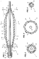
- FIG. 1 of the drawings is an axial longitudinal sectional view of a variable distention angioplasty balloon assembly in a partially dilated condition, with a catheter aligned and enclosed therein.
- FIG. 2 of the drawings is a diametrical sectional view through the assembly in FIG. 1 and is taken along line 2-2 of FIG. 1.
- FIG. 3 of the drawings is a diametrical sectional view through the assembly in FIG. 1 and is taken along line 3-3 of FIG. 1.
- FIG. 4 of the drawings is a diametrical sectional view through the assembly in FIG. 1 and is taken along line 4-4 of FIG. 1.
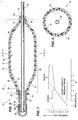
- FIG. 5 of the drawings is an axial longitudinal sectional view, similar to the view in FIG. 1, illustrating the balloon assembly thereof in a fully expanded condition, with a catheter aligned therein.
- FIG. 6 of the drawings is a diametrical sectional view of FIG. 5 and is taken along the line 6-6 in FIG. 5.
- FIG. 7 of the drawings is a graph illustrating the predicted pressure and diameter characteristic curve of the balloon assembly in FIG. 1.
- FIG. 1 illustrated in FIG. 1 is a variable distention angioplasty balloon assembly 10, for insertion into and dilation of an anatomical stricture in a blood vessel or other body cavity.
- the multi-layer balloon assembly 10 includes an inner elongated, inflatable balloon 12 having a distal portion 14, a proximal portion 16 and an intermediate portion 18 therebetween and defining therein a first chamber 19.
- the inner balloon 12 has a pre-selected first modulus of elasticity (Young's modulus of elasticity) thereby having a predicted fixed-linear pressure-diameter characteristic or relationship as illustrated in Region A in FIG. 7.
- the assembly 10 further includes an outer elongated, inflatable balloon 20 having a distal portion 22, a proximal portion 24 and an intermediate portion 26 therebetween positioned around the first balloon 12 and defining a second chamber 27 between the balloons.
- the outer balloon 20 has a second modulus of elasticity (Young's modulus of elasticity) different from the inner balloon 12.
- the outer balloon 20 second modulus of elasticity has a predicted fixed-linear pressure-diameter characteristic or relationship as illustrated in Region B in FIG. 7.
- the inner balloon 12 is substantially enclosed by and longitudinally co-extensive with the outer balloon 20. As shown in FIG. 7, the predicted first modulus of elasticity of the inner balloon 12 is less than the second modulus of elasticity of the outer balloon 20.
- the balloons 12 and 20 are substantially impermeate thereby having the predicted characteristics illustrated in FIG. 7.
- the inner and outer balloons 12 and 20 distal portions 14 and 22 include port sections 15 and 23 and the proximal portions 16 and 24 include port sections 17 and 25, respectively, for allowing a catheter and further means for dilating the assembly 10.
- the distal port sections 15 and 23 are adhesively sealed or preferably heat sealed to each other, for a good seal and are attached to a catheter.
- the proximal port sections 17 and 25 are adhesively sealed or preferably heat sealed to each other for improved seals, and attached to other means, such as a hub or an intermediate section for inflating or dilating assembly 10.
- the first chamber 19 of the inner balloon 12 and the second chamber 27 of the outer balloon 20 define a variable dilation structure 28 (dashed rectangle in FIG. 1) for dilating an anatomical stricture.
- the variable dilation structure 28 with the predicted variable characteristic curve in FIG. 7 has a first linear diameter and pressure characteristic curve (solid line in Region A) defined by the modulus of elasticity of the inner balloon 12 and a second linear diameter and pressure characteristic curve (solid line in Region B) defined by the modulus of elasticity of the outer balloon 20.
- the variable characteristic curve includes a first diameter and pressure characteristic in Region A, defined by the modulus of elasticity of the inner balloon 12 and a second diameter and pressure characteristic curve in Region B, defined by the modulus of elasticity of the outer balloon 20.
- the assembly 10 allows a physician for example, to dilate an anatomical stricture with the use of the inner balloon 12 characteristic curve alone, or the combination of the characteristic with the outer balloon 20 characteristic curve for a slightly larger diameter with a smaller incremental increase in pressure, without the need of withdrawing a narrow first balloon in a mono-layer balloon assembly and reinserting a wider second balloon, with all the inherent risks associated with reinserting a second balloon.
- the inner balloon 12 is more elastic and has the first characteristics in FIG. 7, and the outer balloon 20 is less elastic and has the second characteristic curve.
- the combination of first and second characteristic curve in dilation structure 28 advantageously gives a physician increased flexibility, by allowing him or her to increase the pressure in the desired working pressure range in FIG. 7, with a smaller increase in diameter of structure 28, for more precise dilating of an anatomical stricture with minimal chances of bursting.
- mono-layer balloon assemblies which have distention properties which are not variable and which behave similar to those in first characteristic curve alone (solid and dashed line in FIG. 7) or second characteristic curve alone, along their entire range in FIG. 7.
- first characteristic curve alone solid and dashed line in FIG. 7
- second characteristic curve alone along their entire range in FIG. 7.
- the assembly 10 provides a clinician the opportunity to increase the pressure in the desired working pressure range without a significant diameter increase, while working in a safe working pressure range in FIG. 7.
- the assembly 10 provides a clinician with the ability to vary the inflated structure 28 diameter within a narrow-safe pressure range, and further allows a pressure increase with less size increase, than is provided by a conventional mono-layer balloon, resulting in improved substantially uniform radial pressure circumferentially about, along the length and diameter of the dilation structure 28 in proximity to the stricture being dilated. Further, the assembly 10 provides the benefit of eliminating the need to change to a second catheter with a larger balloon diameter when a larger dilating diameter is required in mono-layer assemblies, for example.
- a further advantage of assembly 10, is that the structure 28 includes the outer balloon 20 enclosing the inner balloon 12, thereby minimizing the possibility of rupture of structure 28. If the inner balloon 12 should rupture, as can happen during inflation, the assembly 10 has a reduced potential for vessel damage and minimal chances of loosing a piece of the ruptured balloon in the bloodstream, because such pieces will be collected in the outer balloon 20.
- the outer balloon 20 and the inner balloon 12 reinforce the variable dilation structure 28 so as to minimize the possibility of rupture of balloons 12 and 20 individually, and also provides a more durable and resilient structure 28 which can withstand greater inflation pressures, and provide an improved degree of protection when expanded, inserted or removed, or when deploying a stent, which many times in a single balloon assembly has a tendency to puncture or burst.
- the assembly 10 can be used for many types of dilation products, such as angioplasty, valvuloplasty, urethroplasty, salpingoplasty, and the like.
- the assembly 10 can be attached to an over the wire, fixed wire, hybrid over the wire or rapid exchange monorail type dilation system.
- the assembly 10 is particularly suited for dilating blood vessels within an area of stenosis.
- the assembly 10 can also be used to deploy a stent in a body cavity or blood vessel (not shown in the drawings).
- the stent is received around the assembly 10 structure 28, and the entire dilating structure 28 and the stent is received within a body cavity.
- the elasticity of the balloons 12 and 20 exert radially outwardly pressure to and against a stent (not shown in the FIGS.), to expand the stent as desired against an appropriate body cavity.
- the dilating structure 28 is deflated and removed.
- the inner balloon 12 and the outer balloon 20 are tubular, annular, flexible and expandable and comprise a polymeric material.
- the inner and outer balloons 12 and 20 comprise at least one polymeric material selected from the group consisting of polyolefins, copolymers of polyolefins, polyamides, polyvinyl chloride, polyethylene terephthalate, and combinations and permutations thereof more preferably a polyamide such as nylon (registered trademark) because of its desirable properties, such as elasticity, durability, formability, manufacturability, etc.
- the inner and outer balloons 12 and 20 comprise a polyamide such as 70D nylon and 75D nylon (registered trademark), respectively, for desirable properties.
- the balloon assembly 10 further includes a hub 36 having a first member 38 with a port 40 and an annular and tubular intermediate section 42 for inflating the inner balloon 12 until it reaches the outer balloon 20, and thereafter both balloons 12 and 20.
- the hub 36 is attached to and circumferentially around a proximal portion of the intermediate section 42, and the intermediate section 42 at the other end is attached to and circumferentially within a portion of the proximal portions 16 and 24 of the balloons 12 and 20 defining the dilation structure 28.
- the assembly 10 further includes an inflating device for inflating balloons 12 and 20, connected to member 38 (not shown in the drawings).
- the dilating structure 28 further includes the intermediate portions 18 and 26 of the inner and outer balloons 12 and 20 forming a first inclined section 46, a middle section 48 and a second inclined section 50.
- the first inclined section 46 is axially-adjacent to the proximal portions 16 and 24 of the balloons 12 and 20, respectively
- the second inclined section 50 is axially-adjacent to the distal portions 14 and 22 of the balloons 12 and 20, respectively.
- the first and second inclined sections 46 and 50 extend outwardly at an angle ranging from about 5° to about 85° when dilated, with respect to an axial or elongate axis extending through the center of the assembly 10 in FIG. 5, and preferably ranging from about 15° to 60°, and most preferably about 45° for a smooth and gradual increase and decrease in diameter for improved durability and flexibility.
- the balloon assembly 10 includes a catheter 52 positioned and enclosed in the inner balloon 12 in alignment with the elongate axis for facilitating the insertion of the dilation structure 28 in a body cavity.
- the balloon assembly 10 further includes a path 56 (dashed line) from the hub 36 port 40 to the proximal portion 16 of the inner balloon 12 for inflating the balloons 12 and 20.
- the path 56 provides a means for delivery of dilatation fluid, such as a de-enzo fluid to structure 28.
- the path 56 also receives the catheter 52 partially therealong.
- the first modulus of elasticity of the inner balloon 12 can range widely.
- the modulus of elasticity ranges from about 2% 9,87 ⁇ 10 -6 Pa (atmosphere (atm)) to about 5% 9,87 ⁇ 10 -6 Pa (atm), and typically is about 3.5% 9,87 ⁇ 10 -6 Pa (atm).
- the second modulus of elasticity of the outer balloon 20 can range widely. Preferably, it ranges from about 0.5% 9,87 ⁇ 10 -6 Pa (atm) to about 2% 9,87 ⁇ 10 -6 Pa (atm), and typically is about 1% / atm.
- the intermediate portions 18 and 26 of the balloons 12 and 20 in FIG. 5 are substantially adjacent and have a substantially similar dilation diameter therealong, with the diameter of the inner balloon 12 being slightly smaller than that of the outer balloon 20, for providing a substantially uniform and durable circumferential and outward radial pressure to the stricture being dilated.
- the length of the dilation structure 28 can range widely depending on the intended application. In one embodiment, the length ranges from about 50 mm to about 10 mm, preferably about 30 mm to about 10 mm, and typically about 20 mm in length for angioplasty dilation products.
- the diameter of the structure 28 can range widely depending on the intended application, preferably the diameter ranges from about 30 mm to about 1 mm, and more preferably from about 1 mm to about 5 mm in diameter when used as an angioplasty dilation product.
- each balloon 12 and 20 each have wall thicknesses that can vary widely depending on the material utilized.
- each balloon 12 and 20 has a wall thickness of about 50,8 ⁇ 10 -3 mm (2 mils) or less, preferably about 25,4 ⁇ 10 -3 mm (1 mil) or less when utilizing a polymeric material.
- One preferred material is a polyamide, for elasticity, durability, strength, and minimal volume and surface area for ease of insertion and withdrawal into and out of a body cavity.
- a physician utilizing dilation structure 28 performs the following procedure. First, a physician inserts structure 28 about the stricture to be dilated, such as in an area of stenosis. Next, he or she dilates dilation structure 28 in the stricture. Initially the inner balloon 12 diameter grows or increases independently until it reaches or touches the walls of the outer balloon 20 in FIGS. 5 and 6 (see the first characteristic curve in FIG. 7). Thereafter, as the pressure is further increased, the diameter of the dilation structure 28 increases more slowly, which is dependant upon the modulus of elasticity of the outer balloon 20.
- the dilation step can include two stages, including following the solid line in Region A alone and thereafter, if needed, following the solid line in Region B.
- the dilation structure 28 diameter increases linearly and fairly rapidly as indicated in first characteristic curve.
- Region B the inner balloon 12 reaches the outer balloon 20, as shown in FIG. 6, and the diameter increases more slowly but still linearly, as indicated in the second characteristic curve (solid line).
- the balloons 12 and 20 improve resistance to rupture and provide a smooth circumferential surface and radial pressure along the middle section 48 of the dilation structure 28 about the stricture being dilated. Thereafter, the apparatus 10 is deflated and removed.
Description
- This invention relates to a dilatation balloon assembly and particularly to a novel improvement in variable distention angioplasty balloon assembly.
- Heretofore various angioplasty balloon assemblies have been proposed. Examples of such assemblies are disclosed in the following U.S. Patents:
U.S.Patent No. Patentee 3,045,677 F. J. Wallace 4,994,033 Shockey, et al. - The Wallace U.S. Patent No. 3,045,677, discloses a balloon catheter adapted for insertion into a body cavity, such as a bladder, that includes two balloon portions integral with a catheter and having a tube extending over the balloon portions and cemented at opposite ends and to a shaft of the catheter.
- The Shockey et al U.S. Patent No. 4,994,033, discloses an intravascular drug delivery dilatation catheter including an inner expander member having micropores therethrough and an outer expander member also having micropores therethrough.
- From document EP-A-261 831, which is used as a basis for the preamble of
claim 1, a variable distention angioplasty balloon assembly for insertion into a blood vessel is known, comprising an inner elongated, inflatable balloon having a distal portion, a proximal portion and an intermediate portion therebetween and defining therein a first chamber; an outer elongated, inflatable balloon having a distal portion, a proximal portion and an intermediate portion therebetween, positioned around said inner balloon and defining between the balloons a second chamber, said inner balloon being substantially enclosed by said outer balloon; whereby said first chamber of said inner balloon and said second chamber of said outer balloon define a variable dilation structure for dilating an anatomical stricture. The balloon assembly has two different fixed working diameters for dilating an anatomical stricture, one of the working diameters corresponds to the maximum inflated diameter of the inner balloon plus the uninflated thickness of the outer balloon over the first balloon and the other of the working diameters corresponds to the maximum inflated diameter of the outer balloon. A variable distention rate of the assembly dependent on its diameter is not provided. - It is, therefore, an object of the present invention to provide an improved angioplasty balloon assembly which allows a precise dilating of an anatomical stricture with minimal chances of bursting.
- The technical problem is solved by an balloon assembly in accordance with
claim 1. - Improvements of this balloon assembly are the subject-matter of the dependent claims.
- FIG. 1 of the drawings is an axial longitudinal sectional view of a variable distention angioplasty balloon assembly in a partially dilated condition, with a catheter aligned and enclosed therein.
- FIG. 2 of the drawings is a diametrical sectional view through the assembly in FIG. 1 and is taken along line 2-2 of FIG. 1.
- FIG. 3 of the drawings is a diametrical sectional view through the assembly in FIG. 1 and is taken along line 3-3 of FIG. 1.
- FIG. 4 of the drawings is a diametrical sectional view through the assembly in FIG. 1 and is taken along line 4-4 of FIG. 1.
- FIG. 5 of the drawings is an axial longitudinal sectional view, similar to the view in FIG. 1, illustrating the balloon assembly thereof in a fully expanded condition, with a catheter aligned therein.
- FIG. 6 of the drawings is a diametrical sectional view of FIG. 5 and is taken along the line 6-6 in FIG. 5.
- FIG. 7 of the drawings is a graph illustrating the predicted pressure and diameter characteristic curve of the balloon assembly in FIG. 1.
- Referring now to the drawings in greater detail, illustrated in FIG. 1 is a variable distention
angioplasty balloon assembly 10, for insertion into and dilation of an anatomical stricture in a blood vessel or other body cavity. - The
multi-layer balloon assembly 10 includes an inner elongated,inflatable balloon 12 having adistal portion 14, aproximal portion 16 and anintermediate portion 18 therebetween and defining therein afirst chamber 19. Theinner balloon 12 has a pre-selected first modulus of elasticity (Young's modulus of elasticity) thereby having a predicted fixed-linear pressure-diameter characteristic or relationship as illustrated in Region A in FIG. 7. - The
assembly 10 further includes an outer elongated,inflatable balloon 20 having adistal portion 22, aproximal portion 24 and anintermediate portion 26 therebetween positioned around thefirst balloon 12 and defining asecond chamber 27 between the balloons. Theouter balloon 20 has a second modulus of elasticity (Young's modulus of elasticity) different from theinner balloon 12. Theouter balloon 20 second modulus of elasticity has a predicted fixed-linear pressure-diameter characteristic or relationship as illustrated in Region B in FIG. 7. Theinner balloon 12 is substantially enclosed by and longitudinally co-extensive with theouter balloon 20. As shown in FIG. 7, the predicted first modulus of elasticity of theinner balloon 12 is less than the second modulus of elasticity of theouter balloon 20. - In one embodiment, the
balloons outer balloons distal portions port sections proximal portions port sections assembly 10. - In one embodiment, the
distal port sections proximal port sections assembly 10. - The
first chamber 19 of theinner balloon 12 and thesecond chamber 27 of theouter balloon 20 define a variable dilation structure 28 (dashed rectangle in FIG. 1) for dilating an anatomical stricture. Thevariable dilation structure 28 with the predicted variable characteristic curve in FIG. 7, has a first linear diameter and pressure characteristic curve (solid line in Region A) defined by the modulus of elasticity of theinner balloon 12 and a second linear diameter and pressure characteristic curve (solid line in Region B) defined by the modulus of elasticity of theouter balloon 20. - The variable characteristic curve includes a first diameter and pressure characteristic in Region A, defined by the modulus of elasticity of the
inner balloon 12 and a second diameter and pressure characteristic curve in Region B, defined by the modulus of elasticity of theouter balloon 20. - In use, the
assembly 10 allows a physician for example, to dilate an anatomical stricture with the use of theinner balloon 12 characteristic curve alone, or the combination of the characteristic with theouter balloon 20 characteristic curve for a slightly larger diameter with a smaller incremental increase in pressure, without the need of withdrawing a narrow first balloon in a mono-layer balloon assembly and reinserting a wider second balloon, with all the inherent risks associated with reinserting a second balloon. - More particularly, the
inner balloon 12 is more elastic and has the first characteristics in FIG. 7, and theouter balloon 20 is less elastic and has the second characteristic curve. The combination of first and second characteristic curve indilation structure 28 advantageously gives a physician increased flexibility, by allowing him or her to increase the pressure in the desired working pressure range in FIG. 7, with a smaller increase in diameter ofstructure 28, for more precise dilating of an anatomical stricture with minimal chances of bursting. - For example, mono-layer balloon assemblies are known which have distention properties which are not variable and which behave similar to those in first characteristic curve alone (solid and dashed line in FIG. 7) or second characteristic curve alone, along their entire range in FIG. 7. In such mono-layer assemblies, it is possible to obtain significant dimensional variability only with an undesirable increase in size beyond the desired working pressure range, for example, the dashed line in FIG. 7. In contrast, the
assembly 10 provides a clinician the opportunity to increase the pressure in the desired working pressure range without a significant diameter increase, while working in a safe working pressure range in FIG. 7. Advantageously, theassembly 10 provides a clinician with the ability to vary the inflatedstructure 28 diameter within a narrow-safe pressure range, and further allows a pressure increase with less size increase, than is provided by a conventional mono-layer balloon, resulting in improved substantially uniform radial pressure circumferentially about, along the length and diameter of thedilation structure 28 in proximity to the stricture being dilated. Further, theassembly 10 provides the benefit of eliminating the need to change to a second catheter with a larger balloon diameter when a larger dilating diameter is required in mono-layer assemblies, for example. - A further advantage of
assembly 10, is that thestructure 28 includes theouter balloon 20 enclosing theinner balloon 12, thereby minimizing the possibility of rupture ofstructure 28. If theinner balloon 12 should rupture, as can happen during inflation, theassembly 10 has a reduced potential for vessel damage and minimal chances of loosing a piece of the ruptured balloon in the bloodstream, because such pieces will be collected in theouter balloon 20. Theouter balloon 20 and theinner balloon 12 reinforce thevariable dilation structure 28 so as to minimize the possibility of rupture ofballoons resilient structure 28 which can withstand greater inflation pressures, and provide an improved degree of protection when expanded, inserted or removed, or when deploying a stent, which many times in a single balloon assembly has a tendency to puncture or burst. - The
assembly 10 can be used for many types of dilation products, such as angioplasty, valvuloplasty, urethroplasty, salpingoplasty, and the like. Theassembly 10 can be attached to an over the wire, fixed wire, hybrid over the wire or rapid exchange monorail type dilation system. Theassembly 10 is particularly suited for dilating blood vessels within an area of stenosis. - The
assembly 10 can also be used to deploy a stent in a body cavity or blood vessel (not shown in the drawings). The stent is received around theassembly 10structure 28, and the entiredilating structure 28 and the stent is received within a body cavity. When theassembly 10 is used in conjunction with a stent, the elasticity of theballoons structure 28 is deflated and removed. - In one embodiment, the
inner balloon 12 and theouter balloon 20 are tubular, annular, flexible and expandable and comprise a polymeric material. - In one preferred embodiment, the inner and
outer balloons outer balloons - In one embodiment, the
balloon assembly 10 further includes ahub 36 having afirst member 38 with aport 40 and an annular and tubularintermediate section 42 for inflating theinner balloon 12 until it reaches theouter balloon 20, and thereafter bothballoons hub 36 is attached to and circumferentially around a proximal portion of theintermediate section 42, and theintermediate section 42 at the other end is attached to and circumferentially within a portion of theproximal portions balloons dilation structure 28. Theassembly 10 further includes an inflating device for inflatingballoons - Referring to FIG. 5, the dilating
structure 28 further includes theintermediate portions outer balloons inclined section 46, amiddle section 48 and a secondinclined section 50. The firstinclined section 46 is axially-adjacent to theproximal portions balloons inclined section 50 is axially-adjacent to thedistal portions balloons inclined sections assembly 10 in FIG. 5, and preferably ranging from about 15° to 60°, and most preferably about 45° for a smooth and gradual increase and decrease in diameter for improved durability and flexibility. - In one embodiment, the
balloon assembly 10 includes acatheter 52 positioned and enclosed in theinner balloon 12 in alignment with the elongate axis for facilitating the insertion of thedilation structure 28 in a body cavity. - The
balloon assembly 10 further includes a path 56 (dashed line) from thehub 36port 40 to theproximal portion 16 of theinner balloon 12 for inflating theballoons path 56 provides a means for delivery of dilatation fluid, such as a de-enzo fluid to structure 28. In one embodiment, thepath 56 also receives thecatheter 52 partially therealong. - The first modulus of elasticity of the
inner balloon 12 can range widely. In one embodiment, the modulus of elasticity ranges from about 2% 9,87·10-6 Pa (atmosphere (atm)) to about 5% 9,87·10-6 Pa (atm), and typically is about 3.5% 9,87·10-6 Pa (atm). Similarly, the second modulus of elasticity of theouter balloon 20 can range widely. Preferably, it ranges from about 0.5% 9,87·10-6 Pa (atm) to about 2% 9,87·10-6 Pa (atm), and typically is about 1% / atm. - When
balloon assembly 10 is fully inflated in the B Region in FIG. 7, theintermediate portions balloons inner balloon 12 being slightly smaller than that of theouter balloon 20, for providing a substantially uniform and durable circumferential and outward radial pressure to the stricture being dilated. - The length of the
dilation structure 28 can range widely depending on the intended application. In one embodiment, the length ranges from about 50 mm to about 10 mm, preferably about 30 mm to about 10 mm, and typically about 20 mm in length for angioplasty dilation products. Similarly, the diameter of thestructure 28 can range widely depending on the intended application, preferably the diameter ranges from about 30 mm to about 1 mm, and more preferably from about 1 mm to about 5 mm in diameter when used as an angioplasty dilation product. - The
balloons balloon - In use, a physician utilizing
dilation structure 28 performs the following procedure. First, a physician insertsstructure 28 about the stricture to be dilated, such as in an area of stenosis. Next, he or she dilatesdilation structure 28 in the stricture. Initially theinner balloon 12 diameter grows or increases independently until it reaches or touches the walls of theouter balloon 20 in FIGS. 5 and 6 (see the first characteristic curve in FIG. 7). Thereafter, as the pressure is further increased, the diameter of thedilation structure 28 increases more slowly, which is dependant upon the modulus of elasticity of theouter balloon 20. The dilation step can include two stages, including following the solid line in Region A alone and thereafter, if needed, following the solid line in Region B. As pressure is increased, thedilation structure 28 diameter increases linearly and fairly rapidly as indicated in first characteristic curve. When Region B is reached, theinner balloon 12 reaches theouter balloon 20, as shown in FIG. 6, and the diameter increases more slowly but still linearly, as indicated in the second characteristic curve (solid line). Theballoons middle section 48 of thedilation structure 28 about the stricture being dilated. Thereafter, theapparatus 10 is deflated and removed. - Although only one embodiment of this invention has been shown and described, it is to be understood that modifications and substitutions of the disclosed embodiment can be made by those skilled in the art without departing from the teachings of this invention. Accordingly, the scope of the invention is only to be limited as necessitated by the accompanying claims.
Claims (17)
- A variable distention angioplasty balloon assembly (10), for insertion into a blood vessel, comprising:an inner elongated, inflatable balloon (12) having a distal portion (14), a proximal portion (16) and an intermediate portion (18) therebetween and defining therein a first chamber (19), said inner balloon having a first Young's modulus;an outer elongated, inflatable balloon (20) having a distal (22) portion, a proximal portion (24) and an intermediate portion (26) therebetween positioned around said inner balloon and defining between the balloons a second chamber (27), said outer balloon having a second Young's modulus, said inner balloon being substantially enclosed by said outer balloon; andsaid first chamber (19) of said inner balloon and said second chamber (27) of said outer balloon define a variable dilation structure (28) for dilating an anatomical stricture, characterized in thatsaid first Young's modulus of elasticity of the inner balloon (12) is less than the second Young's modulus of elasticity of the outer balloon (20), andsaid inner and outer balloon (12, 20) are arranged to each other and cooperating in such a way that said dilation structure with variable characteristics has a first diameter and pressure characteristic curve defined by a first rate of radial expansion dependent upon the Young's modulus of elasticity of said inner balloon (12) and a second diameter and pressure characteristic curve defined by a second rate of radial expansion dependent upon the combined Young's modulus of elasticity of said inner balloon (12) and said outer balloon (20).
- The assembly of claim 1, wherein said inner and outer balloon (12, 20) are arranged to each other and cooperating in such a way that they essentially have the same working diameter.
- The assembly of claim 1, wherein said inner and outer balloons (12, 20) are tubular, annular, flexible and expandable.
- The assembly of claim 1, wherein said inner and outer balloons (12, 20) comprise a polymeric material.
- The assembly of claim 1, wherein said inner and outer balloons (12, 20) comprise at least one polymeric material selected from the group consisting of polyolefins, copolymers of polyolefins, polyamides, polyvinyl chloride and polyethylene terephthalate.
- The assembly of claim 1, further comprising a catheter (52) aligned longitudinally in the inner balloon (12).
- The assembly of claim 1, wherein said first rate of radial expansion of said inner balloon (12) ranges from about 2.0% per 9,87 x 10⁻⁶ Pa (per atm) of internal balloon pressure to about 5.0% per 9,87 x 10⁻⁶ Pa (per atm) of internal balloon pressure.
- The assembly of claim 1, wherein said second rate of radial expansion of said inner and outer balloons (12, 20) range from about 0.5% per 9,87 x 10⁻⁶ Pa (per atm) of internal balloon pressure to about 2.0% per 9,87 x 10⁻⁶ Pa (per atm) of internal balloon pressure.
- The assembly of claim 1, further comprising a molded hub section (36) having a port (40) for inflating the balloons, and an intermediate section (42), the intermediate section (42) is attached to a portion of the proximal portions (16, 24) of the inner and outer balloons (12, 20) at one end and attached to the hub (36) at the other.
- The assembly of claim 1, further comprising a molded hub section (36) including a first member (38) having a pot (40) including an intermediate tubular section (42) extending and attached to and circumferentially within the proximal portions (16, 24) of said inner and outer balloons (12, 20).
- The assembly of claim 1, wherein said variable dilation structure includes said intermediate portions (18, 26) of the inner and the outer balloons (12, 20) being substantially adjacent therealong during dilation thereof.
- The assembly of claim 1, wherein said variable dilation structure includes a length comprising the intermediate portions (18, 26) of the inner and the outer balloons (12, 20) of about 50 mm or less and a diameter of about 5 mm or less.
- The assembly of claim 1, wherein said dilation structure includes a first inclined section (46), a middle section (48) and a second inclined section (50), said first inclined section (46) being located adjacent to said proximal portion (16, 24) of said inner and outer balloons (12, 20) and said second inclined section (50) being located adjacent to said distal portions (14, 22) of said inner and outer balloons (12, 20).
- The assembly of claim 13, wherein said first and said second inclined (46, 50) sections extend outwardly at an angle ranging from about 5° to about 85° with respect to an elongate axis extending through the assembly.
- The assembly of claim 1, wherein the first balloon (12) and the second balloon (20) are impermeate.
- The assembly of claim 1, further comprising means for inflating said inner and outer balloons (12, 20).
- The assembly of claim 1, wherein the first balloon (12) and the second balloon (20) each have a substantially uniform wall thickness of about 50,8 x 10⁻³ mm (2 mils) or less.
Applications Claiming Priority (2)
| Application Number | Priority Date | Filing Date | Title |
|---|---|---|---|
| US929671 | 1986-11-20 | ||
| US07/929,671 US5342305A (en) | 1992-08-13 | 1992-08-13 | Variable distention angioplasty balloon assembly |
Publications (3)
| Publication Number | Publication Date |
|---|---|
| EP0582870A2 EP0582870A2 (en) | 1994-02-16 |
| EP0582870A3 EP0582870A3 (en) | 1994-04-13 |
| EP0582870B1 true EP0582870B1 (en) | 1997-09-24 |
Family
ID=25458261
Family Applications (1)
| Application Number | Title | Priority Date | Filing Date |
|---|---|---|---|
| EP93111706A Expired - Lifetime EP0582870B1 (en) | 1992-08-13 | 1993-07-21 | A variable distention angioplasty balloon assembly |
Country Status (3)
| Country | Link |
|---|---|
| US (1) | US5342305A (en) |
| EP (1) | EP0582870B1 (en) |
| DE (1) | DE69314116T2 (en) |
Cited By (4)
| Publication number | Priority date | Publication date | Assignee | Title |
|---|---|---|---|---|
| US6506201B2 (en) | 1996-08-23 | 2003-01-14 | Scimed Life Systems, Inc. | Balloon catheter with stent securement means |
| US8152819B2 (en) | 1996-08-23 | 2012-04-10 | Boston Scientific Scimed, Inc. | Catheter support for stent delivery |
| WO2013080213A1 (en) * | 2011-12-02 | 2013-06-06 | Sil Vascular Ltd. | Balloon catheter system |
| US8709062B2 (en) | 1996-08-23 | 2014-04-29 | Boston Scientific Scimed, Inc. | Stent delivery system having stent securement apparatus |
Families Citing this family (120)
| Publication number | Priority date | Publication date | Assignee | Title |
|---|---|---|---|---|
| US5460610A (en) * | 1990-01-12 | 1995-10-24 | Don Michael; T. Anthony | Treatment of obstructions in body passages |
| US5308320A (en) * | 1990-12-28 | 1994-05-03 | University Of Pittsburgh Of The Commonwealth System Of Higher Education | Portable and modular cardiopulmonary bypass apparatus and associated aortic balloon catheter and associated method |
| US5447497A (en) * | 1992-08-06 | 1995-09-05 | Scimed Life Systems, Inc | Balloon catheter having nonlinear compliance curve and method of using |
| US5348538A (en) * | 1992-09-29 | 1994-09-20 | Scimed Life Systems, Inc. | Shrinking balloon catheter having nonlinear or hybrid compliance curve |
| US5500180A (en) | 1992-09-30 | 1996-03-19 | C. R. Bard, Inc. | Method of making a distensible dilatation balloon using a block copolymer |
| US6896842B1 (en) | 1993-10-01 | 2005-05-24 | Boston Scientific Corporation | Medical device balloons containing thermoplastic elastomers |
| WO1995009667A1 (en) | 1993-10-01 | 1995-04-13 | Boston Scientific Corporation | Medical device balloons containing thermoplastic elastomers |
| US6027486A (en) * | 1996-05-02 | 2000-02-22 | Radiance Medical Systems, Inc. | Interactive angioplasty |
| US5843116A (en) * | 1996-05-02 | 1998-12-01 | Cardiovascular Dynamics, Inc. | Focalized intraluminal balloons |
| US5520646A (en) * | 1994-03-03 | 1996-05-28 | D'andrea; Mark A. | Diagnostic marking catheter system for use in radiation diagnosis procedure |
| US6248131B1 (en) | 1994-05-06 | 2001-06-19 | Advanced Bio Surfaces, Inc. | Articulating joint repair |
| US5888220A (en) * | 1994-05-06 | 1999-03-30 | Advanced Bio Surfaces, Inc. | Articulating joint repair |
| US5522882A (en) * | 1994-10-21 | 1996-06-04 | Impra, Inc. | Method and apparatus for balloon expandable stent-graft delivery |
| US5749851A (en) | 1995-03-02 | 1998-05-12 | Scimed Life Systems, Inc. | Stent installation method using balloon catheter having stepped compliance curve |
| FR2733143B1 (en) * | 1995-04-21 | 1997-11-07 | Nycomed Lab Sa | DEVICE FOR TEMPORARILY SHUTTERING A BODY CHANNEL, ESPECIALLY USEFUL FOR PRESSURE HEART ASSISTANCE |
| NL1000413C2 (en) * | 1995-05-22 | 1996-11-25 | Cordis Europ | Balloon catheter with balloon protection jacket. |
| US20050131268A1 (en) * | 1995-06-07 | 2005-06-16 | Talmadge Karen D. | System and method for delivering a therapeutic agent for bone disease |
| US20050131267A1 (en) * | 1995-06-07 | 2005-06-16 | Talmadge Karen D. | System and method for delivering a therapeutic agent for bone disease |
| US5766201A (en) * | 1995-06-07 | 1998-06-16 | Boston Scientific Corporation | Expandable catheter |
| JP3306857B2 (en) * | 1995-08-04 | 2002-07-24 | ニプロ株式会社 | Vasodilator catheter |
| US5868704A (en) * | 1995-09-18 | 1999-02-09 | W. L. Gore & Associates, Inc. | Balloon catheter device |
| US20060271091A1 (en) * | 1995-09-18 | 2006-11-30 | Campbell Carey V | Balloon catheter device |
| US6124007A (en) * | 1996-03-06 | 2000-09-26 | Scimed Life Systems Inc | Laminate catheter balloons with additive burst strength and methods for preparation of same |
| US5713949A (en) * | 1996-08-06 | 1998-02-03 | Jayaraman; Swaminathan | Microporous covered stents and method of coating |
| US5980530A (en) | 1996-08-23 | 1999-11-09 | Scimed Life Systems Inc | Stent delivery system |
| US6391032B2 (en) | 1996-08-23 | 2002-05-21 | Scimed Life Systems, Inc. | Stent delivery system having stent securement means |
| US5944726A (en) * | 1996-08-23 | 1999-08-31 | Scimed Life Systems, Inc. | Stent delivery system having stent securement means |
| US6007543A (en) | 1996-08-23 | 1999-12-28 | Scimed Life Systems, Inc. | Stent delivery system with stent securement means |
| US6395008B1 (en) | 1996-08-23 | 2002-05-28 | Scimed Life Systems, Inc. | Stent delivery device using stent cups and mounting collars |
| EP0835673A3 (en) * | 1996-10-10 | 1998-09-23 | Schneider (Usa) Inc. | Catheter for tissue dilatation and drug delivery |
| EP1230902A1 (en) | 1996-11-15 | 2002-08-14 | Advanced Bio Surfaces, Inc. | Biomaterial system for in situ tissue repair |
| US5843027A (en) * | 1996-12-04 | 1998-12-01 | Cardiovascular Dynamics, Inc. | Balloon sheath |
| US5769817A (en) * | 1997-02-28 | 1998-06-23 | Schneider (Usa) Inc. | Coextruded balloon and method of making same |
| US6132397A (en) * | 1997-05-01 | 2000-10-17 | Chase Medical Inc. | Integral aortic arch infusion clamp catheter |
| US5868708A (en) * | 1997-05-07 | 1999-02-09 | Applied Medical Resources Corporation | Balloon catheter apparatus and method |
| US5980531A (en) * | 1997-09-11 | 1999-11-09 | Schneider Inc | Stent deployment device with two balloons |
| CA2304653C (en) * | 1997-10-01 | 2005-07-05 | Srinivas Nishtala | Dilation systems and related methods |
| US5961536A (en) * | 1997-10-14 | 1999-10-05 | Scimed Life Systems, Inc. | Catheter having a variable length balloon and method of using the same |
| US6168586B1 (en) * | 1998-08-07 | 2001-01-02 | Embol-X, Inc. | Inflatable cannula and method of using same |
| DE19933279A1 (en) * | 1999-07-14 | 2001-03-01 | Biotronik Mess & Therapieg | Polymer blend useful for medical instruments such as balloon catheters, comprises partially crystalline polyamide polymer and a polystyrene thermoplastic elastomer flexibilizing agent |
| US7892201B1 (en) | 1999-08-27 | 2011-02-22 | Gore Enterprise Holdings, Inc. | Balloon catheter and method of mounting same |
| US6471672B1 (en) | 1999-11-10 | 2002-10-29 | Scimed Life Systems | Selective high pressure dilation balloon |
| US7052510B1 (en) * | 2000-06-14 | 2006-05-30 | Medinol, Ltd. | Two Balloon staged stent expansion |
| US6796960B2 (en) * | 2001-05-04 | 2004-09-28 | Wit Ip Corporation | Low thermal resistance elastic sleeves for medical device balloons |
| US6605056B2 (en) | 2001-07-11 | 2003-08-12 | Scimed Life Systems, Inc. | Conformable balloon |
| US6726714B2 (en) * | 2001-08-09 | 2004-04-27 | Scimed Life Systems, Inc. | Stent delivery system |
| US6923754B2 (en) * | 2002-11-06 | 2005-08-02 | Senorx, Inc. | Vacuum device and method for treating tissue adjacent a body cavity |
| US8328710B2 (en) * | 2002-11-06 | 2012-12-11 | Senorx, Inc. | Temporary catheter for biopsy site tissue fixation |
| US7744620B2 (en) | 2003-07-18 | 2010-06-29 | Intervalve, Inc. | Valvuloplasty catheter |
| US20050209674A1 (en) * | 2003-09-05 | 2005-09-22 | Kutscher Tuvia D | Balloon assembly (V) |
| US7135034B2 (en) * | 2003-11-14 | 2006-11-14 | Lumerx, Inc. | Flexible array |
| GB2427362B (en) * | 2004-04-19 | 2008-09-24 | Etview Ltd | Imaging catheter |
| US7662082B2 (en) | 2004-11-05 | 2010-02-16 | Theragenics Corporation | Expandable brachytherapy device |
| US7727191B2 (en) * | 2005-05-13 | 2010-06-01 | Medtronic Cryocath Lp | Compliant balloon catheter |
| US8034066B2 (en) | 2005-09-15 | 2011-10-11 | Boston Scientific Scimed, Inc. | Multi-layer medical balloons |
| US7465268B2 (en) * | 2005-11-18 | 2008-12-16 | Senorx, Inc. | Methods for asymmetrical irradiation of a body cavity |
| US8273006B2 (en) * | 2005-11-18 | 2012-09-25 | Senorx, Inc. | Tissue irradiation |
| US7413539B2 (en) * | 2005-11-18 | 2008-08-19 | Senorx, Inc. | Treatment of a body cavity |
| EP1968686B1 (en) | 2005-12-16 | 2019-05-08 | Confluent Medical Technologies, Inc. | Multi-layer balloons for medical applications |
| US8118844B2 (en) | 2006-04-24 | 2012-02-21 | Warsaw Orthopedic, Inc. | Expandable device for insertion between anatomical structures and a procedure utilizing same |
| US20070270823A1 (en) | 2006-04-28 | 2007-11-22 | Sdgi Holdings, Inc. | Multi-chamber expandable interspinous process brace |
| US8252031B2 (en) | 2006-04-28 | 2012-08-28 | Warsaw Orthopedic, Inc. | Molding device for an expandable interspinous process implant |
| US20080140173A1 (en) | 2006-08-07 | 2008-06-12 | Sherif Eskaros | Non-shortening wrapped balloon |
| US9180279B2 (en) | 2006-08-07 | 2015-11-10 | W. L. Gore & Associates, Inc. | Inflatable imbibed polymer devices |
| US7785290B2 (en) | 2006-08-07 | 2010-08-31 | Gore Enterprise Holdings, Inc. | Non-shortening high angle wrapped balloons |
| US20080125711A1 (en) * | 2006-08-07 | 2008-05-29 | Alpini Alfred A | Catheter balloons with integrated non-distensible seals |
| US20080097374A1 (en) * | 2006-08-07 | 2008-04-24 | Korleski Joseph E | Inflatable shaped balloons |
| US8460240B2 (en) | 2006-08-07 | 2013-06-11 | W. L. Gore & Associates, Inc. | Inflatable toroidal-shaped balloons |
| US8287442B2 (en) * | 2007-03-12 | 2012-10-16 | Senorx, Inc. | Radiation catheter with multilayered balloon |
| US8740873B2 (en) * | 2007-03-15 | 2014-06-03 | Hologic, Inc. | Soft body catheter with low friction lumen |
| US20080228023A1 (en) * | 2007-03-15 | 2008-09-18 | Senorx, Inc. | Soft body catheter with low friction lumen |
| US20110137245A1 (en) * | 2007-09-12 | 2011-06-09 | Cook Medical Technologies Llc | Balloon catheter with embedded rod |
| WO2009036135A1 (en) | 2007-09-12 | 2009-03-19 | Cook Incorporated | Balloon catheter for delivering a therapeutic agent |
| US20090143728A1 (en) * | 2007-11-30 | 2009-06-04 | Numed, Inc. | Balloon catheter with safety feature |
| EP2095795A1 (en) * | 2007-12-21 | 2009-09-02 | Abbott Laboratories Vascular Enterprises Limited | Double layered balloons in medical devices |
| US20090188098A1 (en) | 2008-01-24 | 2009-07-30 | Senorx, Inc. | Multimen brachytherapy balloon catheter |
| DE102008006092A1 (en) * | 2008-01-25 | 2009-07-30 | Biotronik Vi Patent Ag | Multiple membrane balloon and method of making a multiple membrane balloon |
| US8114136B2 (en) | 2008-03-18 | 2012-02-14 | Warsaw Orthopedic, Inc. | Implants and methods for inter-spinous process dynamic stabilization of a spinal motion segment |
| US8034022B2 (en) | 2008-04-08 | 2011-10-11 | Cook Medical Technologies Llc | Weeping balloon catheter |
| US8206430B2 (en) * | 2008-04-21 | 2012-06-26 | Medtronic Vascular, Inc. | Endolumenal sealant delivery apparatus and methods |
| US20110125158A1 (en) | 2008-05-01 | 2011-05-26 | Ashish Dhar Diwan | Systems, methods and apparatuses for formation and insertion of tissue prostheses |
| US20100010287A1 (en) * | 2008-07-09 | 2010-01-14 | Senorx, Inc. | Brachytherapy device with one or more toroidal balloons |
| US8056582B2 (en) * | 2008-08-08 | 2011-11-15 | Tandem Diabetes Care, Inc. | System of stepped flow rate regulation using compressible members |
| JP2012505050A (en) | 2008-10-10 | 2012-03-01 | インターバルブ, インコーポレイテッド | Valvuloplasty catheter and method |
| DE102008060162A1 (en) | 2008-12-02 | 2010-06-10 | Carl Zeiss Surgical Gmbh | Balloon catheter and applicator with balloon catheter |
| US9248311B2 (en) | 2009-02-11 | 2016-02-02 | Hologic, Inc. | System and method for modifying a flexibility of a brachythereapy catheter |
| US9579524B2 (en) | 2009-02-11 | 2017-02-28 | Hologic, Inc. | Flexible multi-lumen brachytherapy device |
| AU2010217760B2 (en) | 2009-02-27 | 2015-04-09 | Tandem Diabetes Care, Inc. | Methods and devices for determination of flow reservoir volume |
| US9250106B2 (en) | 2009-02-27 | 2016-02-02 | Tandem Diabetes Care, Inc. | Methods and devices for determination of flow reservoir volume |
| US10207126B2 (en) | 2009-05-11 | 2019-02-19 | Cytyc Corporation | Lumen visualization and identification system for multi-lumen balloon catheter |
| DE102009053067A1 (en) * | 2009-11-13 | 2011-05-19 | Willy Rüsch GmbH | Tracheal tube with temperature sensor |
| US8317831B2 (en) | 2010-01-13 | 2012-11-27 | Kyphon Sarl | Interspinous process spacer diagnostic balloon catheter and methods of use |
| EP2359892B1 (en) * | 2010-02-15 | 2012-10-10 | Biotronik AG | Balloon catheter |
| US8147526B2 (en) | 2010-02-26 | 2012-04-03 | Kyphon Sarl | Interspinous process spacer diagnostic parallel balloon catheter and methods of use |
| EP2616130A1 (en) | 2010-09-13 | 2013-07-24 | Intervalve, Inc. | Positionable valvuloplasty catheter |
| US9352172B2 (en) | 2010-09-30 | 2016-05-31 | Hologic, Inc. | Using a guide member to facilitate brachytherapy device swap |
| US10342992B2 (en) | 2011-01-06 | 2019-07-09 | Hologic, Inc. | Orienting a brachytherapy applicator |
| US9839540B2 (en) | 2011-01-14 | 2017-12-12 | W. L. Gore & Associates, Inc. | Stent |
| DE112012003104T5 (en) * | 2011-07-25 | 2014-04-10 | Terumo K.K. | treatment device |
| WO2013134708A1 (en) * | 2012-03-09 | 2013-09-12 | Clearstream Technologies Limited | Medical balloon with a precisely identifiable portion |
| US9931193B2 (en) | 2012-11-13 | 2018-04-03 | W. L. Gore & Associates, Inc. | Elastic stent graft |
| US9101469B2 (en) | 2012-12-19 | 2015-08-11 | W. L. Gore & Associates, Inc. | Prosthetic heart valve with leaflet shelving |
| US9144492B2 (en) | 2012-12-19 | 2015-09-29 | W. L. Gore & Associates, Inc. | Truncated leaflet for prosthetic heart valves, preformed valve |
| US10279084B2 (en) * | 2012-12-19 | 2019-05-07 | W. L. Gore & Associates, Inc. | Medical balloon devices and methods |
| US9968443B2 (en) | 2012-12-19 | 2018-05-15 | W. L. Gore & Associates, Inc. | Vertical coaptation zone in a planar portion of prosthetic heart valve leaflet |
| US9192345B2 (en) | 2013-03-11 | 2015-11-24 | Mark A. D'Andrea | Radiation devices and methods |
| US10842918B2 (en) | 2013-12-05 | 2020-11-24 | W.L. Gore & Associates, Inc. | Length extensible implantable device and methods for making such devices |
| US10286190B2 (en) | 2013-12-11 | 2019-05-14 | Cook Medical Technologies Llc | Balloon catheter with dynamic vessel engaging member |
| US9486347B2 (en) | 2013-12-18 | 2016-11-08 | Timothy A. M. Chuter | Balloon catheters and systems and methods for delivering stents using such catheters |
| EP2898920B1 (en) | 2014-01-24 | 2018-06-06 | Cook Medical Technologies LLC | Articulating balloon catheter |
| US9827094B2 (en) | 2014-09-15 | 2017-11-28 | W. L. Gore & Associates, Inc. | Prosthetic heart valve with retention elements |
| US10086213B2 (en) | 2015-04-23 | 2018-10-02 | Mark A. D'Andrea | Mobile gynecological balloon devices and methods |
| EP4233806A3 (en) | 2016-04-21 | 2023-09-06 | W. L. Gore & Associates, Inc. | Diametrically adjustable endoprostheses |
| US10413709B2 (en) * | 2016-07-14 | 2019-09-17 | Medtronic Vascular, Inc. | High-pressure dilatation catheter balloon |
| WO2018218781A1 (en) * | 2017-06-01 | 2018-12-06 | 刘逸 | Directional squeezing balloon dilating catheter |
| US11020221B2 (en) | 2017-09-27 | 2021-06-01 | W. L. Gore & Associates, Inc. | Prosthetic valve with expandable frame and associated systems and methods |
| CA3078606C (en) | 2017-10-31 | 2023-09-05 | W.L. Gore & Associates, Inc. | Medical valve and leaflet promoting tissue ingrowth |
| US11497601B2 (en) | 2019-03-01 | 2022-11-15 | W. L. Gore & Associates, Inc. | Telescoping prosthetic valve with retention element |
| US20230190295A1 (en) * | 2019-03-08 | 2023-06-22 | William Chase | Bleeding control device |
| CN111282140B (en) * | 2020-02-20 | 2022-02-11 | 山东省立医院 | Urethral dilator for urinary surgery, control system and method |
Family Cites Families (14)
| Publication number | Priority date | Publication date | Assignee | Title |
|---|---|---|---|---|
| GB317604A (en) * | 1928-07-11 | 1929-08-22 | Norman Francis Pratt | Improvements in or relating to anorectal dilators |
| US3045677A (en) * | 1960-05-03 | 1962-07-24 | American Cystoscope Makers Inc | Inflatable balloon catheter |
| US4327736A (en) * | 1979-11-20 | 1982-05-04 | Kanji Inoue | Balloon catheter |
| US4608984A (en) * | 1980-10-17 | 1986-09-02 | Fogarty Thomas J | Self-retracting dilatation catheter |
| US4338942A (en) * | 1980-10-20 | 1982-07-13 | Fogarty Thomas J | Dilatation catherter apparatus |
| US4651721A (en) * | 1985-04-10 | 1987-03-24 | American Medical Systems, Inc. | Penile prosthesis system |
| US4744366A (en) * | 1986-09-10 | 1988-05-17 | Jang G David | Concentric independently inflatable/deflatable multiple diameter balloon angioplasty catheter systems and method of use |
| IN171253B (en) * | 1986-11-04 | 1992-08-22 | Bard Inc C R | |
| US4932958A (en) * | 1988-05-10 | 1990-06-12 | American Medical Systems, Inc. | Prostate balloon dilator |
| US5108415A (en) * | 1988-10-04 | 1992-04-28 | Cordis Corporation | Balloons for medical devices and fabrication thereof |
| US4983167A (en) * | 1988-11-23 | 1991-01-08 | Harvinder Sahota | Balloon catheters |
| US4994033A (en) * | 1989-05-25 | 1991-02-19 | Schneider (Usa) Inc. | Intravascular drug delivery dilatation catheter |
| WO1992011895A1 (en) * | 1990-12-28 | 1992-07-23 | Boston Scientific Corporation | Balloon drug delivery system |
| CA2078032C (en) * | 1991-09-12 | 2001-09-04 | Ketan P. Muni | Inflatable member having elastic expansion with limited range |
-
1992
- 1992-08-13 US US07/929,671 patent/US5342305A/en not_active Expired - Fee Related
-
1993
- 1993-07-21 DE DE69314116T patent/DE69314116T2/en not_active Expired - Lifetime
- 1993-07-21 EP EP93111706A patent/EP0582870B1/en not_active Expired - Lifetime
Cited By (4)
| Publication number | Priority date | Publication date | Assignee | Title |
|---|---|---|---|---|
| US6506201B2 (en) | 1996-08-23 | 2003-01-14 | Scimed Life Systems, Inc. | Balloon catheter with stent securement means |
| US8152819B2 (en) | 1996-08-23 | 2012-04-10 | Boston Scientific Scimed, Inc. | Catheter support for stent delivery |
| US8709062B2 (en) | 1996-08-23 | 2014-04-29 | Boston Scientific Scimed, Inc. | Stent delivery system having stent securement apparatus |
| WO2013080213A1 (en) * | 2011-12-02 | 2013-06-06 | Sil Vascular Ltd. | Balloon catheter system |
Also Published As
| Publication number | Publication date |
|---|---|
| EP0582870A3 (en) | 1994-04-13 |
| US5342305A (en) | 1994-08-30 |
| DE69314116T2 (en) | 1998-03-19 |
| EP0582870A2 (en) | 1994-02-16 |
| DE69314116D1 (en) | 1997-10-30 |
Similar Documents
| Publication | Publication Date | Title |
|---|---|---|
| EP0582870B1 (en) | A variable distention angioplasty balloon assembly | |
| US5304135A (en) | Axial multi-chamber angioplasty balloon assembly | |
| US5447497A (en) | Balloon catheter having nonlinear compliance curve and method of using | |
| US6471672B1 (en) | Selective high pressure dilation balloon | |
| US5318587A (en) | Pleated balloon dilatation catheter and method of use | |
| EP0669143B1 (en) | Variable diameter balloon dilatation catheter | |
| US6544224B1 (en) | Lobed balloon catheter and method of use | |
| US9821147B2 (en) | Multilayer balloon for a catheter | |
| US7972351B2 (en) | Balloon folding design and method and apparatus for making balloons | |
| US5344402A (en) | Low profile perfusion catheter | |
| US6287314B1 (en) | Stent deploying catheter system | |
| JP3561804B2 (en) | Dilatation catheter | |
| EP0868926B1 (en) | Coextruded balloon | |
| US6355013B1 (en) | Balloon catheter with longitudinal safety stop | |
| US5632760A (en) | Balloon catheter for stent implantation | |
| EP0414350B1 (en) | Pleated balloon dilatation catheter and method of manufacture | |
| US5843027A (en) | Balloon sheath | |
| US5846246A (en) | Dual-balloon rapid-exchange stent delivery catheter with guidewire channel | |
| US6293959B1 (en) | Balloon catheter and stent delivery system having enhanced stent retention and method | |
| US6491711B1 (en) | Balloon catheter with non-circular balloon taper and method of use | |
| GB2037166A (en) | Elongatable balloon catheter | |
| EP2919847B1 (en) | Multilayer balloon for a catheter | |
| US7448122B1 (en) | Method of compressing a polymeric layer of an expandable medical device |
Legal Events
| Date | Code | Title | Description |
|---|---|---|---|
| PUAI | Public reference made under article 153(3) epc to a published international application that has entered the european phase |
Free format text: ORIGINAL CODE: 0009012 |
|
| AK | Designated contracting states |
Kind code of ref document: A2 Designated state(s): DE FR GB NL |
|
| PUAL | Search report despatched |
Free format text: ORIGINAL CODE: 0009013 |
|
| AK | Designated contracting states |
Kind code of ref document: A3 Designated state(s): DE FR GB NL |
|
| 17P | Request for examination filed |
Effective date: 19941007 |
|
| 17Q | First examination report despatched |
Effective date: 19950609 |
|
| GRAG | Despatch of communication of intention to grant |
Free format text: ORIGINAL CODE: EPIDOS AGRA |
|
| GRAH | Despatch of communication of intention to grant a patent |
Free format text: ORIGINAL CODE: EPIDOS IGRA |
|
| GRAH | Despatch of communication of intention to grant a patent |
Free format text: ORIGINAL CODE: EPIDOS IGRA |
|
| GRAA | (expected) grant |
Free format text: ORIGINAL CODE: 0009210 |
|
| AK | Designated contracting states |
Kind code of ref document: B1 Designated state(s): DE FR GB NL |
|
| REF | Corresponds to: |
Ref document number: 69314116 Country of ref document: DE Date of ref document: 19971030 |
|
| ET | Fr: translation filed | ||
| PLBE | No opposition filed within time limit |
Free format text: ORIGINAL CODE: 0009261 |
|
| STAA | Information on the status of an ep patent application or granted ep patent |
Free format text: STATUS: NO OPPOSITION FILED WITHIN TIME LIMIT |
|
| 26N | No opposition filed | ||
| REG | Reference to a national code |
Ref country code: GB Ref legal event code: IF02 |
|
| PGFP | Annual fee paid to national office [announced via postgrant information from national office to epo] |
Ref country code: GB Payment date: 20120718 Year of fee payment: 20 |
|
| PGFP | Annual fee paid to national office [announced via postgrant information from national office to epo] |
Ref country code: FR Payment date: 20120719 Year of fee payment: 20 Ref country code: DE Payment date: 20120718 Year of fee payment: 20 |
|
| PGFP | Annual fee paid to national office [announced via postgrant information from national office to epo] |
Ref country code: NL Payment date: 20120710 Year of fee payment: 20 |
|
| REG | Reference to a national code |
Ref country code: DE Ref legal event code: R071 Ref document number: 69314116 Country of ref document: DE |
|
| REG | Reference to a national code |
Ref country code: DE Ref legal event code: R071 Ref document number: 69314116 Country of ref document: DE |
|
| REG | Reference to a national code |
Ref country code: NL Ref legal event code: V4 Effective date: 20130721 |
|
| REG | Reference to a national code |
Ref country code: GB Ref legal event code: PE20 Expiry date: 20130720 |
|
| PG25 | Lapsed in a contracting state [announced via postgrant information from national office to epo] |
Ref country code: DE Free format text: LAPSE BECAUSE OF EXPIRATION OF PROTECTION Effective date: 20130723 |
|
| PG25 | Lapsed in a contracting state [announced via postgrant information from national office to epo] |
Ref country code: GB Free format text: LAPSE BECAUSE OF EXPIRATION OF PROTECTION Effective date: 20130720 |