EP0573913A1 - Wavelength-tuning and clock-synchronous system in an optical communication network and wavelength division multiplexing optical communication network using the system - Google Patents
Wavelength-tuning and clock-synchronous system in an optical communication network and wavelength division multiplexing optical communication network using the system Download PDFInfo
- Publication number
- EP0573913A1 EP0573913A1 EP93109022A EP93109022A EP0573913A1 EP 0573913 A1 EP0573913 A1 EP 0573913A1 EP 93109022 A EP93109022 A EP 93109022A EP 93109022 A EP93109022 A EP 93109022A EP 0573913 A1 EP0573913 A1 EP 0573913A1
- Authority
- EP
- European Patent Office
- Prior art keywords
- wavelength
- office
- clock
- signal
- transmitter
- Prior art date
- Legal status (The legal status is an assumption and is not a legal conclusion. Google has not performed a legal analysis and makes no representation as to the accuracy of the status listed.)
- Granted
Links
Images


Classifications
-
- H—ELECTRICITY
- H04—ELECTRIC COMMUNICATION TECHNIQUE
- H04J—MULTIPLEX COMMUNICATION
- H04J14/00—Optical multiplex systems
- H04J14/02—Wavelength-division multiplex systems
-
- H—ELECTRICITY
- H04—ELECTRIC COMMUNICATION TECHNIQUE
- H04J—MULTIPLEX COMMUNICATION
- H04J14/00—Optical multiplex systems
- H04J14/02—Wavelength-division multiplex systems
- H04J14/0227—Operation, administration, maintenance or provisioning [OAMP] of WDM networks, e.g. media access, routing or wavelength allocation
- H04J14/0241—Wavelength allocation for communications one-to-one, e.g. unicasting wavelengths
- H04J14/0242—Wavelength allocation for communications one-to-one, e.g. unicasting wavelengths in WDM-PON
- H04J14/0245—Wavelength allocation for communications one-to-one, e.g. unicasting wavelengths in WDM-PON for downstream transmission, e.g. optical line terminal [OLT] to ONU
- H04J14/0246—Wavelength allocation for communications one-to-one, e.g. unicasting wavelengths in WDM-PON for downstream transmission, e.g. optical line terminal [OLT] to ONU using one wavelength per ONU
-
- H—ELECTRICITY
- H04—ELECTRIC COMMUNICATION TECHNIQUE
- H04J—MULTIPLEX COMMUNICATION
- H04J14/00—Optical multiplex systems
- H04J14/02—Wavelength-division multiplex systems
- H04J14/0226—Fixed carrier allocation, e.g. according to service
-
- H—ELECTRICITY
- H04—ELECTRIC COMMUNICATION TECHNIQUE
- H04J—MULTIPLEX COMMUNICATION
- H04J14/00—Optical multiplex systems
- H04J14/02—Wavelength-division multiplex systems
- H04J14/0278—WDM optical network architectures
- H04J14/028—WDM bus architectures
-
- H—ELECTRICITY
- H04—ELECTRIC COMMUNICATION TECHNIQUE
- H04L—TRANSMISSION OF DIGITAL INFORMATION, e.g. TELEGRAPHIC COMMUNICATION
- H04L7/00—Arrangements for synchronising receiver with transmitter
- H04L7/0008—Synchronisation information channels, e.g. clock distribution lines
-
- H—ELECTRICITY
- H04—ELECTRIC COMMUNICATION TECHNIQUE
- H04L—TRANSMISSION OF DIGITAL INFORMATION, e.g. TELEGRAPHIC COMMUNICATION
- H04L7/00—Arrangements for synchronising receiver with transmitter
- H04L7/0075—Arrangements for synchronising receiver with transmitter with photonic or optical means
Definitions
- the present invention relates to a wavelength-tuning and clock-synchronous system used in a wavelength division multiplexing (WDM) system or network, a WDM optical communication system in which wavelength and clock of a signal transmitted from a transmitter office are respectively tuned and synchronized based on a reference signal transmitted from a reference office, a WDM optical communication system in which a receiver office time-division demultiplexes wavelength division multiplexed signals of plural wavelengths based on a reference signal transmitted from a reference office, a WDM optical communication system in which these techniques are appropriately combined and the like.
- WDM wavelength division multiplexing
- wavelength division multiplexing (WDM) optical communication systems different wavelengths are individually assigned to a plurality of transmitter offices or stations, and it is necessary to tune these wavelengths to oscillation wavelengths of reference light source respectively and at the same time to synchronize clocks of the transmitter offices, which determine a transmission speed of the system, with each other.
- WDM wavelength division multiplexing
- reference numeral 150 designates a reference office, and the reference office 150 involves a temperature stabilization circuit 121 for stabilizing the oscillation wavelength of a laser diode (LD) 122, a multimode laser diode 122 for supplying light of reference or absolute wavelengths, an isolator for interrupting light from a transmission line or optical fiber 152 and a circuit for generating a reference clock.
- LD laser diode
- Reference numerals 161 and 162 respectively designate first and second transmitter offices, and each of the transmitter offices 161 and 162 includes an O/E converter 125 for converting an input signal light to an electric signal, an auto-frequency control (AFC) circuit 126 for stabilizing the wavelength of an output light of an E/O converter 128 based on the electric signal from the O/E converter 125, an isolator 127 for interrupting light from the transmission line 152, an E/O converter for converting an electric signal from a transmission circuit 129 to an optical signal while the wavelength of the optical signal being controlled by the AFC circuit 126, a transmission circuit 129 for processing a signal from a terminal with synchronized with the clock from a transmission line or coaxial cable 154 to generate a digital signal, and a branching-combining (b-c) device 130 for branching and/or combining the optical signal.
- Reference numerals 131 and 132 respectively designate branching-combining devices disposed on the optical fiber 152.
- the transmission line 152 is, for
- the reference office 150 supplies light of absolute wavelengths to the respective transmitter offices 161, 162, ⁇ , and the respective transmitter offices conduct tuning to assigned wavelengths.
- the multimode laser diode 122 is used as a reference light source for emitting light of absolute wavelengths, and each one of wavelengths in its longitudinal mode is assigned to each transmitter office. Since the oscillation wavelength of the multimode laser diode 122 is changeable depending on a change in temperature, the oscillation wavelength needs to be stabilized by the temperature stabilization circuit 121. Thus, the light of reference wavelengths is supplied to each transmitter office.
- the light of reference wavelengths output by the multimode laser diode 122 is transmitted to the optical fiber transmission line 152 via the isolator 123, and is branched by the respective b-c devices 131, 132, ⁇ to be input into the respective transmitter offices 161, 162, ⁇ .
- the light of reference wavelengths input into the transmitter office is further branched by the b-c device 130 to be input into the O/E converter 125.
- the output light of the E/O converter 128 is supplied through the isolator 127 and is branched by the b-c device 130.
- One of the divided lights is transmitted to the light transmission line 152, while the other one is input into the O/E converter 125.
- the wavelength of the output light from the E/O converter 128 is previously set to a value that is in the vicinity of the wavelength assigned to the associated terminal. Further, the reference light incident on the O/E converter 125 and the signal light from the E/O converter 128 are converted to electric signals by the O/E converter 125. Therefore, a beat voltage, which corresponds to a wavelength difference between the reference light and the signal light from the E/O converter 128, is generated.
- the AFC circuit 126 controls the E/O converter 128 so that the amplitude of the beat signal is maintained at a constant value. That control signal is supplied to the E/O converter 128 as a control current, through a wavelength control terminal of the E/O converter 128. In the above manner, each transmitter office performs the wavelength tuning based on the light of reference wavelengths supplied from the reference office 150.
- a stable clock generating circuit 124 is disposed in the reference office 150, and a reference clock is supplied to the respective transmitter offices 161, 162, ⁇ through the coaxial cable 154.
- the clock input into the transmitter office is supplied to the transmission circuit 129, and a signal from the terminal is processed thereby to generate the digital signal in the transmission circuit 129.
- the digital signal is then converted to the optical signal by the E/O converter 128 to be transmitted to the transmission line 152.
- all the transmitter offices 161, 162, ⁇ are synchronized with the reference office 150.
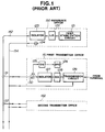
- reference numeral 250 designates a reference office, and the reference office 250 includes a temperature stabilization circuit 221 for stabilizing oscillation wavelengths of a laser diode 222, a multimode laser diode 222 for emitting light of reference wavelengths, and an isolator for interrupting light from a transmission line 252.
- Reference numeral 240 designates a receiver office, and the receiver office 240 includes a demultiplexer 224 for demultiplexing the optical signals of wavelengths, an O/E converter 225 for converting the optical signal at a predetermined wavelength from the demultiplexer 224 to an electric signal, a timing extraction circuit 226 for extracting a timing component from a received signal to reproduce the clock, and a code conversion circuit 227 for converting a coded signal from the transmitter office to an original.
- a reference numeral 228 designates a branching-combining device for branching and/or combining the optical signal.
- wavelengths ⁇ A- ⁇ D are respectively assigned to the transmitter offices 261-264, multiplexed lights of such wavelengths are transmitted through the light transmission line 252, and the receiver office 240 demultiplexes the multiplexed wavelengths into signals of respective wavelengths.
- the reference office 250 supplies lights of stable absolute wavelengths to the respective transmitter offices, and each transmitter office stabilizes its own oscillation wavelength based on the reference wavelengths of reference light, as described in Fig. 1.
- the multimode laser diode 222 is used as a reference light source for emitting reference light of absolute wavelengths, and each one wavelength thereof in its londitudinal mode is assigned to each transmitter office.
- the laser diode 222 supplies light of reference wavelengths under a condition under which the wavelengths are stabilized by the temperature stabilization circuit 221.
- the reference light output from the laser diode 222 passes through the isolator 223, is transmitted to the light transmission line 252, is branched by the b-c device 228 and enters the respective transmitter offices 261-264.
- their light sources are respectively tuned to the assigned wavelengths of the reference light. Thereafter, each transmitter office performs an optical communication at the assigned wavelength.
- optical signals of wavelengths ⁇ A- ⁇ D are respectively supplied from the transmitter offices 261, 262, 263 and 264, are combined by the b-c device 228 and are transmitted to the receiver office 240 through the transmission line 252.
- a reference clock is not used, dissimilarly to the example of Fig. 1.
- the optical signal input into the receiver office 240 is demultiplexed into signals of respective wavelengths ⁇ A- ⁇ D by the demultiplexer 224, and the signal of wavelength ⁇ A, for example, is converted to an electric signal by the O/E converter 225.
- the timing extraction circuit 226 extracts the timing component from the received signal to regenerate the clock.
- the timing extraction circuit 226 operates the code conversion circuit 227 at such a timing.
- the code conversion circuit 227 converts the coded signal transmitted from the transmitter office to its original and supplies the original to the terminal.
- the signals at wavelengths ⁇ B- ⁇ D are respectively converted to electric signals at circuits 271, 272 and 273, and thereafter the electric signals are code-converted with the extracted clock.
- the coded signals at wavelengths ⁇ A- ⁇ D are respectively received.
- WDM signal is demultiplexed into signals at respective wavelengths by the receiver office 240 to achieve optical communication.
- the transmitted code needs to be converted to such a code that has a timing component (e.g., CMI and RZ code) in the transmitter office so that the clock can be regenerated in the receiver office, and thus the size of circuits in transmitter and receiver offices increases.
- a timing component e.g., CMI and RZ code
- a wavelength-tuning and clock-synchronous system of an optical communication network which comprises a step of transmitting a reference signal, in which data of a reference wavelength and data of a reference clock are superposed, from a reference office, a step of tuning a wavelength of a signal, which is to be transmitted, based on the reference wavelength of the reference signal, in a transmitter office, and a step of synchronizing a clock, at which the signal is transmitted from the transmitter office, based on the reference clock extracted from the reference signal, in the transmitter office.
- a wavelength division multiplexing optical communication network comprises a reference office for transmitting a reference signal, in which data of a reference wavelength and data of a reference clock are superposed, and a transmitter office.
- tuning of a wavelength of a signal, which is to be transmitted from the transmitter office, based on the reference wavelength of the reference signal and synchronization of a clock, at which the signal is transmitted from the transmitter office, based on the reference clock extracted from the reference signal are performed.
- a wavelength-tuning and clock-synchronous system in an optical communication network comprises a step of transmitting a reference signal, in which data of a reference wavelength and data of a reference clock are superposed, from a reference office, a step of tuning a wavelength of a signal, which is to be transmitted, based on the reference wavelength of the reference signal, in a transmitter office, a step of synchronizing a clock, at which the signal is transmitted from the transmitter office, based on the reference clock extracted from the reference signal, in the transmitter office, a step of extracting a clock from the reference signal in a receiver office, and a step of receiving wavelength-division-multiplexed signals as time-division-demultiplexed parallel data by using the extracted clock in the receiver office.
- a wavelength division multiplexing optical communication network comprises a reference office for transmitting a reference signal, in which data of a reference wavelength and data of a reference clock are superposed, a transmitter office, and a receiver office for receiving wavelength-division-multiplexed signals as time-division-demultiplexed parallel data by using a clock extracted from the reference signal.
- tuning of a wavelength of a signal, which is to be transmitted from the transmitter office, based on the reference wavelength of the reference signal and synchronization of a clock, at which the signal is transmitted from the transmitter office, based on the reference clock extracted from the reference signal are performed.
- a wavelength-tuning and clock-synchronous system in an optical communication network comprises a step of transmitting a reference signal, in which data of a reference wavelength and data of a reference clock are superposed from a reference office.
- a wavelength division multiplexing optical communication network comprises a reference office for transmitting a reference signal, in which data of a reference wavelength and data of a reference clock are superposed.
- Fig. 1 is a block diagram showing a first prior art system.
- Fig. 2 is a block diagram showing another prior art system.
- Fig. 3 is a block diagram showing a first embodiment according to the present invention.
- Figs. 4A-4D are respectively graphs showing waveforms at portions in Fig. 3.
- Fig. 5 is a block diagram showing a second embodiment according to the present invention.
- Figs. 6A-6F are respectively graphs showing waveforms at portions in Fig. 5.
- Fig. 7 is a block diagram showing an example of a system in which the system of Fig. 3 is usable.
- Fig. 3 is a block diagram showing a first embodiment of the present invention.
- Figs. 4A-4D respectively show waveforms at portions in the structure shown in Fig. 3.
- reference numeral 100 designates a reference office
- the reference office 100 includes a sawtooth waveform generating circuit 1 for generating a sawtooth waveform current, an E/O converter 2 for converting current supplied by the sawtooth waveform generating circuit 1 to light, a light wavelength selector 3 for selecting light of a predetermined wavelength from the light supplied from the E/O converter 2, and an isolator for interrupting light from a transmission line 20 while transmitting therethrough the light from the wavelength selector 3.
- Reference numeral 51-54 respectively designate transmitter offices, each of the transmitter offices 51-54 includes an O/E converter 5 for converting lights from the E/O converter 2 in the reference office 100 and an E/O converter of the associated transmitter office to electric signals, an auto-frequency control (AFC) circuit 6 for stabilizing an output wavelength of the E/O converter 9 based on the reference wavelength supplied from the reference office 100, a clock extraction circuit 7 for extracting a clock from the signal received by the O/E converter 5, a digital transmitter circuit 8 for processing data from an associated terminal by using the clock supplied from the clock extraction circuit 7 to generate a digital signal, an E/O converter 9 for converting the electric digital signal from the digital transmitter circuit 8 to an optical signal, and an isolator 10 for interrupting light from the transmission line 20 while transmitting therethrough the optical signal from the E/O converter 9.
- AFC auto-frequency control
- the AFC circuit 6 comprises, for example, a circuit for controlling the output wavelength of the E/O converter 9 so that the amplitude of a beat signal (between the light at reference wavelength from the reference office 100 and the light from the E/O converter 9 in the associated transmitter office) from the O/E converter 5 is maintained at a constant value.
- Reference numerals 11-15 respectively designate branching-combining (b-c) devices for branching and/or combining light in both opposite directions.
- the transmitter offices 51, 53 and 54 respectively have the same structure as that of the transmitter office 52.
- the E/O converters 2 and 9 are respectively light emitting devices whose oscillation wavelengths are changeable by a change in the amount of current injected through a wavelength control terminal thereof, and distributed feedback (DFB) lasers and distributed Bragg reflection (DBR) lasers, for example, are usable as such a light emitting device.
- the wavelength selector 3 is a device for transmitting therethrough an input light whose wavelength coincides with a resonance wavelength of the selector 3, and Fabry-Perot etalon optical resonators, for example, can be used as the wavelength selector.
- PIN-photodiodes (PD) and avalanche photodiodes (APD), for example are available.
- the sawtooth waveform generating circuit 1 supplies a sawtooth waveform current of periods of 100ns (i.e., 10MHz) as shown in Fig. 4A to the wavelength control terminal of the E/O converter 2.
- the sawtooth waveform current is a varying current for causing the output wavelength of the E/O converter 2 to vary at periods corresponding to a value that is four times a resonance wavelength interval of the wavelength selector 3.
- the wavelength of the output light of the E/O converter 2 is varied at periods of 100ns (i.e., four times the resonance wavelength interval of the wavelength selector 3) by the sawtooth waveform current. If this output light enters the wavelength selector 3, the wavelength selector 3 supplies an output when the wavelength of the incident light thereon coincides with the resonance wavelength of the wavelength selector 3.
- the output of the selector 3 is composed of pulses at wavelengths ⁇ A, ⁇ B, ⁇ C and ⁇ D consecutively emitted at intervals of 25ns, as shown in Fig. 4B.
- the pulses are transmitted through the isolator 4 to be output into the light transmision line 20.
- the reference pulses shown in Fig. 4B supplied from the reference office 100 are branched by the b-c devices 12-15, and input into the respective transmitter offices 51-54.
- the reference pulses incident on the second transmitter office 52 are branched by the b-c device 11 and input into the O/E converter 5.
- the light branching towards the isolator 10 is interrupted thereby.
- the output light from the E/O converter 9 passes through the isolator 10 and is divided by the b-c device 11. One of the divided lights is transmitted to the transmission line 20, while the other one is input into the O/E converter 5.
- the wavelength ⁇ B is beforehand assigned to the second transmitter office 2, and therefore, the output light of the E/O converter 9 is initially supplied at a wavelength near the reference wavelength ⁇ B.
- the reference pulses incident on the O/E converter 5 and the signal light from the E/O converter 9 are respectively converted to electric signals by the O/E converter 5.
- a beat voltage is generated, which corresponds to a wavelength difference between the pulse light at wavelength ⁇ B of the reference light and the signal light from the E/O converter 9, and thus beat pulses as shown in Fig. 4C are obtained.
- the beat pulses are input into the AFC circuit 6.
- the amplitude of the beat signal increases as the wavelength difference between the reference light and the light, from the E/O converter 9 decreases, while the amplitude lessens as the wavelength difference enlarges. Therefore, the AFC circuit 6 controls the wavelength of the output of the E/O converter 9 so that the amplitude of the beat signal is made constant, for example, by detecting the amplitude of the beat signal.
- the control signal can be supplied through the wavelength control terminal of the E/O converter 9 as a control current.
- the second transmitter office 52 can stably output a signal at the wavelength ⁇ B based on the reference light from the reference office 100 shown in Fig. 4B.
- the first, third and fourth transmitter offices 51, 53 and 54 can tune their signal lights to wavelengths ⁇ A, ⁇ C and ⁇ D based on the reference light supplied from the reference office 100.
- the clock extraction circuit 7 extracts only a signal component supplied from the reference office 100 as shown in Fig. 4B, from among the signal from the reference office 100, the signal from the associated office and signals from the other offices, and regenerates a clock which has a certain logic amplitude. Since the pulse signal from the reference office 100 contains a clock component of 40MHz, the clock can be readily regenerated by separating or filtering the reference signal by using a filter of 40MHz or the like (see Fig. 4D). The signal from the terminal is processed in the digital transmitter circuit 8 by using the clock shown in Fig.
- the processed digital signal is converted to an optical signal by the E/O converter 9 to be transmitted to the transmission line 20.
- the clock-synchronization is achieved in the second transmitter office 52 based on the reference light as shown in Fig. 4B from the reference office 100.
- the clock-synchronization is achieved based on the reference light from the common reference office 100 also in the respective transmitter offices 51, 53 and 54.
- the clock-synchronization is performed in all the transmitter offices.
- the clock frequency is set to 40MHz and four wavelengths are used in the system of this embodiment, figures are not limited thereto.
- the period of a sawtooth waveform in the reference office 100 may be set to a necessary period.
- the amount of current in a sawtooth waveform may be set to a desired value.
- Fig. 5 is a block diagram of a second embodiment of the present invention.
- Figs. 6A-6F are respectively graphs showing waveforms at portions of the second embodiment shown in Fig. 5.
- a reference office 100 is the same as that of Fig. 3.
- Tranmsitter offices 61-64 are also substantially the same as those of Fig. 3.
- a receiver office 110 includes an O/E converter 35 for converting an optical signal from a transmission line 70 to an electric signal, a clock extraction circuit 36 for extracting a clock component supplied by the reference office 100 from the electric signal from the O/E converter 35, a tunable filter 37 for transmitting only a signal at a predetermined wavelength of the optical signal from the transmission line 70 under the control of the clock extraction circuit 36, an O/E converter 38 for converting the optical signal transmitted through the tunable optical filter 37 to an electric signal, and a time-division demultiplexing (DMUX) circuit 39 for time-division demultiplexing the signal from the O/E converter 38.
- Reference numerals 40 and 41 designate branching-combining (b-c) devices for branching and/or combining the optical signal.
- the optical filter 37 is a filter whose wavelength of the transmitted light is changeable by controlling the amount of current injected through its wavelength control terminal, and, for example, a DFB laser structure can be utilized as the optical filter 37.
- the time-division demultiplexing of the optical signal supplied from the transmitter offices 61-64 will be described with reference to Fig. 5.
- oscillation wavelengths of the transmitter offices 61-64 are respectively set to wavelengths ⁇ A- ⁇ D based on the reference signal from the reference office 100, and the clock frequency is synchronized with 10MHz by frequency-demultiplying the regenerated clock of 40MHz.
- the receiver office 110 time-division demultiplexes optical signals at wavelengths ⁇ A- ⁇ D base on the reference signal from the reference office 100.
- the operation of the transmitter offices 61-64 will be described.
- the reference light output from the reference office 100 are input into the transmitter offices 61-64 and the receiver office 110 through the b-c device 41.
- the transmitter offices 61-64 respectively stabilize oscillation wavelengths of transmitting light sources at previously assigned wavelengths based on the reference light.
- the clock of 10MHz is extracted (see Fig. 6C), and the transmitted data is created by using this clock.
- the wavelengths and clocks of the transmitter offices 61-64 are synchronized to those of the reference office 100. This is substantially the same as the first embodiment (see Figs. 6A-6C).
- the output signals of the reference office 100 and the transmitter offices 61-64 are input into the receiver office 110, and are branched by the b-c device 40.
- One of the divided signals is input into the O/E converter 35, while the other one is input into the optical filter 37.
- the O/E converter 35 converts the optical signal to an electric signal, and supplies the electric signal to the clock extraction circuit 36.
- the clock extraction circuit 36 extracts a clock component of 40MHz supplied from the reference office 100 from the electric signal from the O/E converter 35, and regenerates pulses of a constant logic amplitude (see Fig. 6D).
- currents corresponding to wavelengths ⁇ A- ⁇ D of current-wavelength characteristics of the optical filter 37 are generated at the clock period as shown in Fig. 6E, and the current is supplied to the wavelength control terminal of the optical filter 37.
- the optical filter 37 changes the transmission wavelength at intervals of 25ns from ⁇ A to ⁇ D through ⁇ B, ⁇ C under the control of its control current, as shown in Fig. 6F, and therefore, the signals of wavelengths ⁇ A- ⁇ D are time-division demultiplexed by the optical filter 37 and output therefrom.
- the output from the optical filter 37 is input into the O/E converter 38 and converted to an electric signal thereby.
- the electric signal is input into the DMUX circuit 39.
- the DMUX circuit 39 converts serial data from the O/E converter 38 (see Fig. 6F) to parallel data by using the clock from the clock extraction circuit 36 (see Fig. 6D), and separates the data.
- data from the transmitter offices 61-64 can be time-division demultiplexed by using the reference signal from the reference office 100.
- the data speed is set to 10Mb/s and demultiplexing of signals at four wavelengths are used in the system of this embodiment, figures are not limited thereto.
- the period of a sawtooth waveform in the reference office 100 may be set to a necessary period.
- the amount of current in a sawtooth waveform may be set to a desired value.
- the wavelength-tuning and clock-synchronization systems as described with reference to Figs. 3 and 4A-4D can be employed in a tuning-synchronization system of a transmitter unit in an end office which-comprises a transmitter portion 81 and a receiver portion 91 as shown in Fig. 7.
- receiving can be achieved in a time-division demultiplexing system using the system described in Figs. 5 and 6A-6F.
- wavelength information and clock information are superposed in a reference signal supplied from a reference office, and hence wavelength-tuning and clock-synchronization can be executed, for example, by connecting the reference office and the transmitter office with a single transmission line. As a result, cost of the transmission line can be reduced.
- a clock component is contained in a reference light supplied from a reference office, so that a clock can be extracted without coding a transmitted data signal. Furthermore, if WDM signals at a plurality of wavelengths are time-division demultiplexed in a receiver office, only one optical receiver will suffice. Thus, circuits in the transmitter and receiver offices can be greatly reduced.
- a reference office transmits a reference signal via a single transmission line. Data of a reference wavelength and data of a reference clock are superposed in the reference signal.
- a transmitter office supplies an optical signal whose wavelength is tuned based on the reference wavelength extracted from the reference signal and whose clock is synchronized based on the reference clock extracted from the reference signal.
- a receiver office receives wavelength-division-multiplexed signals as time-division-demultiplexed parallel data by using a clock extracted from the reference signal.
Abstract
Description
- The present invention relates to a wavelength-tuning and clock-synchronous system used in a wavelength division multiplexing (WDM) system or network, a WDM optical communication system in which wavelength and clock of a signal transmitted from a transmitter office are respectively tuned and synchronized based on a reference signal transmitted from a reference office, a WDM optical communication system in which a receiver office time-division demultiplexes wavelength division multiplexed signals of plural wavelengths based on a reference signal transmitted from a reference office, a WDM optical communication system in which these techniques are appropriately combined and the like.
- In wavelength division multiplexing (WDM) optical communication systems, different wavelengths are individually assigned to a plurality of transmitter offices or stations, and it is necessary to tune these wavelengths to oscillation wavelengths of reference light source respectively and at the same time to synchronize clocks of the transmitter offices, which determine a transmission speed of the system, with each other.
- A prior art wavelength-tuning and clock-synchronous system in such a WDM optical communication system will be described with reference to Fig. 1. In Fig. 1,
reference numeral 150 designates a reference office, and thereference office 150 involves atemperature stabilization circuit 121 for stabilizing the oscillation wavelength of a laser diode (LD) 122, amultimode laser diode 122 for supplying light of reference or absolute wavelengths, an isolator for interrupting light from a transmission line oroptical fiber 152 and a circuit for generating a reference clock.Reference numerals 161 and 162 respectively designate first and second transmitter offices, and each of thetransmitter offices 161 and 162 includes an O/E converter 125 for converting an input signal light to an electric signal, an auto-frequency control (AFC)circuit 126 for stabilizing the wavelength of an output light of an E/O converter 128 based on the electric signal from the O/E converter 125, anisolator 127 for interrupting light from thetransmission line 152, an E/O converter for converting an electric signal from atransmission circuit 129 to an optical signal while the wavelength of the optical signal being controlled by theAFC circuit 126, atransmission circuit 129 for processing a signal from a terminal with synchronized with the clock from a transmission line orcoaxial cable 154 to generate a digital signal, and a branching-combining (b-c)device 130 for branching and/or combining the optical signal.Reference numerals optical fiber 152. As described above, thetransmission line 152 is, for example, an optical fiber, and thetransmission line 154 is, for example, a coaxial cable. - Initially, the wavelength-tuning will be described. The
reference office 150 supplies light of absolute wavelengths to therespective transmitter offices 161, 162, ···, and the respective transmitter offices conduct tuning to assigned wavelengths. Thus, the wavelength tuning is achieved in each transmitter office. Themultimode laser diode 122 is used as a reference light source for emitting light of absolute wavelengths, and each one of wavelengths in its longitudinal mode is assigned to each transmitter office. Since the oscillation wavelength of themultimode laser diode 122 is changeable depending on a change in temperature, the oscillation wavelength needs to be stabilized by thetemperature stabilization circuit 121. Thus, the light of reference wavelengths is supplied to each transmitter office. The light of reference wavelengths output by themultimode laser diode 122 is transmitted to the opticalfiber transmission line 152 via theisolator 123, and is branched by therespective b-c devices respective transmitter offices 161, 162, ···. The light of reference wavelengths input into the transmitter office is further branched by theb-c device 130 to be input into the O/E converter 125. At the same time, the output light of the E/O converter 128 is supplied through theisolator 127 and is branched by theb-c device 130. One of the divided lights is transmitted to thelight transmission line 152, while the other one is input into the O/E converter 125. - At this time, the wavelength of the output light from the E/
O converter 128 is previously set to a value that is in the vicinity of the wavelength assigned to the associated terminal. Further, the reference light incident on the O/E converter 125 and the signal light from the E/O converter 128 are converted to electric signals by the O/E converter 125. Therefore, a beat voltage, which corresponds to a wavelength difference between the reference light and the signal light from the E/O converter 128, is generated. TheAFC circuit 126 controls the E/O converter 128 so that the amplitude of the beat signal is maintained at a constant value. That control signal is supplied to the E/O converter 128 as a control current, through a wavelength control terminal of the E/O converter 128. In the above manner, each transmitter office performs the wavelength tuning based on the light of reference wavelengths supplied from thereference office 150. - Turning to the clock synchronization, a stable
clock generating circuit 124 is disposed in thereference office 150, and a reference clock is supplied to therespective transmitter offices 161, 162, ··· through thecoaxial cable 154. The clock input into the transmitter office is supplied to thetransmission circuit 129, and a signal from the terminal is processed thereby to generate the digital signal in thetransmission circuit 129. The digital signal is then converted to the optical signal by the E/O converter 128 to be transmitted to thetransmission line 152. Thus, all thetransmitter offices 161, 162, ··· are synchronized with thereference office 150. - Another prior art WDM optical communication system will be described with reference to Fig. 2. In Fig. 2,
reference numeral 250 designates a reference office, and thereference office 250 includes atemperature stabilization circuit 221 for stabilizing oscillation wavelengths of alaser diode 222, amultimode laser diode 222 for emitting light of reference wavelengths, and an isolator for interrupting light from atransmission line 252.Reference numeral 240 designates a receiver office, and thereceiver office 240 includes a demultiplexer 224 for demultiplexing the optical signals of wavelengths, an O/E converter 225 for converting the optical signal at a predetermined wavelength from the demultiplexer 224 to an electric signal, atiming extraction circuit 226 for extracting a timing component from a received signal to reproduce the clock, and acode conversion circuit 227 for converting a coded signal from the transmitter office to an original. Areference numeral 228 designates a branching-combining device for branching and/or combining the optical signal. - In th system of Fig. 2, wavelengths λA-λD are respectively assigned to the transmitter offices 261-264, multiplexed lights of such wavelengths are transmitted through the
light transmission line 252, and thereceiver office 240 demultiplexes the multiplexed wavelengths into signals of respective wavelengths. Thereference office 250 supplies lights of stable absolute wavelengths to the respective transmitter offices, and each transmitter office stabilizes its own oscillation wavelength based on the reference wavelengths of reference light, as described in Fig. 1. Themultimode laser diode 222 is used as a reference light source for emitting reference light of absolute wavelengths, and each one wavelength thereof in its londitudinal mode is assigned to each transmitter office. Since the oscillation wavelength of themultimode laser diode 222 varies depending on a change in temperature, thelaser diode 222 supplies light of reference wavelengths under a condition under which the wavelengths are stabilized by thetemperature stabilization circuit 221. The reference light output from thelaser diode 222 passes through theisolator 223, is transmitted to thelight transmission line 252, is branched by theb-c device 228 and enters the respective transmitter offices 261-264. In the respective transmitter offices, their light sources are respectively tuned to the assigned wavelengths of the reference light. Thereafter, each transmitter office performs an optical communication at the assigned wavelength. Thus, optical signals of wavelengths λA-λD are respectively supplied from thetransmitter offices b-c device 228 and are transmitted to thereceiver office 240 through thetransmission line 252. In this example, a reference clock is not used, dissimilarly to the example of Fig. 1. - The optical signal input into the
receiver office 240 is demultiplexed into signals of respective wavelengths λA-λD by the demultiplexer 224, and the signal of wavelength λA, for example, is converted to an electric signal by the O/E converter 225. Thetiming extraction circuit 226 extracts the timing component from the received signal to regenerate the clock. Thetiming extraction circuit 226 operates thecode conversion circuit 227 at such a timing. Thecode conversion circuit 227 converts the coded signal transmitted from the transmitter office to its original and supplies the original to the terminal. Similarly, the signals at wavelengths λB-λD are respectively converted to electric signals atcircuits receiver office 240 to achieve optical communication. - In the prior art example of Fig. 1, however, the light of reference wavelengths for wavelength-tuning and the reference clock for clock-synchronization are respectively transmitted via separate transmission lines from the reference office to the transmitter offices, in WDM communications. As a result, cost for transmission lines increases.
- Further, in the prior art example shown in Fig. 2, optical receivers need to be used for respective wavelengths of the WDM communication, the transmitted code needs to be converted to such a code that has a timing component (e.g., CMI and RZ code) in the transmitter office so that the clock can be regenerated in the receiver office, and thus the size of circuits in transmitter and receiver offices increases.
- It is a first object of the present invention to provide a wavelength-tuning and clock-synchronous system of an optical communication network in which a reference office supplies a reference signal via a single transmission line, and a wavelength division multiplexing optical communication network using such a system.
- It is a second object of the present invention to provide a wavelength-tuning and clock-synchronous system of an optical communication network in which a reference office supplies a reference signal via a single transmission line and a transmitter office performs wavelength-tuning and clock-synchronization based on the reference signal from the reference office, and a wavelength division multiplexing optical communication network using such a system.
- It is a third object of the present invention to provide a wavelength-tuning and clock-synchronous system of an optical communication network in which wavelength division multiplexed signals are demultiplexed and received by a single receiver, and a wavelength-tuning and clock-synchronous system in which a clock can be regenerated without coding a transmitted signal.
- According to one aspect of the invention, a wavelength-tuning and clock-synchronous system of an optical communication network which comprises a step of transmitting a reference signal, in which data of a reference wavelength and data of a reference clock are superposed, from a reference office, a step of tuning a wavelength of a signal, which is to be transmitted, based on the reference wavelength of the reference signal, in a transmitter office, and a step of synchronizing a clock, at which the signal is transmitted from the transmitter office, based on the reference clock extracted from the reference signal, in the transmitter office.
- According to another aspect of the invention, a wavelength division multiplexing optical communication network comprises a reference office for transmitting a reference signal, in which data of a reference wavelength and data of a reference clock are superposed, and a transmitter office. In the transmitter office, tuning of a wavelength of a signal, which is to be transmitted from the transmitter office, based on the reference wavelength of the reference signal and synchronization of a clock, at which the signal is transmitted from the transmitter office, based on the reference clock extracted from the reference signal are performed.
- According to another aspect of the invention, a wavelength-tuning and clock-synchronous system in an optical communication network comprises a step of transmitting a reference signal, in which data of a reference wavelength and data of a reference clock are superposed, from a reference office, a step of tuning a wavelength of a signal, which is to be transmitted, based on the reference wavelength of the reference signal, in a transmitter office, a step of synchronizing a clock, at which the signal is transmitted from the transmitter office, based on the reference clock extracted from the reference signal, in the transmitter office, a step of extracting a clock from the reference signal in a receiver office, and a step of receiving wavelength-division-multiplexed signals as time-division-demultiplexed parallel data by using the extracted clock in the receiver office.
- According to another aspect of the invention, a wavelength division multiplexing optical communication network comprises a reference office for transmitting a reference signal, in which data of a reference wavelength and data of a reference clock are superposed, a transmitter office, and a receiver office for receiving wavelength-division-multiplexed signals as time-division-demultiplexed parallel data by using a clock extracted from the reference signal. In the transmitter office, tuning of a wavelength of a signal, which is to be transmitted from the transmitter office, based on the reference wavelength of the reference signal and synchronization of a clock, at which the signal is transmitted from the transmitter office, based on the reference clock extracted from the reference signal are performed.
- According to another aspect of the invention, a wavelength-tuning and clock-synchronous system in an optical communication network comprises a step of transmitting a reference signal, in which data of a reference wavelength and data of a reference clock are superposed from a reference office.
- According to another aspect of the invention, a wavelength division multiplexing optical communication network comprises a reference office for transmitting a reference signal, in which data of a reference wavelength and data of a reference clock are superposed.
- These advantages and others will be more readily understood in connection with the following detailed description of the preferred embodiments in conjunction with the drawings.
- Fig. 1 is a block diagram showing a first prior art system.
- Fig. 2 is a block diagram showing another prior art system.
- Fig. 3 is a block diagram showing a first embodiment according to the present invention.
- Figs. 4A-4D are respectively graphs showing waveforms at portions in Fig. 3.
- Fig. 5 is a block diagram showing a second embodiment according to the present invention.
- Figs. 6A-6F are respectively graphs showing waveforms at portions in Fig. 5.
- Fig. 7 is a block diagram showing an example of a system in which the system of Fig. 3 is usable.
- Fig. 3 is a block diagram showing a first embodiment of the present invention. Figs. 4A-4D respectively show waveforms at portions in the structure shown in Fig. 3.
- In Fig. 3,
reference numeral 100 designates a reference office, and thereference office 100 includes a sawtooth waveform generating circuit 1 for generating a sawtooth waveform current, an E/O converter 2 for converting current supplied by the sawtooth waveform generating circuit 1 to light, alight wavelength selector 3 for selecting light of a predetermined wavelength from the light supplied from the E/O converter 2, and an isolator for interrupting light from atransmission line 20 while transmitting therethrough the light from thewavelength selector 3. Reference numeral 51-54 respectively designate transmitter offices, each of the transmitter offices 51-54 includes an O/E converter 5 for converting lights from the E/O converter 2 in thereference office 100 and an E/O converter of the associated transmitter office to electric signals, an auto-frequency control (AFC)circuit 6 for stabilizing an output wavelength of the E/O converter 9 based on the reference wavelength supplied from thereference office 100, a clock extraction circuit 7 for extracting a clock from the signal received by the O/E converter 5, adigital transmitter circuit 8 for processing data from an associated terminal by using the clock supplied from the clock extraction circuit 7 to generate a digital signal, an E/O converter 9 for converting the electric digital signal from thedigital transmitter circuit 8 to an optical signal, and anisolator 10 for interrupting light from thetransmission line 20 while transmitting therethrough the optical signal from the E/O converter 9. TheAFC circuit 6 comprises, for example, a circuit for controlling the output wavelength of the E/O converter 9 so that the amplitude of a beat signal (between the light at reference wavelength from thereference office 100 and the light from the E/O converter 9 in the associated transmitter office) from the O/E converter 5 is maintained at a constant value. - Reference numerals 11-15 respectively designate branching-combining (b-c) devices for branching and/or combining light in both opposite directions. The
transmitter offices transmitter office 52. - The E/
O converters 2 and 9 are respectively light emitting devices whose oscillation wavelengths are changeable by a change in the amount of current injected through a wavelength control terminal thereof, and distributed feedback (DFB) lasers and distributed Bragg reflection (DBR) lasers, for example, are usable as such a light emitting device. Thewavelength selector 3 is a device for transmitting therethrough an input light whose wavelength coincides with a resonance wavelength of theselector 3, and Fabry-Perot etalon optical resonators, for example, can be used as the wavelength selector. As the O/E converter 5, PIN-photodiodes (PD) and avalanche photodiodes (APD), for example, are available. - The wavelength-tuning and clock synchronization will be described with reference to Fig. 3. In this embodiment, it is assumed that wavelengths λA-λD are respectively assigned to the first to fourth transmitter offices 51-54 and that the system clock frequency is 40MHz. In the
reference office 100, the sawtooth waveform generating circuit 1 supplies a sawtooth waveform current of periods of 100ns (i.e., 10MHz) as shown in Fig. 4A to the wavelength control terminal of the E/O converter 2. The sawtooth waveform current is a varying current for causing the output wavelength of the E/O converter 2 to vary at periods corresponding to a value that is four times a resonance wavelength interval of thewavelength selector 3. - The wavelength of the output light of the E/
O converter 2 is varied at periods of 100ns (i.e., four times the resonance wavelength interval of the wavelength selector 3) by the sawtooth waveform current. If this output light enters thewavelength selector 3, thewavelength selector 3 supplies an output when the wavelength of the incident light thereon coincides with the resonance wavelength of thewavelength selector 3. The output of theselector 3 is composed of pulses at wavelengths λA, λB, λC and λD consecutively emitted at intervals of 25ns, as shown in Fig. 4B. The pulses are transmitted through theisolator 4 to be output into thelight transmision line 20. - Next, the wavelength-tuning and clock-synchronization, which are effected in the transmitter offices 51-54 based on the pulses from the
reference office 100, will be described. The reference pulses shown in Fig. 4B supplied from thereference office 100 are branched by the b-c devices 12-15, and input into the respective transmitter offices 51-54. The reference pulses incident on thesecond transmitter office 52 are branched by the b-c device 11 and input into the O/E converter 5. The light branching towards theisolator 10 is interrupted thereby. At the same time, the output light from the E/O converter 9 passes through theisolator 10 and is divided by the b-c device 11. One of the divided lights is transmitted to thetransmission line 20, while the other one is input into the O/E converter 5. Here, the wavelength λB is beforehand assigned to thesecond transmitter office 2, and therefore, the output light of the E/O converter 9 is initially supplied at a wavelength near the reference wavelength λB. - The reference pulses incident on the O/
E converter 5 and the signal light from the E/O converter 9 are respectively converted to electric signals by the O/E converter 5. At this time, a beat voltage is generated, which corresponds to a wavelength difference between the pulse light at wavelength λB of the reference light and the signal light from the E/O converter 9, and thus beat pulses as shown in Fig. 4C are obtained. The beat pulses are input into theAFC circuit 6. - The amplitude of the beat signal increases as the wavelength difference between the reference light and the light, from the E/O converter 9 decreases, while the amplitude lessens as the wavelength difference enlarges. Therefore, the
AFC circuit 6 controls the wavelength of the output of the E/O converter 9 so that the amplitude of the beat signal is made constant, for example, by detecting the amplitude of the beat signal. The control signal can be supplied through the wavelength control terminal of the E/O converter 9 as a control current. Thus, thesecond transmitter office 52 can stably output a signal at the wavelength λB based on the reference light from thereference office 100 shown in Fig. 4B. Similarly, the first, third andfourth transmitter offices reference office 100. - Next, the clock-synchronization will be described. Part of the signal converted to an electric signal by the O/
E converter 5 is input into the clock extraction circuit 7. The clock extraction circuit 7 extracts only a signal component supplied from thereference office 100 as shown in Fig. 4B, from among the signal from thereference office 100, the signal from the associated office and signals from the other offices, and regenerates a clock which has a certain logic amplitude. Since the pulse signal from thereference office 100 contains a clock component of 40MHz, the clock can be readily regenerated by separating or filtering the reference signal by using a filter of 40MHz or the like (see Fig. 4D). The signal from the terminal is processed in thedigital transmitter circuit 8 by using the clock shown in Fig. 4D, and the processed digital signal is converted to an optical signal by the E/O converter 9 to be transmitted to thetransmission line 20. Thus, the clock-synchronization is achieved in thesecond transmitter office 52 based on the reference light as shown in Fig. 4B from thereference office 100. Similarly, the clock-synchronization is achieved based on the reference light from thecommon reference office 100 also in therespective transmitter offices - Although the clock frequency is set to 40MHz and four wavelengths are used in the system of this embodiment, figures are not limited thereto. When a change in the clock frequency is desired, the period of a sawtooth waveform in the
reference office 100 may be set to a necessary period. Further, when a change in the number of wavelengths is desired, the amount of current in a sawtooth waveform may be set to a desired value. - Fig. 5 is a block diagram of a second embodiment of the present invention. Figs. 6A-6F are respectively graphs showing waveforms at portions of the second embodiment shown in Fig. 5.
- In Fig. 5, a
reference office 100 is the same as that of Fig. 3. Tranmsitter offices 61-64 are also substantially the same as those of Fig. 3. In Fig. 5, a receiver office 110 includes an O/E converter 35 for converting an optical signal from atransmission line 70 to an electric signal, aclock extraction circuit 36 for extracting a clock component supplied by thereference office 100 from the electric signal from the O/E converter 35, atunable filter 37 for transmitting only a signal at a predetermined wavelength of the optical signal from thetransmission line 70 under the control of theclock extraction circuit 36, an O/E converter 38 for converting the optical signal transmitted through the tunableoptical filter 37 to an electric signal, and a time-division demultiplexing (DMUX)circuit 39 for time-division demultiplexing the signal from the O/E converter 38.Reference numerals - As the O/
E converters optical filter 37 is a filter whose wavelength of the transmitted light is changeable by controlling the amount of current injected through its wavelength control terminal, and, for example, a DFB laser structure can be utilized as theoptical filter 37. - The time-division demultiplexing of the optical signal supplied from the transmitter offices 61-64 will be described with reference to Fig. 5. In this embodiment, as described in Fig. 5, oscillation wavelengths of the transmitter offices 61-64 are respectively set to wavelengths λA-λD based on the reference signal from the
reference office 100, and the clock frequency is synchronized with 10MHz by frequency-demultiplying the regenerated clock of 40MHz. The receiver office 110 time-division demultiplexes optical signals at wavelengths λA-λD base on the reference signal from thereference office 100. - The operation of the transmitter offices 61-64 will be described. The reference light output from the
reference office 100 are input into the transmitter offices 61-64 and the receiver office 110 through theb-c device 41. The transmitter offices 61-64 respectively stabilize oscillation wavelengths of transmitting light sources at previously assigned wavelengths based on the reference light. At the same time, the clock of 10MHz is extracted (see Fig. 6C), and the transmitted data is created by using this clock. Thus, the wavelengths and clocks of the transmitter offices 61-64 are synchronized to those of thereference office 100. This is substantially the same as the first embodiment (see Figs. 6A-6C). - Next, the manner, in which optical signals of wavelengths supplied from the transmitter offices synchronized with the
reference office 100 are time-division demultiplexed, will be described. The output signals of thereference office 100 and the transmitter offices 61-64 are input into the receiver office 110, and are branched by theb-c device 40. One of the divided signals is input into the O/E converter 35, while the other one is input into theoptical filter 37. The O/E converter 35 converts the optical signal to an electric signal, and supplies the electric signal to theclock extraction circuit 36. Theclock extraction circuit 36 extracts a clock component of 40MHz supplied from thereference office 100 from the electric signal from the O/E converter 35, and regenerates pulses of a constant logic amplitude (see Fig. 6D). Further, currents corresponding to wavelengths λA-λD of current-wavelength characteristics of theoptical filter 37 are generated at the clock period as shown in Fig. 6E, and the current is supplied to the wavelength control terminal of theoptical filter 37. Theoptical filter 37 changes the transmission wavelength at intervals of 25ns from λA to λD through λB, λC under the control of its control current, as shown in Fig. 6F, and therefore, the signals of wavelengths λA-λD are time-division demultiplexed by theoptical filter 37 and output therefrom. The output from theoptical filter 37 is input into the O/E converter 38 and converted to an electric signal thereby. The electric signal is input into theDMUX circuit 39. TheDMUX circuit 39 converts serial data from the O/E converter 38 (see Fig. 6F) to parallel data by using the clock from the clock extraction circuit 36 (see Fig. 6D), and separates the data. Thus, data from the transmitter offices 61-64 can be time-division demultiplexed by using the reference signal from thereference office 100. - Although the data speed is set to 10Mb/s and demultiplexing of signals at four wavelengths are used in the system of this embodiment, figures are not limited thereto. When a change in the data speed is desired, the period of a sawtooth waveform in the
reference office 100 may be set to a necessary period. Further, when a change in the number of wavelengths is desired, the amount of current in a sawtooth waveform may be set to a desired value. - The wavelength-tuning and clock-synchronization systems as described with reference to Figs. 3 and 4A-4D can be employed in a tuning-synchronization system of a transmitter unit in an end office which-comprises a
transmitter portion 81 and areceiver portion 91 as shown in Fig. 7. - Further, in bus type optical communication networks and star type optical communication networks, receiving can be achieved in a time-division demultiplexing system using the system described in Figs. 5 and 6A-6F.
- As described in the foregoing, according to the present invention, wavelength information and clock information are superposed in a reference signal supplied from a reference office, and hence wavelength-tuning and clock-synchronization can be executed, for example, by connecting the reference office and the transmitter office with a single transmission line. As a result, cost of the transmission line can be reduced.
- Further, according to the present invention, a clock component is contained in a reference light supplied from a reference office, so that a clock can be extracted without coding a transmitted data signal. Furthermore, if WDM signals at a plurality of wavelengths are time-division demultiplexed in a receiver office, only one optical receiver will suffice. Thus, circuits in the transmitter and receiver offices can be greatly reduced.
- Except as otherwise disclosed herein, the various components shown in outline or in block form in the figure are individually well-known in their internal construction and operation and are not critical either to the making or using of this invention or to a description of the best mode of the invention.
- While the present invention has been described with respect to what is presently considered to be the preferred embodiments, it is to be understood that the invention is not limited to the disclosed embodiments. The present invention is intended to cover various modifications and equivalent arrangements included within the sprit and scope of the appended claims.
- In a wavelength-tuning and clock-synchronous system in an optical communication network, a reference office transmits a reference signal via a single transmission line. Data of a reference wavelength and data of a reference clock are superposed in the reference signal. A transmitter office supplies an optical signal whose wavelength is tuned based on the reference wavelength extracted from the reference signal and whose clock is synchronized based on the reference clock extracted from the reference signal. A receiver office receives wavelength-division-multiplexed signals as time-division-demultiplexed parallel data by using a clock extracted from the reference signal.
Claims (22)
- A wavelength-tuning and clock-synchronous system in an optical communication network, said system comprising the steps:
transmitting a reference signal, in which data of a reference wavelength and data of a reference clock are superposed, from a reference office;
tuning a wavelength of a signal, which is to be transmitted, based on the reference wavelength of the reference signal, in a transmitter office; and
synchronizing a clock, at which the signal is transmitted from the transmitter office, based on the reference clock extracted from the reference signal, in the transmitter office. - A wavelength-tuning and clock-synchronous system according to claim 1, wherein the reference office transmits the reference signal by using current modulating means for modulating current at fixed periods each of which is the number of multiplexed wavelengths in the optical communication network times a system clock period, wavelength modulating means for modulating a wavelength of light based on the modulated current from the current modulating means and outputting light of the modulated wavelength, and a light wavelength selector which has a plurality of transmission wavelengths disposed at constant intervals and receives the light of the modulated wavelength from the wavelength modulating means to transmit therethrough only light of the transmission wavelengths.
- A wavelength-tuning and clock-synchronous system according to claim 1, wherein the transmitter office synchronizes the clock of the signal to be transmitted, by using extracting means for extracting the reference clock from the reference signal.
- A wavelength-tuning and clock-synchronous system according to claim 1, wherein the transmitter office tunes the wavelength of the signal to be transmitted, by using means for detecting a difference between the reference wavelength of the reference signal and the wavelength of the signal to be transmitted and maintaining the wavelength difference at a constant value.
- A wavelength division multiplexing optical communication network, said network comprising:
a reference office for transmitting a reference signal, in which data of a reference wavelength and data of a reference clock are superposed; and
a transmitter office, tuning of a wavelength of a signal, which is to be transmitted from said transmitter office, based on the reference wavelength of the reference signal and synchronization of a clock, at which the signal is transmitted from said transmitter office, based on the reference clock extracted from the reference signal are performed in said transmitter office. - A wavelength division multiplexing optical communication network according to claim 5, wherein said reference office comprises current modulating means for modulating current at fixed periods each of which is the number of multiplexed wavelengths in said optical communication network times a system clock period, wavelength modulating means for modulating a wavelength of light based on the modulated current from said current modulating means and outputting light of the modulated wavelength, and a light wavelength selector which has a plurality of transmission wavelengths disposed at constant intervals and receives the light of the modulated wavelength from said wavelength modulating means to transmit therethrough only light of the transmission wavelengths, and the light of the transmission wavelengths is the reference signal.
- A wavelength division multiplexing optical communication network according to claim 5, wherein said transmitter office comprises extracting means for extracting the reference clock from the reference signal to synchronize the clock of the signal to be transmitted.
- A wavelength division multiplexing optical communication network according to claim 5, wherein said transmitter office comprises means for detecting a difference between the reference wavelength of the reference signal and the wavelength of the signal to be transmitted and maintaining the wavelength difference at a constant value to tune the wavelength of the signal to be transmitted.
- A wavelength division multiplexing optical communication network according to claim 5, further comprising a single transmission line for connecting said reference office and said transmitter office.
- A wavelength-tuning and clock-synchronous system in an optical communication network, said system comprising the steps:
transmitting a reference signal, in which data of a reference wavelength and data of a reference clock are superposed, from a reference office;
tuning a wavelength of a signal, which is to be transmitted, based on the reference wavelength of the reference signal, in a transmitter office;
synchronizing a clock, at which the signal is transmitted from the transmitter office, based on the reference clock extracted from the reference signal, in the transmitter office;
extracting a clock from the reference signal in a receiver office; and
receiving wavelength-division-multiplexed signals as time-division-demultiplexed parallel data by using the extracted clock in the receiver office. - A wavelength-tuning and clock-synchronous system according to claim 10, wherein the reference office transmits the reference signal by using current modulating means for modulating current at fixed periods each of which is the number of multiplexed wavelengths in the optical communication network times a system clock period, wavelength modulating means for modulating a wavelength of light based on the modulated current from the current modulating means and outputting light of the modulated wavelength, and a light wavelength selector which has a plurality of transmission wavelengths disposed at constant intervals and receives the light of the modulated wavelength from the wavelength modulating means to transmit therethrough only light of the transmission wavelengths.
- A wavelength-tuning and clock-synchronous system according to claim 10, wherein the transmitter office synchronizes the clock of the signal to be transmitted, by using extracting means for extracting the reference clock from the reference signal.
- A wavelength-tuning and clock-synchronous system according to claim 10, wherein the transmitter office tunes the wavelength of the signal to be transmitted, by using means for detecting a difference between the reference wavelength of the reference signal and the wavelength of the signal to be transmitted and maintaining the wavelength difference at a constant value.
- A wavelength-tuning and clock-synchronous system according to claim 10, wherein the receiver office receives the wavelength-division-multiplexed signals as time-division-demultiplexed parallel data by using extracting means for extracting the clock from the reference signal, an optical filter whose transmission wavelength is controlled at a timing of the clock extracted by the extracting means, converting means for converting the wavelength-division-multiplexed signals from the optical filter to serial data of electric signals, and time-division-demultiplexing means for converting the serial data of electric signals from the converting means to the time-division-demultiplexed parallel data.
- A wavelength division multiplexing optical communication network, said network comprising:
a reference office for transmitting a reference signal, in which data of a reference wavelength and data of a reference clock are superposed;
a transmitter office, tuning of a wavelength of a signal, which is to be transmitted from said transmitter office, based on the reference wavelength of the reference signal and synchronization of a clock, at which the signal is transmitted from said transmitter office, based on the reference clock extracted from the reference signal being performed in said transmitter office; and
a receiver office for receiving wavelength-division-multiplexed signals as time-division-demultiplexed parallel data by using a clock extracted from the reference signal. - A wavelength division multiplexing optical communication network according to claim 15, wherein said reference office comprises current modulating means for modulating current at fixed periods each of which is the number of multiplexed wavelengths in said optical communication network times a system clock period, wavelength modulating means for modulating a wavelength of light based on the modulated current from said current modulating means and outputting light of the modulated wavelength, and a light wavelength selector which has a plurality of transmission wavelengths disposed at constant intervals and receives the light of the modulated wavelength from said wavelength modulating means to transmit therethrough only light of the transmission wavelengths, and the light of the transmission wavelengths is the reference signal.
- A wavelength division multiplexing optical communication network according to claim 15, wherein said transmitter office comprises extracting means for extracting the reference clock from the reference signal to synchronize the clock of the signal to be transmitted based on the reference clock.
- A wavelength division multiplexing optical communication network according to claim 15, wherein said transmitter office comprises means for detecting a difference between the reference wavelength of the reference signal and the wavelength of the signal to be transmitted and maintaining the wavelength difference at a constant value to tune the wavelength of the signal to be transmitted.
- A wavelength division multiplexing optical communication network according to claim 15, wherein said receiver office comprises extracting means for extracting the clock from the reference signal, an optical filter whose transmission wavelength is controlled at a timing of the clock extracted by said extracting means, converting means for converting the wavelength-division-multiplexed signals from said optical filter to serial data of electric signals, and time-division-demultiplexing means for converting the serial data of electric signals from said converting means to the time-division-demultiplexed parallel data.
- A wavelength division multiplexing optical communication network according to claim 15, further comprising a single transmission line for connecting said reference office, said transmitter office and said receiver office.
- A wavelength-tuning and clock-synchronous system in an optical communication network, characterized in that a reference office transmits a reference signal, in which data of a reference wavelength and data of a reference clock are superposed.
- A wavelength division multiplexing optical communication network, characterized by a reference office for transmitting a reference signal, in which data of a reference wavelength and data of a reference clock are superposed.
Applications Claiming Priority (3)
| Application Number | Priority Date | Filing Date | Title |
|---|---|---|---|
| JP17183392 | 1992-06-06 | ||
| JP171833/92 | 1992-06-06 | ||
| JP17183392A JP3204463B2 (en) | 1992-06-06 | 1992-06-06 | WDM optical communication network |
Publications (2)
| Publication Number | Publication Date |
|---|---|
| EP0573913A1 true EP0573913A1 (en) | 1993-12-15 |
| EP0573913B1 EP0573913B1 (en) | 2000-05-03 |
Family
ID=15930600
Family Applications (1)
| Application Number | Title | Priority Date | Filing Date |
|---|---|---|---|
| EP93109022A Expired - Lifetime EP0573913B1 (en) | 1992-06-06 | 1993-06-04 | Wavelength-tuning and clock-synchronous method in an optical communication network and wavelength division multiplexing optical communication network using the method |
Country Status (4)
| Country | Link |
|---|---|
| US (1) | US5361154A (en) |
| EP (1) | EP0573913B1 (en) |
| JP (1) | JP3204463B2 (en) |
| DE (1) | DE69328518T2 (en) |
Cited By (4)
| Publication number | Priority date | Publication date | Assignee | Title |
|---|---|---|---|---|
| EP0682424A1 (en) * | 1994-05-13 | 1995-11-15 | Canon Kabushiki Kaisha | Information sharing method for a plurality of nodes in communication system |
| EP0788253A2 (en) * | 1996-01-31 | 1997-08-06 | Alcatel | Fibre optic communication network with reduction of interference |
| WO1999008406A1 (en) * | 1997-08-04 | 1999-02-18 | Pirelli Cavi E Sistemi S.P.A. | System and method of high-speed transmission and appropriate transmission apparatus |
| US6925265B2 (en) | 1997-08-04 | 2005-08-02 | Cisco Photonics Italy S.R.L. | System and method of high-speed transmission and appropriate transmission apparatus |
Families Citing this family (7)
| Publication number | Priority date | Publication date | Assignee | Title |
|---|---|---|---|---|
| JP2001203643A (en) * | 2000-01-21 | 2001-07-27 | Hitachi Ltd | Wavelength stabilizing optical transmission system |
| JP3829910B2 (en) * | 2000-06-29 | 2006-10-04 | 横河電機株式会社 | Wavelength multiplexed signal light analysis method and apparatus |
| DE10034451A1 (en) * | 2000-07-15 | 2002-01-24 | Alcatel Sa | Optical receiver |
| JP3712401B2 (en) * | 2003-06-16 | 2005-11-02 | 沖電気工業株式会社 | Optical receiver |
| US7864747B2 (en) | 2008-03-28 | 2011-01-04 | Embarq Holdings Company, Llc | System and method for communicating timing to a remote node |
| ES2415706T3 (en) * | 2009-03-12 | 2013-07-26 | Alcatel Lucent | Antenna synchronization for MIMO in coherent networks |
| KR102580884B1 (en) * | 2018-11-08 | 2023-09-21 | 삼성전자주식회사 | Electronic device performing operation based on a type of identified covers and method for operating thereof |
Citations (3)
| Publication number | Priority date | Publication date | Assignee | Title |
|---|---|---|---|---|
| GB2012472A (en) * | 1978-01-12 | 1979-07-25 | Jersey Nuclear Avco Isotopes | Acousto-optic muliplexing and demultiplexing |
| EP0249112A2 (en) * | 1986-06-13 | 1987-12-16 | Polaroid Corporation | Optical communication system |
| EP0268355A2 (en) * | 1986-09-17 | 1988-05-25 | John Wilbur Hicks, Jr. | Optical communications system |
Family Cites Families (5)
| Publication number | Priority date | Publication date | Assignee | Title |
|---|---|---|---|---|
| DE3689583T2 (en) * | 1985-11-22 | 1994-08-25 | Nec Corp | Optical wavelength division multiplex switching system with wavelength switching light modulators. |
| US4730301A (en) * | 1985-12-20 | 1988-03-08 | Polaroid Corporation | Wavelength multiplexed optical communications system and method |
| US4742576A (en) * | 1985-12-23 | 1988-05-03 | Polaroid Corporation | Optical communication system employing coherent detection and method |
| US4759011A (en) * | 1986-03-03 | 1988-07-19 | Polaroid Corporation | Intranetwork and internetwork optical communications system and method |
| JPH0357343A (en) * | 1989-07-26 | 1991-03-12 | Oki Electric Ind Co Ltd | Optical exchange |
-
1992
- 1992-06-06 JP JP17183392A patent/JP3204463B2/en not_active Expired - Fee Related
-
1993
- 1993-06-02 US US08/070,237 patent/US5361154A/en not_active Expired - Fee Related
- 1993-06-04 DE DE69328518T patent/DE69328518T2/en not_active Expired - Fee Related
- 1993-06-04 EP EP93109022A patent/EP0573913B1/en not_active Expired - Lifetime
Patent Citations (3)
| Publication number | Priority date | Publication date | Assignee | Title |
|---|---|---|---|---|
| GB2012472A (en) * | 1978-01-12 | 1979-07-25 | Jersey Nuclear Avco Isotopes | Acousto-optic muliplexing and demultiplexing |
| EP0249112A2 (en) * | 1986-06-13 | 1987-12-16 | Polaroid Corporation | Optical communication system |
| EP0268355A2 (en) * | 1986-09-17 | 1988-05-25 | John Wilbur Hicks, Jr. | Optical communications system |
Non-Patent Citations (3)
| Title |
|---|
| ELECTRONICS LETTERS. vol. 23, no. 5, 26 February 1987, STEVENAGE GB pages 208 - 209 R.S. TUCKER ET AL. 'Optical time-division multiplexing and demultiplexing in a multigigabit/second fibre transmission system.' * |
| IEEE PROCEEDINGS GLOBCOM 89 vol. 1, 27 November 1989, DALLAS (US) pages 14 - 20 LEONID KAZOVSKY 'Optical signal processing for local-access networks.' * |
| OPTICS COMMUNICATIONS vol. 83, no. 1/2, 15 May 1991, AMSTERDAM NL pages 81 - 84 PIE-YAU CHIEN ET AL. 'Relative frequency stabilization of a set of laser diodes using the time-gating technique.' * |
Cited By (7)
| Publication number | Priority date | Publication date | Assignee | Title |
|---|---|---|---|---|
| EP0682424A1 (en) * | 1994-05-13 | 1995-11-15 | Canon Kabushiki Kaisha | Information sharing method for a plurality of nodes in communication system |
| US5724166A (en) * | 1994-05-13 | 1998-03-03 | Canon Kabushiki Kaisha | Information sharing method for a plurality of nodes in communication system and communication system |
| EP0788253A2 (en) * | 1996-01-31 | 1997-08-06 | Alcatel | Fibre optic communication network with reduction of interference |
| EP0788253A3 (en) * | 1996-01-31 | 2003-01-29 | Alcatel | Fibre optic communication network with reduction of interference |
| WO1999008406A1 (en) * | 1997-08-04 | 1999-02-18 | Pirelli Cavi E Sistemi S.P.A. | System and method of high-speed transmission and appropriate transmission apparatus |
| US6925265B2 (en) | 1997-08-04 | 2005-08-02 | Cisco Photonics Italy S.R.L. | System and method of high-speed transmission and appropriate transmission apparatus |
| US7010231B1 (en) | 1997-08-04 | 2006-03-07 | Cisco Photonics Italy S.R.L. | System and method of high-speed transmission and appropriate transmission apparatus |
Also Published As
| Publication number | Publication date |
|---|---|
| JP3204463B2 (en) | 2001-09-04 |
| DE69328518T2 (en) | 2001-01-11 |
| US5361154A (en) | 1994-11-01 |
| DE69328518D1 (en) | 2000-06-08 |
| EP0573913B1 (en) | 2000-05-03 |
| JPH05344095A (en) | 1993-12-24 |
Similar Documents
| Publication | Publication Date | Title |
|---|---|---|
| AU2020280996B2 (en) | Fiber communication systems and methods | |
| US5801861A (en) | Communication system for performing wavelength division multiplexing communications, and wavelength control method used in the system | |
| US5724166A (en) | Information sharing method for a plurality of nodes in communication system and communication system | |
| EP0814578A2 (en) | Optical frequency division multiplexing transmitter | |
| US5361154A (en) | Method and apparatus for performing wavelength-tuning and clock-synchronization in a wavelength division multiplexing optical communication network | |
| GB2257320A (en) | An optical communication system | |
| EP0380126A2 (en) | Wavelength-division switching system for optical frequency-shift keying signals | |
| KR102112785B1 (en) | Wavelength selection system and method for multi-wavelength passive optical network | |
| EP0743771B1 (en) | Optical communication method and system using a plurality of wavelengths | |
| KR100765001B1 (en) | multi-channel optical wavelength locking equipment | |
| US5406553A (en) | Apparatus and method for converting a frequency division multiplex to a time division multiplex | |
| JP2000092001A (en) | Optical transmitter | |
| JP3347543B2 (en) | Wavelength control method, optical communication device and optical communication system using the same | |
| RU2124812C1 (en) | Method for transmission of signals in digital fiber-optical systems using spectral-code multiplexing and device which implements said method | |
| JP2539468B2 (en) | Subscriber line optical remote multiplexing system | |
| CA1334114C (en) | Apparatus and method for converting a frequency division multiplex to a time division multiplex | |
| JP2616292B2 (en) | Coherent optical repeater | |
| CN116601888A (en) | Wavelength control system and method for frequency-referenced passive optical network | |
| JP4451317B2 (en) | Point-multipoint optical communication system and subscriber side apparatus | |
| JPH0983492A (en) | Wavelength control method and communication system | |
| JP2000151517A (en) | Optical communication system | |
| JPH05347605A (en) | Optical frequency interval stabilizing device | |
| JPH08213968A (en) | Optical wavelength multiplex communication system |
Legal Events
| Date | Code | Title | Description |
|---|---|---|---|
| PUAI | Public reference made under article 153(3) epc to a published international application that has entered the european phase |
Free format text: ORIGINAL CODE: 0009012 |
|
| AK | Designated contracting states |
Kind code of ref document: A1 Designated state(s): BE DE ES FR GB IT NL |
|
| 17P | Request for examination filed |
Effective date: 19940502 |
|
| 17Q | First examination report despatched |
Effective date: 19970113 |
|
| GRAG | Despatch of communication of intention to grant |
Free format text: ORIGINAL CODE: EPIDOS AGRA |
|
| RTI1 | Title (correction) |
Free format text: WAVELENGTH-TUNING AND CLOCK-SYNCHRONOUS METHOD IN AN OPTICAL COMMUNICATION NETWORK AND WAVELENGTH DIVISION MULTIPLEXING OPTICAL COMMUNICATION NETWORK USING THE METHOD |
|
| RTI1 | Title (correction) |
Free format text: WAVELENGTH-TUNING AND CLOCK-SYNCHRONOUS METHOD IN AN OPTICAL COMMUNICATION NETWORK AND WAVELENGTH DIVISION MULTIPLEXING OPTICAL COMMUNICATION NETWORK USING THE METHOD |
|
| RTI1 | Title (correction) |
Free format text: WAVELENGTH-TUNING AND CLOCK-SYNCHRONOUS METHOD IN AN OPTICAL COMMUNICATION NETWORK AND WAVELENGTH DIVISION MULTIPLEXING OPTICAL COMMUNICATION NETWORK USING THE METHOD |
|
| GRAG | Despatch of communication of intention to grant |
Free format text: ORIGINAL CODE: EPIDOS AGRA |
|
| GRAH | Despatch of communication of intention to grant a patent |
Free format text: ORIGINAL CODE: EPIDOS IGRA |
|
| GRAH | Despatch of communication of intention to grant a patent |
Free format text: ORIGINAL CODE: EPIDOS IGRA |
|
| GRAA | (expected) grant |
Free format text: ORIGINAL CODE: 0009210 |
|
| AK | Designated contracting states |
Kind code of ref document: B1 Designated state(s): BE DE ES FR GB IT NL |
|
| PG25 | Lapsed in a contracting state [announced via postgrant information from national office to epo] |
Ref country code: NL Free format text: LAPSE BECAUSE OF FAILURE TO SUBMIT A TRANSLATION OF THE DESCRIPTION OR TO PAY THE FEE WITHIN THE PRESCRIBED TIME-LIMIT Effective date: 20000503 Ref country code: IT Free format text: LAPSE BECAUSE OF FAILURE TO SUBMIT A TRANSLATION OF THE DESCRIPTION OR TO PAY THE FEE WITHIN THE PRESCRIBED TIME-LIMIT;WARNING: LAPSES OF ITALIAN PATENTS WITH EFFECTIVE DATE BEFORE 2007 MAY HAVE OCCURRED AT ANY TIME BEFORE 2007. THE CORRECT EFFECTIVE DATE MAY BE DIFFERENT FROM THE ONE RECORDED. Effective date: 20000503 Ref country code: ES Free format text: THE PATENT HAS BEEN ANNULLED BY A DECISION OF A NATIONAL AUTHORITY Effective date: 20000503 Ref country code: BE Free format text: LAPSE BECAUSE OF FAILURE TO SUBMIT A TRANSLATION OF THE DESCRIPTION OR TO PAY THE FEE WITHIN THE PRESCRIBED TIME-LIMIT Effective date: 20000503 |
|
| REF | Corresponds to: |
Ref document number: 69328518 Country of ref document: DE Date of ref document: 20000608 |
|
| ET | Fr: translation filed | ||
| NLV1 | Nl: lapsed or annulled due to failure to fulfill the requirements of art. 29p and 29m of the patents act | ||
| PLBE | No opposition filed within time limit |
Free format text: ORIGINAL CODE: 0009261 |
|
| STAA | Information on the status of an ep patent application or granted ep patent |
Free format text: STATUS: NO OPPOSITION FILED WITHIN TIME LIMIT |
|
| 26N | No opposition filed | ||
| REG | Reference to a national code |
Ref country code: GB Ref legal event code: IF02 |
|
| PGFP | Annual fee paid to national office [announced via postgrant information from national office to epo] |
Ref country code: GB Payment date: 20050601 Year of fee payment: 13 |
|
| PGFP | Annual fee paid to national office [announced via postgrant information from national office to epo] |
Ref country code: DE Payment date: 20050602 Year of fee payment: 13 |
|
| PGFP | Annual fee paid to national office [announced via postgrant information from national office to epo] |
Ref country code: FR Payment date: 20050608 Year of fee payment: 13 |
|
| PG25 | Lapsed in a contracting state [announced via postgrant information from national office to epo] |
Ref country code: GB Free format text: LAPSE BECAUSE OF NON-PAYMENT OF DUE FEES Effective date: 20060604 |
|
| PG25 | Lapsed in a contracting state [announced via postgrant information from national office to epo] |
Ref country code: DE Free format text: LAPSE BECAUSE OF NON-PAYMENT OF DUE FEES Effective date: 20070103 |
|
| GBPC | Gb: european patent ceased through non-payment of renewal fee |
Effective date: 20060604 |
|
| REG | Reference to a national code |
Ref country code: FR Ref legal event code: ST Effective date: 20070228 |
|
| PG25 | Lapsed in a contracting state [announced via postgrant information from national office to epo] |
Ref country code: FR Free format text: LAPSE BECAUSE OF NON-PAYMENT OF DUE FEES Effective date: 20060630 |