EP0507622B1 - Endoscopic surgical instruments - Google Patents
Endoscopic surgical instruments Download PDFInfo
- Publication number
- EP0507622B1 EP0507622B1 EP92302984A EP92302984A EP0507622B1 EP 0507622 B1 EP0507622 B1 EP 0507622B1 EP 92302984 A EP92302984 A EP 92302984A EP 92302984 A EP92302984 A EP 92302984A EP 0507622 B1 EP0507622 B1 EP 0507622B1
- Authority
- EP
- European Patent Office
- Prior art keywords
- push rod
- hole
- surgical instrument
- clevis
- tube
- Prior art date
- Legal status (The legal status is an assumption and is not a legal conclusion. Google has not performed a legal analysis and makes no representation as to the accuracy of the status listed.)
- Expired - Lifetime
Links
Images


Classifications
-
- A—HUMAN NECESSITIES
- A61—MEDICAL OR VETERINARY SCIENCE; HYGIENE
- A61B—DIAGNOSIS; SURGERY; IDENTIFICATION
- A61B17/00—Surgical instruments, devices or methods, e.g. tourniquets
- A61B17/28—Surgical forceps
- A61B17/29—Forceps for use in minimally invasive surgery
-
- A—HUMAN NECESSITIES
- A61—MEDICAL OR VETERINARY SCIENCE; HYGIENE
- A61B—DIAGNOSIS; SURGERY; IDENTIFICATION
- A61B17/00—Surgical instruments, devices or methods, e.g. tourniquets
- A61B17/32—Surgical cutting instruments
- A61B17/320016—Endoscopic cutting instruments, e.g. arthroscopes, resectoscopes
-
- A—HUMAN NECESSITIES
- A61—MEDICAL OR VETERINARY SCIENCE; HYGIENE
- A61B—DIAGNOSIS; SURGERY; IDENTIFICATION
- A61B18/00—Surgical instruments, devices or methods for transferring non-mechanical forms of energy to or from the body
- A61B18/04—Surgical instruments, devices or methods for transferring non-mechanical forms of energy to or from the body by heating
- A61B18/12—Surgical instruments, devices or methods for transferring non-mechanical forms of energy to or from the body by heating by passing a current through the tissue to be heated, e.g. high-frequency current
- A61B18/14—Probes or electrodes therefor
- A61B18/1442—Probes having pivoting end effectors, e.g. forceps
- A61B18/1445—Probes having pivoting end effectors, e.g. forceps at the distal end of a shaft, e.g. forceps or scissors at the end of a rigid rod
-
- A—HUMAN NECESSITIES
- A61—MEDICAL OR VETERINARY SCIENCE; HYGIENE
- A61B—DIAGNOSIS; SURGERY; IDENTIFICATION
- A61B10/00—Other methods or instruments for diagnosis, e.g. instruments for taking a cell sample, for biopsy, for vaccination diagnosis; Sex determination; Ovulation-period determination; Throat striking implements
- A61B10/02—Instruments for taking cell samples or for biopsy
- A61B10/06—Biopsy forceps, e.g. with cup-shaped jaws
-
- A—HUMAN NECESSITIES
- A61—MEDICAL OR VETERINARY SCIENCE; HYGIENE
- A61B—DIAGNOSIS; SURGERY; IDENTIFICATION
- A61B17/00—Surgical instruments, devices or methods, e.g. tourniquets
- A61B17/32—Surgical cutting instruments
- A61B17/3201—Scissors
-
- A—HUMAN NECESSITIES
- A61—MEDICAL OR VETERINARY SCIENCE; HYGIENE
- A61B—DIAGNOSIS; SURGERY; IDENTIFICATION
- A61B17/00—Surgical instruments, devices or methods, e.g. tourniquets
- A61B2017/0046—Surgical instruments, devices or methods, e.g. tourniquets with a releasable handle; with handle and operating part separable
-
- A—HUMAN NECESSITIES
- A61—MEDICAL OR VETERINARY SCIENCE; HYGIENE
- A61B—DIAGNOSIS; SURGERY; IDENTIFICATION
- A61B17/00—Surgical instruments, devices or methods, e.g. tourniquets
- A61B2017/00831—Material properties
- A61B2017/0088—Material properties ceramic
-
- A—HUMAN NECESSITIES
- A61—MEDICAL OR VETERINARY SCIENCE; HYGIENE
- A61B—DIAGNOSIS; SURGERY; IDENTIFICATION
- A61B17/00—Surgical instruments, devices or methods, e.g. tourniquets
- A61B17/28—Surgical forceps
- A61B17/29—Forceps for use in minimally invasive surgery
- A61B17/2909—Handles
- A61B2017/2912—Handles transmission of forces to actuating rod or piston
- A61B2017/2919—Handles transmission of forces to actuating rod or piston details of linkages or pivot points
- A61B2017/292—Handles transmission of forces to actuating rod or piston details of linkages or pivot points connection of actuating rod to handle, e.g. ball end in recess
-
- A—HUMAN NECESSITIES
- A61—MEDICAL OR VETERINARY SCIENCE; HYGIENE
- A61B—DIAGNOSIS; SURGERY; IDENTIFICATION
- A61B17/00—Surgical instruments, devices or methods, e.g. tourniquets
- A61B17/28—Surgical forceps
- A61B17/29—Forceps for use in minimally invasive surgery
- A61B2017/2926—Details of heads or jaws
- A61B2017/2932—Transmission of forces to jaw members
- A61B2017/2939—Details of linkages or pivot points
-
- A—HUMAN NECESSITIES
- A61—MEDICAL OR VETERINARY SCIENCE; HYGIENE
- A61B—DIAGNOSIS; SURGERY; IDENTIFICATION
- A61B18/00—Surgical instruments, devices or methods for transferring non-mechanical forms of energy to or from the body
- A61B2018/00053—Mechanical features of the instrument of device
- A61B2018/00059—Material properties
- A61B2018/00071—Electrical conductivity
- A61B2018/00077—Electrical conductivity high, i.e. electrically conducting
-
- A—HUMAN NECESSITIES
- A61—MEDICAL OR VETERINARY SCIENCE; HYGIENE
- A61B—DIAGNOSIS; SURGERY; IDENTIFICATION
- A61B18/00—Surgical instruments, devices or methods for transferring non-mechanical forms of energy to or from the body
- A61B2018/00053—Mechanical features of the instrument of device
- A61B2018/00059—Material properties
- A61B2018/00071—Electrical conductivity
- A61B2018/00083—Electrical conductivity low, i.e. electrically insulating
-
- A—HUMAN NECESSITIES
- A61—MEDICAL OR VETERINARY SCIENCE; HYGIENE
- A61B—DIAGNOSIS; SURGERY; IDENTIFICATION
- A61B18/00—Surgical instruments, devices or methods for transferring non-mechanical forms of energy to or from the body
- A61B2018/00053—Mechanical features of the instrument of device
- A61B2018/00107—Coatings on the energy applicator
- A61B2018/00148—Coatings on the energy applicator with metal
-
- A—HUMAN NECESSITIES
- A61—MEDICAL OR VETERINARY SCIENCE; HYGIENE
- A61B—DIAGNOSIS; SURGERY; IDENTIFICATION
- A61B18/00—Surgical instruments, devices or methods for transferring non-mechanical forms of energy to or from the body
- A61B18/04—Surgical instruments, devices or methods for transferring non-mechanical forms of energy to or from the body by heating
- A61B18/12—Surgical instruments, devices or methods for transferring non-mechanical forms of energy to or from the body by heating by passing a current through the tissue to be heated, e.g. high-frequency current
- A61B18/14—Probes or electrodes therefor
- A61B2018/1405—Electrodes having a specific shape
- A61B2018/1412—Blade
- A61B2018/1415—Blade multiple blades
-
- A—HUMAN NECESSITIES
- A61—MEDICAL OR VETERINARY SCIENCE; HYGIENE
- A61B—DIAGNOSIS; SURGERY; IDENTIFICATION
- A61B18/00—Surgical instruments, devices or methods for transferring non-mechanical forms of energy to or from the body
- A61B18/04—Surgical instruments, devices or methods for transferring non-mechanical forms of energy to or from the body by heating
- A61B18/12—Surgical instruments, devices or methods for transferring non-mechanical forms of energy to or from the body by heating by passing a current through the tissue to be heated, e.g. high-frequency current
- A61B18/14—Probes or electrodes therefor
- A61B18/1442—Probes having pivoting end effectors, e.g. forceps
- A61B2018/1452—Probes having pivoting end effectors, e.g. forceps including means for cutting
- A61B2018/1455—Probes having pivoting end effectors, e.g. forceps including means for cutting having a moving blade for cutting tissue grasped by the jaws
-
- A—HUMAN NECESSITIES
- A61—MEDICAL OR VETERINARY SCIENCE; HYGIENE
- A61B—DIAGNOSIS; SURGERY; IDENTIFICATION
- A61B18/00—Surgical instruments, devices or methods for transferring non-mechanical forms of energy to or from the body
- A61B18/04—Surgical instruments, devices or methods for transferring non-mechanical forms of energy to or from the body by heating
- A61B18/12—Surgical instruments, devices or methods for transferring non-mechanical forms of energy to or from the body by heating by passing a current through the tissue to be heated, e.g. high-frequency current
- A61B18/14—Probes or electrodes therefor
- A61B18/1442—Probes having pivoting end effectors, e.g. forceps
- A61B2018/146—Scissors
Definitions
- the present invention broadly relates to endoscopic surgical instruments. More particularly, the invention relates to surgical instruments which include end effectors such as cutters, graspers, and dissectors which are useful in endoscopy and laparoscopy procedures and which may be disposed of after a single use.
- end effectors such as cutters, graspers, and dissectors which are useful in endoscopy and laparoscopy procedures and which may be disposed of after a single use.
- the endoscopy and laparoscopy procedures have recently become widely practiced surgical procedures.
- the endoscopy and laparoscopy procedures involve incising through body walls (e.g., such as the abdominal wall) for examining, viewing and/or operating on the ovaries, uterus, gall bladder, bowels, appendix, etc. or for general abdominal surgery.
- body walls e.g., such as the abdominal wall
- trocars are utilized for creating the incisions.
- Trocar tubes are left in place in the abdominal wall so that the endoscopic or laparoscopic surgical tools may be inserted through the tube.
- a camera or magnifying lens is often inserted through the largest diameter trocar tube (e.g.
- a cutter, dissector, or other surgical instrument is inserted through a smaller diameter trocar tube (e.g. 5 mm diameter) for purposes of manipulating and/or cutting the internal organ.
- a smaller diameter trocar tube e.g. 5 mm diameter
- organ or tissue may be grasped with one surgical instrument, and simultaneously may be cut or stitched with another surgical instrument; all under view of the surgeon via the camera in place in the navel trocar tube.
- the endoscopic and laparoscopic tools of the prior art are primarily reusable stainless steel tools. Between each use of a stainless steel tool, the tool must be soaked, scrubbed, and disinfected. The usual procedure is then to dry the tool, wrap it, and put it in a steam autoclave. The tool is kept sterile until just prior to use when it is removed from the autoclave and unwrapped in the locale of the sterile field of use.
- WO 89/11827 discloses biopsy forceps for use in a flexible fibreoptic bronchoscope.
- the device comprises a flexible catheter and a forcep cup assembly attached to the distal end of the catheter by hinges.
- US 4369788 discloses forceps of the 'alligator jaw' type for use in microlumbar discectomy. Three linkage devices are provided for resisting twisting forces that tend to separate the sliding arms during removal of gristle.
- a surgical instrument for insertion through a trocar tube generally includes, a tube, a push rod which extends through the tube, an actuating means engaging the tube and the push rod for imparting reciprocal axial motion to the push rod, end effector means coupled to the push rod by linkage means which are also coupled to the push rod, and a clevis coupled to the tube at its proximal end and to the end effector means at its distal end, wherein axial movement of the push rod effects movement of the end effector means in a plane parallel to the longitudinal axis of the push rod.
- Plastic shrink wrap is preferably utilized to electrically insulate the disposable instrument and extends over the aluminum tube and over at least an adjacent portion of the clevis.
- the tube and push rod are preferably made of aluminum
- the clevis is preferably made of a high-strength aluminum alloy
- the actuating means is preferably made of plastic and aluminum
- the end effector means is preferably made of investment cast bronze.
- the clevis of the invention is preferably a separately formed clevis having a knurled rod-like proximal end for mating with the end of the aluminum tube, and a post-supporting U-shaped distal portion for holding the end effector means.
- the post in the distal portion is perpendicular to the legs of the U-shaped distal portion and is arranged to extend through hole(s) in the end effector means. In this manner, the blades or prongs of the end effector means are held by, but can rotate around the post.
- Each leg of the U-shaped distal portion of the clevis also preferably includes a notch which serves as a terminating location for the shrink-wrap.
- Another aspect of the clevis relates to the forming of the post integral with one of the legs of the distal portion of the clevis.
- the end effector means of the invention can take any of many forms, such as, e.g., a scissors, a dissector, or a grasper. Additionally, the end effector means can be double acting or single acting. Regardless of the type of end effector utilized, the end effector is arranged with a hole to accept the post of the clevis so that the end effector can rotate around the post.
- the push rod is flattened on its distal end
- the linkage means which couples the push rod and the end effector is a staple which extends through a hole in the flattened end of the push rod as well as another hole in the proximal end of the end effector.
- movement of the push rod relative to the tube causes the hole through the end effector through which the staple extends to rotate along an arc centered at the rotation hole in the end effector through which the post of the clevis extends. Movement in this manner typically effects a cutting, dissecting or grasping action.
- Single acting end effectors can include one hole in the flattened end of the push rod and one staple for connecting the moving prong or blade of the end effector to the push rod
- a double acting end effector correspondingly includes two holes in the flattened end of the push rod and two staples; one for each prong or blade.
- a disposable endoscopic surgical instrument is indicated at 10.
- the disposable instrument 10 broadly comprises an aluminum tube 15 surrounded by a peripheral insulating shrink wrap layer of plastic 20, a clevis means 30, end effectors 40, actuating means 50, and a push rod 60.
- the clevis means 30 is advantageously a separately formed aluminum piece which fixedly engages aluminum tube 15 as described in more detail hereinafter.
- the clevis 30 also engages the end effectors 40 which are pivotally engaged to clevis 30 at pivot pin 45.
- the end effectors 40 are preferably formed of investment cast bronze.
- the push rod 60 which is also formed of aluminum, is engaged at its distal end 65 to the end effectors 40, as hereinafter more fully described, and is connected at 70, at its proximal end to a manually operable actuating means 50.
- distal end of the instrument 10 or any part thereof is the end closest to the surgical site and distant from the surgeon, while the "proximal end” of the instrument 10 or any part thereof, is the end most proximate the surgeon and distant the surgical site.
- the endoscopic/laparoscopic instrument 10 is inserted with the blades or graspers 90, 92 of the end effector 40 in the closed position, into trocar tube 80, as indicated at the arrow 85 of Figure 1.
- the distal portion of the instrument 10 passes through the trocar tube 80 into body incision 100.
- the blades 90, 92 can be opened and closed as indicated at 105 by reciprocal motion of push rod 60 which results from operation of the manual actuating means 50.
- the clevis effectively translates the reciprocal motion of the push rod 60 into the end effector means action indicated at 105.
- the clevis has a knurled rod-like proximal portion 34 for mating with the end of the aluminum tube 15, and a post-supporting U-shaped distal portion 32 for holding the end effector means.
- the outer diameter of the distal portion 32 of the clevis is larger than the outer diameter of the proximal portion 34; shoulder 39 being formed therebetween.
- the proximal portion 34 of the clevis is preferably hollow, as indicated at 33, to permit the push rod 60 to extend therethrough.
- the distal portion 32 of the clevis 30 is provided with legs 36 and a post or pivot pin 45.
- the post 45 is generally perpendicular, i.e.
- the blades or prongs of the end effector means 40 are held by, but can rotate around, i.e. are rotatably engaged with the post 45.
- a recess or notch 380 is provided which extends across each leg 36 of the clevis 30. Consequently, a peripherally applied electrically insulating plastic wrap 20 can be end-cut at recess 380 and a smooth transition from the end effector means 40 via the clevis 30 to tube 15 can be achieved. Even if slight outward flaring of wrap 20 occurs at the end-cut, as is common, this flaring can be tolerated as it will be within the envelope of the normal outer surface indicated at 43.
- Clevis 30 is preferably made from a high strength aluminum base alloy (e.g. 2024 alloy of Alcoa) which is preferably harder than the aluminum base alloy (e.,g. 6061 or 6063 alloys of Alcoa) from which tube 15 is fabricated.
- the post portion of the clevis may be made out of the identical alloy or, for added strength, out of a stainless steel nail.
- serrated or knurled portion 34 of clevis 10 is fit snugly into tube 15 such that the walls of tube 15 abut the peripheral shoulder 39 of clevis 30, with the outer surface of tube 15 and the adjacent outer surface of clevis 30 having essentially the same diameter.
- manually operable actuating means are indicated at 50 which includes an electrically insulating housing 914 having a fixed handle portion 410 integral therewith and a lever portion 420 pivotally engaged to housing 914 at pivot pin 430.
- Push rod 60 passes through aluminum tube 15 (covered by shrink wrap 20) and engages cross pin 440 at 454; set screw 441 being used to extend into cross pin 440 and set push rod 60 in the cross pin 440.
- the cross pin 440 is fixedly positioned in lever member 420.
- lever arm 420 Upon pivotal motion of lever arm 420, as indicated at 450, using a conventional hand grip as indicated at 455 to apply pressure to extended handle element 456 of lever member 420, push rod 60 will move linearly as indicated at 460 to actuate an end-effector (not shown in Figure 3a) coupled thereto as hereinabove described.
- end-effector not shown in Figure 3a
- a roughened knurled or serrated surface 480 is provided integral with portion 470 of lever member 420 to enable a frictional engagement with thumb 467. Utilizing serrated surface 480, when thumb motion as indicated at 490 is initiated, pivotal motion of lever arm 420 is accomplished, as indicated at 450, as is the linear motion of push rod 60 as indicated at 460.
- Fig. 3a Also seen in Fig. 3a is an insulating ferrule 910 which is designed to extend over and bridge the shrink wrap tubing 20 and the housing 914 so as to guarantee that all portions of the tube 15 is insulated.
- the ferrule 910 permits a cautery procedure to be accomplished (see cautery terminal 999) without concern of shock to the surgeon.
- the ferrule 910 is formed of plastic and is color coded so that a different color is used for each instrument or class of instruments.
- scissors may be provided with a red ferrule, while graspers might be provided with a yellow ferrule; clamps with a green ferrule; etc.
- FIGs. 4a-4g details are seen of an end effector 40 and the linkage means for linking the end effector 40 to the push rod 60.
- a double acting dissector is shown with blades 90′, 92′ which are respectively rotatably mounted on pivot pin 45 of clevis 80′.
- Each blade 90′, 92′ of the dissector has a forwardly extending manipulating portion 94, and a rearwardly extending planar base portion 96 with a through-hole 98.
- Each of the through-holes 98 of planar base portions 96 is separately engaged by a separate connecting or linkage means 110, 112.
- each linkage means 110, 112 is in the form of a thin metal member generally in the shape of an outwardly flared staple.
- Each linkage means may be generally described as having a U-shaped section 114 with a base 111 perpendicular to and bridging the arms 118 of the U, and two generally parallel spaced apart outwardly extending side or tab elements 113 which are generally parallel to base 111.
- Each of the linkage means 110, 112 has one of its tab elements 113 engaged in a through-hole 98 of a planar base 96, with the U-shaped section of the linkage means extending respectively in opposite directions as illustrated.
- the other tab element 113 of the linkage means 110, 112 engage through-holes 120 formed in a flattened plate-like terminal portion 122 of push rod 60 (as seen more clearly in Figs. 4d-4f).
- movement of push rod 60 in the direction indicated at 124 will cause blades 90′, 92′ to move in the direction indicated at 127 to the position 129 without interference between the oppositely positioned staple-like linkage means 110, 112.
- the tab elements 113 of the linkage means 110, 112 which extend through the flattened terminal portion 122 of push rod 60 will move from their position shown in Fig. 4d, to the position shown in Fig. 4e.
- That manipulators (blades) 90′ and 92′ open and close in response to the axial movement of push rod 60 may be understood by understanding the relationship of the clevis 30′ and linkage means 110, 112 to the blades 90′, 92′, the push rod 60, and the tube 15.
- the tube 15 is a fixed distance from the rotation pin 45 of the clevis, and hence to the holes in the blades 90′ and 92′ through which rotation pin 45 extends.
- the blades of the end effector cannot move axially with the push rod.
- Figures 4f and 4g show another embodiment of the linkage means which increases the stability of the end effector means 40.
- the linkage means 110′, 112′ do not respectively engage the nearest of the through-holes 120 transversely aligned in the plate-like terminal portion 122 of push rod 60, but instead cross-over as indicated at 130.
- the angle ⁇ indicated at 135, is increased.
- the increase in this angle affords a more stable instrument, because the amount of "shake" which results from the unavoidable clearances at the pivot 45 is reduced; i.e., as ⁇ approaches 90°, the amount of free movement at the end of an end-effector blade 90′, 92′ is minimized.
- Figure 5 shows a single acting scissors.
- the single acting scissors is identical to the double acting scissors of Figs. 4a-4g except that blade 692 is stationary; hence no staple is used to connect blade 692 (which may be intregal with the clevis) to rod 660. While blade 692 is stationary, blade 690 pivots as indicated at 627 around pin 645. To ensure rotational movement of blade 690 upon axial movement of rod 660, the end 22 of rod 660 should be supported.
- the preferred endoscopic/laparoscopic instruments of the invention are preferably assembled in the following fashion.
- the knurled portion 34 of the clevis 30 of the invention is inserted into the aluminum tube 15 which had been previously insert molded in the fixed handle portion 914, 410 of the actuating means 50.
- the aluminum tube 15 is crimped over the knurls 37 to effect mating.
- Shrink wrap 20 is then applied over the aluminum tube 15 and end-cut at grooves 380 in the arms 36 of the clevis 30.
- Ferrule 910 is slid over the distal end of the aluminum tube 15, up over the end of the housing 914, and snapped into place, thereby providing complete insulation.
- the rod 60, staples 110, 112, and end effectors e.g.
- the staples coupling the rod to the end effectors.
- the rod is slid through the clevis and down the aluminum tube, until the end effectors are located between the arms of the clevis.
- the rotation post 45 which may either be integral with the clevis, or a separate post or nail, is inserted through the holes in the end effectors, and secured in the holes of the clevis arms such as by tapping. At this point, all that remains to be assembled is the actuating means 50.
- a cross pin 440 is inserted in handle 420.
- Handle 420 is then arranged such that the push rod 60 which extends out of the fixed handle portion will extend through the cross pin 440.
- handle 420 is lined up with handle 410 such that the handle rotation pivot pin 430 can be inserted.
- set screw 441 is tightened into the cross pin until it bites into rod 60, thereby holding rod 60 in place relative to cross pin 440.
- the tube and clevis are preferably made from aluminum alloys, with the clevis being harder than the tube, if desired, the tube could be harder than the clevis. In such a situation, rather than crimping the tube over the clevis, the clevis could be welded or press fit into the tube. Therefore, it will be apparent to those skilled in the art that other changes and modifications may be made to the invention as described in the specification without departing from the scope of the invention as so claimed.
Description
- The present invention broadly relates to endoscopic surgical instruments. More particularly, the invention relates to surgical instruments which include end effectors such as cutters, graspers, and dissectors which are useful in endoscopy and laparoscopy procedures and which may be disposed of after a single use.
- The endoscopy and laparoscopy procedures have recently become widely practiced surgical procedures. The endoscopy and laparoscopy procedures involve incising through body walls (e.g., such as the abdominal wall) for examining, viewing and/or operating on the ovaries, uterus, gall bladder, bowels, appendix, etc. or for general abdominal surgery. Typically, trocars are utilized for creating the incisions. Trocar tubes are left in place in the abdominal wall so that the endoscopic or laparoscopic surgical tools may be inserted through the tube. A camera or magnifying lens is often inserted through the largest diameter trocar tube (e.g. 10mm diameter) which for the laparoscopy procedure is generally located at the navel incision, while a cutter, dissector, or other surgical instrument is inserted through a smaller diameter trocar tube (e.g. 5 mm diameter) for purposes of manipulating and/or cutting the internal organ. Sometimes it is desirable to have several trocar tubes in place at once in order to receive several surgical instruments. In this manner, organ or tissue may be grasped with one surgical instrument, and simultaneously may be cut or stitched with another surgical instrument; all under view of the surgeon via the camera in place in the navel trocar tube.
- The endoscopic and laparoscopic tools of the prior art are primarily reusable stainless steel tools. Between each use of a stainless steel tool, the tool must be soaked, scrubbed, and disinfected. The usual procedure is then to dry the tool, wrap it, and put it in a steam autoclave. The tool is kept sterile until just prior to use when it is removed from the autoclave and unwrapped in the locale of the sterile field of use.
- While reusable laparoscopic tools have functioned well for their intended purpose, the process of sterilizing the tool is problematic. Small pieces of tissue or organ often become lodged in the end effectors, and much labor is required to ensure that complete sterility is obtained and maintained. In addition, over time, sharp laparoscopic instruments such as a scissors get dull and must be discarded. However, prior to use of a particular instrument, the surgeon is not able to discern the state of the instrument and whether the instrument will satisfy the surgeon's requirements.
- WO 89/11827 (Nierman) discloses biopsy forceps for use in a flexible fibreoptic bronchoscope. The device comprises a flexible catheter and a forcep cup assembly attached to the distal end of the catheter by hinges.
- US 4369788 (Goald) discloses forceps of the 'alligator jaw' type for use in microlumbar discectomy. Three linkage devices are provided for resisting twisting forces that tend to separate the sliding arms during removal of gristle.
- It is therefore an object of the invention to provide a disposable endoscopic surgical instrument.
- This object is achieved with a surgical instrument according to the claims.
- It is an advantage of the invention to provide single and double-acting laparoscopic surgical instruments which utilize improved linkage systems.
- In accord with the object of the invention, a surgical instrument for insertion through a trocar tube is provided and generally includes, a tube, a push rod which extends through the tube, an actuating means engaging the tube and the push rod for imparting reciprocal axial motion to the push rod, end effector means coupled to the push rod by linkage means which are also coupled to the push rod, and a clevis coupled to the tube at its proximal end and to the end effector means at its distal end, wherein axial movement of the push rod effects movement of the end effector means in a plane parallel to the longitudinal axis of the push rod. Plastic shrink wrap is preferably utilized to electrically insulate the disposable instrument and extends over the aluminum tube and over at least an adjacent portion of the clevis. The tube and push rod are preferably made of aluminum, the clevis is preferably made of a high-strength aluminum alloy, the actuating means is preferably made of plastic and aluminum, and the end effector means is preferably made of investment cast bronze.
- The clevis of the invention is preferably a separately formed clevis having a knurled rod-like proximal end for mating with the end of the aluminum tube, and a post-supporting U-shaped distal portion for holding the end effector means. The post in the distal portion is perpendicular to the legs of the U-shaped distal portion and is arranged to extend through hole(s) in the end effector means. In this manner, the blades or prongs of the end effector means are held by, but can rotate around the post. Each leg of the U-shaped distal portion of the clevis also preferably includes a notch which serves as a terminating location for the shrink-wrap. Another aspect of the clevis relates to the forming of the post integral with one of the legs of the distal portion of the clevis.
- The end effector means of the invention can take any of many forms, such as, e.g., a scissors, a dissector, or a grasper. Additionally, the end effector means can be double acting or single acting. Regardless of the type of end effector utilized, the end effector is arranged with a hole to accept the post of the clevis so that the end effector can rotate around the post.
- According to one aspect of the invention the push rod is flattened on its distal end, and the linkage means which couples the push rod and the end effector is a staple which extends through a hole in the flattened end of the push rod as well as another hole in the proximal end of the end effector. Because the outer tube is positioned at a fixed distance from the rotation hole in the end effector (due to the clevis), when the push rod is moved axially relative to the tube, the end effector cannot move axially. However, because the push rod is also a fixed distance away from another hole in the proximal end of the end effector (due to the staple), movement of the push rod relative to the tube causes rotation of the end effector in a plane. In other words, movement of the push rod relative to the tube causes the hole through the end effector through which the staple extends to rotate along an arc centered at the rotation hole in the end effector through which the post of the clevis extends. Movement in this manner typically effects a cutting, dissecting or grasping action.
- Single acting end effectors can include one hole in the flattened end of the push rod and one staple for connecting the moving prong or blade of the end effector to the push rod A double acting end effector correspondingly includes two holes in the flattened end of the push rod and two staples; one for each prong or blade.
- A better understanding of the disposable laparoscopic surgical instruments of the invention, and additional advantages and objects of the invention will become apparent to those skilled in the art upon reference to the detailed description and accompanying drawings.
-
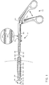
- Figure 1 is a side elevation view, partly in section, of the endoscopic instrument prior to insertion into a trocar tube, and, in partial phantom format, after insertion into a trocar tube;
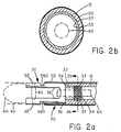
- Figure 2a is a side elevation view, partly in section, of the clevis of the invention in conjunction with the distal end of the tube and shrink wrap of the invention;
- Figure 2b is a cross-section view of the device of Figure 2a;
- Figure 3a is a partially broken-away side elevation view of the actuating handle of the disposable laparoscopic instrument of the invention;
- Figure 3b is a rear elevation view of the device of Figure 3a;
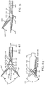
- Figure 4a is a side elevation view, partly in section, of a double acting dissector in conjunction with the clevis and the distal ends of the rod and tube of the endoscopic instrument of the invention, with the staple linkage means shown in perspective and broken out views;
- Figure 4b is a plan view of the device of Figure 4a;
- Figure 4c is an enlarged side view of the connection of the distal end of the rod and the proximal ends of the staple linkage means of Fig. 4a;
- Figures 4d and 4e are enlarged top views of the distal end of the rod and the proximal ends of the staple linkage means when the blades of the the double acting dissector are in open and closed positions respectively; Figure 4f is a side elevation view of a double acting dissector utilizing a crossed staple linkage means;
- Figure 4g is an enlarged top view of the distal end of the rod and the proximal end of the crossed staple linkage means; and
- Figure 5 is a side elevation view of a first embodiment of a single acting scissors of the invention in conjunction with the clevis, and the distal ends of the rod and tube of the disposable laparoscopic instrument of the invention.
- With reference to Figure 1, a disposable endoscopic surgical instrument is indicated at 10. The
disposable instrument 10 broadly comprises analuminum tube 15 surrounded by a peripheral insulating shrink wrap layer ofplastic 20, a clevis means 30,end effectors 40, actuating means 50, and apush rod 60. The clevis means 30 is advantageously a separately formed aluminum piece which fixedly engagesaluminum tube 15 as described in more detail hereinafter. Theclevis 30 also engages theend effectors 40 which are pivotally engaged to clevis 30 atpivot pin 45. Theend effectors 40 are preferably formed of investment cast bronze. Thepush rod 60, which is also formed of aluminum, is engaged at itsdistal end 65 to theend effectors 40, as hereinafter more fully described, and is connected at 70, at its proximal end to a manually operable actuating means 50. For purposes herein, the "distal end" of theinstrument 10 or any part thereof, is the end closest to the surgical site and distant from the surgeon, while the "proximal end" of theinstrument 10 or any part thereof, is the end most proximate the surgeon and distant the surgical site. - In use, the endoscopic/
laparoscopic instrument 10 is inserted with the blades orgraspers end effector 40 in the closed position, intotrocar tube 80, as indicated at thearrow 85 of Figure 1. The distal portion of theinstrument 10 passes through thetrocar tube 80 intobody incision 100. Upon the distal portion of theinstrument 10 exiting thetrocar tube 80, theblades push rod 60 which results from operation of the manual actuating means 50. As is discussed more fully hereinafter, the clevis effectively translates the reciprocal motion of thepush rod 60 into the end effector means action indicated at 105. - Turning to Figures 2a and 2b, a preferred configuration of the
clevis 30 of the present invention is seen. The clevis has a knurled rod-likeproximal portion 34 for mating with the end of thealuminum tube 15, and a post-supporting U-shapeddistal portion 32 for holding the end effector means. The outer diameter of thedistal portion 32 of the clevis is larger than the outer diameter of theproximal portion 34;shoulder 39 being formed therebetween. Theproximal portion 34 of the clevis is preferably hollow, as indicated at 33, to permit thepush rod 60 to extend therethrough. Thedistal portion 32 of theclevis 30 is provided withlegs 36 and a post orpivot pin 45. Thepost 45 is generally perpendicular, i.e. transverse, to thelegs 36 of the clevis and is arranged to extend through hole(s) 39 in the end effector means 40. In this manner, the blades or prongs of the end effector means 40 are held by, but can rotate around, i.e. are rotatably engaged with thepost 45. - As seen in Figure 2a, a recess or notch 380 is provided which extends across each
leg 36 of theclevis 30. Consequently, a peripherally applied electrically insulatingplastic wrap 20 can be end-cut atrecess 380 and a smooth transition from the end effector means 40 via theclevis 30 totube 15 can be achieved. Even if slight outward flaring ofwrap 20 occurs at the end-cut, as is common, this flaring can be tolerated as it will be within the envelope of the normal outer surface indicated at 43. -
Clevis 30 is preferably made from a high strength aluminum base alloy (e.g. 2024 alloy of Alcoa) which is preferably harder than the aluminum base alloy (e.,g. 6061 or 6063 alloys of Alcoa) from whichtube 15 is fabricated. The post portion of the clevis may be made out of the identical alloy or, for added strength, out of a stainless steel nail. In assembly of the laparoscopysurgical instrument 10, serrated orknurled portion 34 ofclevis 10 is fit snugly intotube 15 such that the walls oftube 15 abut theperipheral shoulder 39 ofclevis 30, with the outer surface oftube 15 and the adjacent outer surface ofclevis 30 having essentially the same diameter. Mechanical pressure is then applied totube 15 peripherally at the location ofknurled portion 34, thereby crimping the end portion oftube 15 onto theknurled portion 34. Mechanical pressure causes the projections of the knurls to bite into and firmly engagetube 15 as indicated at 37 due to the higher hardness of the clevis material. Once theclevis 30 andtube 15 have been properly joined, theplastic shrink wrap 20 can be applied over thetube 15 and an adjacent portion of theclevis 30 and end-cut atrecess 380. - With reference to Figures 3a and 3b, manually operable actuating means are indicated at 50 which includes an electrically insulating
housing 914 having a fixedhandle portion 410 integral therewith and alever portion 420 pivotally engaged tohousing 914 atpivot pin 430. Pushrod 60 passes through aluminum tube 15 (covered by shrink wrap 20) and engagescross pin 440 at 454; setscrew 441 being used to extend intocross pin 440 and setpush rod 60 in thecross pin 440. Thecross pin 440 is fixedly positioned inlever member 420. Upon pivotal motion oflever arm 420, as indicated at 450, using a conventional hand grip as indicated at 455 to apply pressure toextended handle element 456 oflever member 420, pushrod 60 will move linearly as indicated at 460 to actuate an end-effector (not shown in Figure 3a) coupled thereto as hereinabove described. There may be occasions, in the course of certain procedures, that certain surgeons will prefer to hold the actuating means 50 in the manner indicated at 465 withfingers grasping housing 914 and thethumb 467 adjacent aportion 470 oflever member 420 which is positioned on the opposite side of cross-pin 440 fromextended handle element 456. Thus, in accord with one aspect of the invention, a roughened knurled orserrated surface 480 is provided integral withportion 470 oflever member 420 to enable a frictional engagement withthumb 467. Utilizingserrated surface 480, when thumb motion as indicated at 490 is initiated, pivotal motion oflever arm 420 is accomplished, as indicated at 450, as is the linear motion ofpush rod 60 as indicated at 460. - Also seen in Fig. 3a is an insulating
ferrule 910 which is designed to extend over and bridge theshrink wrap tubing 20 and thehousing 914 so as to guarantee that all portions of thetube 15 is insulated. Theferrule 910 permits a cautery procedure to be accomplished (see cautery terminal 999) without concern of shock to the surgeon. Also, preferably, theferrule 910 is formed of plastic and is color coded so that a different color is used for each instrument or class of instruments. Thus, for example, scissors may be provided with a red ferrule, while graspers might be provided with a yellow ferrule; clamps with a green ferrule; etc. - With reference to Figures 4a-4g, details are seen of an
end effector 40 and the linkage means for linking theend effector 40 to thepush rod 60. In particular, in Figs. 4a-4g, a double acting dissector is shown withblades 90′, 92′ which are respectively rotatably mounted onpivot pin 45 ofclevis 80′. Eachblade 90′, 92′ of the dissector has a forwardly extending manipulatingportion 94, and a rearwardly extendingplanar base portion 96 with a through-hole 98. Each of the through-holes 98 ofplanar base portions 96 is separately engaged by a separate connecting or linkage means 110, 112. - As shown in Fig. 4a, according to one preferred embodiment, each linkage means 110, 112 is in the form of a thin metal member generally in the shape of an outwardly flared staple. Each linkage means may be generally described as having a
U-shaped section 114 with a base 111 perpendicular to and bridging thearms 118 of the U, and two generally parallel spaced apart outwardly extending side ortab elements 113 which are generally parallel to base 111. Each of the linkage means 110, 112 has one of itstab elements 113 engaged in a through-hole 98 of aplanar base 96, with the U-shaped section of the linkage means extending respectively in opposite directions as illustrated. Theother tab element 113 of the linkage means 110, 112 engage through-holes 120 formed in a flattened plate-like terminal portion 122 of push rod 60 (as seen more clearly in Figs. 4d-4f). As can be seen from Fig. 4a, movement ofpush rod 60 in the direction indicated at 124 will causeblades 90′, 92′ to move in the direction indicated at 127 to theposition 129 without interference between the oppositely positioned staple-like linkage means 110, 112. Correspondingly, thetab elements 113 of the linkage means 110, 112 which extend through the flattenedterminal portion 122 ofpush rod 60 will move from their position shown in Fig. 4d, to the position shown in Fig. 4e. - That manipulators (blades) 90′ and 92′ open and close in response to the axial movement of
push rod 60 may be understood by understanding the relationship of theclevis 30′ and linkage means 110, 112 to theblades 90′, 92′, thepush rod 60, and thetube 15. In particular, due to the fact that theclevis 30′ is rigidly attached to the tube 15 (as described above with reference to Fig. 2a), thetube 15 is a fixed distance from therotation pin 45 of the clevis, and hence to the holes in theblades 90′ and 92′ through whichrotation pin 45 extends. Thus, when thepush rod 60 is moved axially relative to the tube 15 (the tube being fixed in place), the blades of the end effector cannot move axially with the push rod. However, because thepush rod 60 is also a fixed distance away fromholes 98 in the base portion of the end effector blades (due to staple linkage means 110, 112), movement of the push rod relative to the tube must cause movement of theholes 98 in the end effector blades. Because one part each blade is fixed, but another part must move when thepush rod 60 is moved relative to thetube 15,end effector blades post 45 of theclevis 30′ extends. Movement in this manner typically effects a cutting or grasping action. - Figures 4f and 4g show another embodiment of the linkage means which increases the stability of the end effector means 40. In Figures 4g and 4h it is seen that the linkage means 110′, 112′ do not respectively engage the nearest of the through-
holes 120 transversely aligned in the plate-like terminal portion 122 ofpush rod 60, but instead cross-over as indicated at 130. With this arrangement the angle θ, indicated at 135, is increased. The increase in this angle affords a more stable instrument, because the amount of "shake" which results from the unavoidable clearances at thepivot 45 is reduced; i.e., as θ approaches 90°, the amount of free movement at the end of an end-effector blade 90′, 92′ is minimized. - Figure 5 shows a single acting scissors. Essentially, the single acting scissors is identical to the double acting scissors of Figs. 4a-4g except that
blade 692 is stationary; hence no staple is used to connect blade 692 (which may be intregal with the clevis) torod 660. Whileblade 692 is stationary,blade 690 pivots as indicated at 627 aroundpin 645. To ensure rotational movement ofblade 690 upon axial movement ofrod 660, theend 22 ofrod 660 should be supported. - The preferred endoscopic/laparoscopic instruments of the invention are preferably assembled in the following fashion. The
knurled portion 34 of theclevis 30 of the invention is inserted into thealuminum tube 15 which had been previously insert molded in the fixedhandle portion aluminum tube 15 is crimped over theknurls 37 to effect mating. Shrinkwrap 20 is then applied over thealuminum tube 15 and end-cut atgrooves 380 in thearms 36 of theclevis 30.Ferrule 910 is slid over the distal end of thealuminum tube 15, up over the end of thehousing 914, and snapped into place, thereby providing complete insulation. Therod 60,staples holes 39 in the arms of the clevis, therotation post 45, which may either be integral with the clevis, or a separate post or nail, is inserted through the holes in the end effectors, and secured in the holes of the clevis arms such as by tapping. At this point, all that remains to be assembled is the actuating means 50. To assemble the actuating means, across pin 440 is inserted inhandle 420. Handle 420 is then arranged such that thepush rod 60 which extends out of the fixed handle portion will extend through thecross pin 440. Withrod 60 in thecross pin 440, handle 420 is lined up withhandle 410 such that the handlerotation pivot pin 430 can be inserted. Withpivot pin 430 in place, and with the end effectors in the closed position, setscrew 441 is tightened into the cross pin until it bites intorod 60, thereby holdingrod 60 in place relative to crosspin 440. - There has been described and illustrated herein endoscopic instruments. While particular embodiments of the invention have been described, it is not intended that the invention be limited exactly thereto, as it is intended that the invention be as broad in scope as the art will permit. Thus, while particular end effectors were disclosed, it will be appreciated that other end effectors such as, e.g., duckbill graspers, duck-bill dissectors, atraumatic graspers, and traumatic (rat-tooth) graspers, etc., could be utilized. Also, while various materials were described as being preferred for various parts, it will be appreciated that other materials could be utilized. By way of example only, and not by way of limitation, while the tube and clevis are preferably made from aluminum alloys, with the clevis being harder than the tube, if desired, the tube could be harder than the clevis. In such a situation, rather than crimping the tube over the clevis, the clevis could be welded or press fit into the tube. Therefore, it will be apparent to those skilled in the art that other changes and modifications may be made to the invention as described in the specification without departing from the scope of the invention as so claimed.
Claims (18)
- A surgical instrument (10) for insertion through a trocar tube, comprising a reciprocally movable push rod (60) having proximal and distal ends, a pivotally rotatable first end effector (40), and a second end effector (40), an actuating means (50) coupled to said push rod (60) at said proximal end of said push rod (60), an outer tube (15) through which said push rod (60) extends and to which said actuation means (50) is coupled, characterised in that said instrument comprises:coupling means for coupling said push rod (60) and said first end effector (40), said coupling means comprising a unitary resilient staple-like element (110) havinga first terminal portion (113) pivotally engaging a through-hole (120) in the distal portion of said push rod (60),an oppositely extending second terminal portion (113) pivotally engaging a second through-hole (98) in the first end effector (40), anda substantially U-shaped middle portion (114) coupling said first and second terminal portions (113).
- A surgical instrument as claimed in Claim 1 wherein:said push rod (60) has a longitudinal axis, and said unitary resilient staple-like element (110) is angled relative to said longitudinal axis of said push rod (60).
- A surgical instrument as claimed in Claim 1 or Claim 2 wherein:said first (120) and second (98) through-holes are substantially transverse to said longitudinal axis and parallel to each other.
- A surgical instrument as claimed in any one of the preceding Claims wherein:said distal end (122) of said push rod (60) is flattened and includes said through-hole (120) in said distal end of said push rod (60).
- A surgical instrument as claimed in any one of the preceding Claims comprising two pivotally rotatable end effectors (40) and further comprising coupling means for coupling said push rod (60) and said two pivotally rotatable end effectors (40) comprisinga second unitary resilient staple-like element (112) havinga first terminal portion (113) pivotally engaging a second of a pair of through-holes (120) in the push rod (60),an oppositely extending second terminal portion (113) pivotally engaging a through-hole (98) in a second of said two end effectors (40), anda substantially U-shaped middle portion (114) coupling said first and second terminal portions (113) of said second unitary resilient staple-like element (112).
- A surgical instrument as claimed in Claim 5 wherein:said push rod (60) has a longitudinal axis,said first of said pair of through-holes (120) in the push rod (60) is located above said second of said pair of through-holes (120) in the push rod (60) relative to said longitudinal axis,said through-hole (98) in said first of said two end effectors (40) is located below said through-hole (98) in said second of said two end end effectors (40) relative to said longitudinal axis, andsaid first terminal portion (113) of said first unitary resilient staple-like element (110) engages the second of said pair of through-holes (120) in the push rod (60) and the first terminal portion (113) of said second unitary resilient staple-like element (112) engages the first of said pair of through-holes (120) in the push rod (60).
- A surgical instrument as claimed in Claim 5 or Claim 6 wherein:said first (110) and second (112) unitary resilient staple-like elements are both angled relative to the longitudinal axis of said push rod (60).
- A surgical instrument as claimed in Claim 6 or Claim 7 wherein:said pair of through-holes (120) in said push rod (60) and said through-holes (98) in said end effectors (40) are substantially transverse to said longitudinal axis of said push rod (60) and parallel to each other.
- A surgical instrument (10) as claimed in any one of the preceding Claims wherein:a) said outer tube is a hollow tube (15) having a first end and a second end;b) said coupling means further comprises a clevis means (30) separately formed from said tube (15) and mechanically coupled to said first end of said tube (15), said clevis means (30) having first rotation means (45) substantially transverse to said longitudinal axis;c) two end effectors (40) are provided for grasping, cutting, clamping, dissecting, or extracting, one of said end effector (40) having a first hole (39) for receiving said first rotation means (45) and for pivotally engaging said clevis means (30) at said rotation means (45) and a second hole (98) substantially parallel to said first hole (39);d) said push rod (60) extends at least partially through said hollow tube (15) and has a first end and a second end, said rod (60) having a third hole (120);e) a second unitary resilient staple-like element (112) links said first end of said rod (60) with one of said end effectors (40) having said first and second holes, said second unitary resilient staple-like element (112) having a first terminal portion (113) pivotally engaging said third hole (120) of said rod, an oppositely extending second terminal portion (113) pivotally engaging said second hole (98) of said end effector means having said first (39) and second (98) holes, and a substantially U-shaped middle portion (114) coupling said first and second terminal portions (113); andf) said actuating means (50) is engaged to said second end of said rod (60) for imparting reciprocal motion to said rod (60) relative to said tube (15) which is translated at said clevis means (30) to pivotal motion of said end effector (40) having said first (39) and second (98) holes.
- A surgical instrument as claimed in Claim 9, wherein:said hollow tube (15), clevis means (30), and push rod means (60) are formed of aluminium or aluminium base alloys.
- A surgical instrument as claimed in Claim 9 or Claim 10 further comprising:g) shrink wrap plastic (20) covering substantially all of said hollow tube (15), and a portion of said clevis means (30) adjacent the first end of the hollow tube (15).
- A surgical instrument as claimed in Claim 11 wherein:said hollow tube (15) has uniform inner and outer diameters, andsaid clevis means (30) includes a hollow first portion (34) having an inner diameter, and having an outer diameter slightly smaller than said inner diameter of said hollow tube (15), said hollow first portion (34) fitting closely within the hollow tube (15) and fixedly engaging the hollow tube (15), and a second portion (32) having a base section having an outer diameter substantially the same as the outer diameter of the hollow tube (15) and a bore corresponding to the inner diameter of the hollow first portion (34) of the clevis means (30), and a pair of parallel, spaced apart, opposed arm members (36) having respective first and second ends, and integrally joined to said base portion of said clevis means (30) at respective said first ends of said opposed arm members (36), said pair of arm members (36) extending away from said hollow first portion of said clevis means (30), each said opposed arm member (36) having an undercut groove (380) therein along an outer surface of said arm member (36) and substantially transverse said longitudinal axis, wherein said shrink wrap plastic covering (20) terminates in the undercut grooves (380) of the arm members (36).
- A surgical instrument as claimed in Claim 11 or Claim 12 further comprising:a ferrule means (910) for surrounding and covering a terminal portion of said shrink wrap plastic covering (20) and an adjacent portion of said actuating means (50).
- A surgical instrument as claimed in Claim 13, wherein:said actuating means (50) comprises a housing means (914) fixedly engaging said aluminium tube (15), wherein said ferrule means (910) surrounds and covers at least a portion of said housing means (914), and a lever means (420) fixedly engaging said push rod (60) and pivotally engaging said housing means (914), wherein upon pivotal movement of said lever means (420) reciprocal motion is imparted to said push rod (60).
- A surgical instrument as claimed in Claim 14, wherein:said actuating means (50) further comprises a handle means (456) fixedly attached to said housing means (914) to cooperate with said lever means (420) in providing pivotal movement of said lever means (420) where said handle (456) and lever means (420) are squeezed by a human hand.
- A surgical instrument as claimed in any one of Claims 1 to 12, wherein:said actuating means (50) comprises a housing means (914) fixedly engaging said outer tube (15), a lever means (420) fixedly engaging said push rod (60) and pivotally engaging said housing means (914), and a handle means (456) fixedly attached to said housing means (914), wherein pivotal movement of said said lever means (420) imparts reciprocal motion to said push rod (60), and wherein said handle means (456) cooperates with said lever means (420) in providing pivotal movement of said lever means (420) where said handle (456) and lever (420) means are squeezed by a human hand.
- A surgical instrument as claimed in any one of Claims 9 to 16 wherein:said first end of said rod (60) has a plate-like portion (122) having said third hole (120) and a fourth hole (120) spaced from said third hole (120),each of said end effectors (40) has a respective first hole (39) for receiving said first rotation means (45) and for pivotally engaging said clevis means (30) at said rotation means (45), and a respective second hole (98) substantially parallel to said first hole, andsaid surgical instrument comprises a second unitary resilient staple-like element (112) linking said first end of said rod (60) with one of said end effectors (40), with one of said unitary resilient staple-like connecting means (110) engaging said third hole (120), of said rod, and the other of said unitary resilient staple-like elements (112) engaging said fourth hole (120) of said rod.
- A surgical instrument as claimed in Claim 17, wherein:said first and second elements (110, 112) which engage respective through-holes (120) of the plate-like portion (122) of said push rod (60) are positioned to cross each other.
Applications Claiming Priority (4)
| Application Number | Priority Date | Filing Date | Title |
|---|---|---|---|
| US680399 | 1984-12-11 | ||
| US07/680,392 US5192298A (en) | 1990-05-10 | 1991-04-04 | Disposable laparoscopic surgical instruments |
| US680392 | 1991-04-04 | ||
| US07/680,399 US5141519A (en) | 1990-05-10 | 1991-04-04 | Connecting elements for connecting push rod to end effectors in a disposable laparoscopic surgical instrument |
Publications (2)
| Publication Number | Publication Date |
|---|---|
| EP0507622A1 EP0507622A1 (en) | 1992-10-07 |
| EP0507622B1 true EP0507622B1 (en) | 1997-09-17 |
Family
ID=27102446
Family Applications (1)
| Application Number | Title | Priority Date | Filing Date |
|---|---|---|---|
| EP92302984A Expired - Lifetime EP0507622B1 (en) | 1991-04-04 | 1992-04-03 | Endoscopic surgical instruments |
Country Status (5)
| Country | Link |
|---|---|
| EP (1) | EP0507622B1 (en) |
| JP (1) | JP2573771B2 (en) |
| CA (1) | CA2065089C (en) |
| DE (1) | DE69222216T2 (en) |
| IL (1) | IL101493A (en) |
Cited By (12)
| Publication number | Priority date | Publication date | Assignee | Title |
|---|---|---|---|---|
| US5944715A (en) | 1996-06-20 | 1999-08-31 | Gyrus Medical Limited | Electrosurgical instrument |
| US6004319A (en) | 1995-06-23 | 1999-12-21 | Gyrus Medical Limited | Electrosurgical instrument |
| US6013076A (en) | 1996-01-09 | 2000-01-11 | Gyrus Medical Limited | Electrosurgical instrument |
| US6015406A (en) | 1996-01-09 | 2000-01-18 | Gyrus Medical Limited | Electrosurgical instrument |
| US6027501A (en) | 1995-06-23 | 2000-02-22 | Gyrus Medical Limited | Electrosurgical instrument |
| US6090106A (en) | 1996-01-09 | 2000-07-18 | Gyrus Medical Limited | Electrosurgical instrument |
| US6093186A (en) | 1996-12-20 | 2000-07-25 | Gyrus Medical Limited | Electrosurgical generator and system |
| US6210405B1 (en) | 1996-06-20 | 2001-04-03 | Gyrus Medical Limited | Under water treatment |
| US6261286B1 (en) | 1995-06-23 | 2001-07-17 | Gyrus Medical Limited | Electrosurgical generator and system |
| US6277114B1 (en) | 1998-04-03 | 2001-08-21 | Gyrus Medical Limited | Electrode assembly for an electrosurical instrument |
| US6565561B1 (en) | 1996-06-20 | 2003-05-20 | Cyrus Medical Limited | Electrosurgical instrument |
| US6780180B1 (en) | 1995-06-23 | 2004-08-24 | Gyrus Medical Limited | Electrosurgical instrument |
Families Citing this family (9)
| Publication number | Priority date | Publication date | Assignee | Title |
|---|---|---|---|---|
| US5234453A (en) * | 1990-05-10 | 1993-08-10 | Symblosis Corporation | Cobalt base alloy end effectors for laparoscopic surgical scissors |
| GB9309142D0 (en) * | 1993-05-04 | 1993-06-16 | Gyrus Medical Ltd | Laparoscopic instrument |
| DE4318951C1 (en) * | 1993-05-25 | 1994-12-22 | Ethicon Endo Surgery Europe | Endoscopic gripping instrument |
| DE19707374C2 (en) * | 1997-02-25 | 2000-10-26 | Storz Karl Gmbh & Co Kg | Medical dissection spatula with expandable spatula jaw parts |
| ITCE990004A1 (en) * | 1999-10-25 | 2000-01-25 | Mario Immacolato Paternuosto | VALVE FOR BIOPSY FORCEPS IN DIGESTIVE ENDOSCOPY |
| US7837631B2 (en) | 2003-03-14 | 2010-11-23 | Boston Scientific Scimed Inc. | Biopsy forceps with removable jaw segments |
| JP4829005B2 (en) * | 2006-05-12 | 2011-11-30 | テルモ株式会社 | manipulator |
| CN101686838A (en) * | 2007-06-05 | 2010-03-31 | 马塞拉·卡德纳斯 | The Medical Instruments that is used for abdominal cavity and pelvioscopy and operation |
| DE102010011926A1 (en) * | 2010-03-18 | 2011-09-22 | Olympus Winter & Ibe Gmbh | Laparoscopic needle holder |
Citations (2)
| Publication number | Priority date | Publication date | Assignee | Title |
|---|---|---|---|---|
| US3895636A (en) * | 1973-09-24 | 1975-07-22 | William Schmidt | Flexible forceps |
| US4369788A (en) * | 1980-01-31 | 1983-01-25 | Goald Harold J | Reversed forceps for microdisc surgery |
Family Cites Families (2)
| Publication number | Priority date | Publication date | Assignee | Title |
|---|---|---|---|---|
| US5133727A (en) * | 1990-05-10 | 1992-07-28 | Symbiosis Corporation | Radial jaw biopsy forceps |
| US4880015A (en) * | 1988-06-03 | 1989-11-14 | Nierman David M | Biopsy forceps |
-
1992
- 1992-04-03 CA CA002065089A patent/CA2065089C/en not_active Expired - Fee Related
- 1992-04-03 IL IL10149392A patent/IL101493A/en not_active IP Right Cessation
- 1992-04-03 EP EP92302984A patent/EP0507622B1/en not_active Expired - Lifetime
- 1992-04-03 DE DE69222216T patent/DE69222216T2/en not_active Expired - Fee Related
- 1992-04-04 JP JP4082540A patent/JP2573771B2/en not_active Expired - Fee Related
Patent Citations (2)
| Publication number | Priority date | Publication date | Assignee | Title |
|---|---|---|---|---|
| US3895636A (en) * | 1973-09-24 | 1975-07-22 | William Schmidt | Flexible forceps |
| US4369788A (en) * | 1980-01-31 | 1983-01-25 | Goald Harold J | Reversed forceps for microdisc surgery |
Non-Patent Citations (4)
| Title |
|---|
| US-A- 3 895 636 * |
| US-A- 4 369 788 * |
| WO-A-89/11827 * |
| WO-A-91/16856 * |
Cited By (18)
| Publication number | Priority date | Publication date | Assignee | Title |
|---|---|---|---|---|
| US6174308B1 (en) | 1995-06-23 | 2001-01-16 | Gyrus Medical Limited | Electrosurgical instrument |
| US6364877B1 (en) | 1995-06-23 | 2002-04-02 | Gyrus Medical Limited | Electrosurgical generator and system |
| US6416509B1 (en) | 1995-06-23 | 2002-07-09 | Gyrus Medical Limited | Electrosurgical generator and system |
| US6004319A (en) | 1995-06-23 | 1999-12-21 | Gyrus Medical Limited | Electrosurgical instrument |
| US6027501A (en) | 1995-06-23 | 2000-02-22 | Gyrus Medical Limited | Electrosurgical instrument |
| US6056746A (en) | 1995-06-23 | 2000-05-02 | Gyrus Medical Limited | Electrosurgical instrument |
| US6261286B1 (en) | 1995-06-23 | 2001-07-17 | Gyrus Medical Limited | Electrosurgical generator and system |
| US6780180B1 (en) | 1995-06-23 | 2004-08-24 | Gyrus Medical Limited | Electrosurgical instrument |
| US6013076A (en) | 1996-01-09 | 2000-01-11 | Gyrus Medical Limited | Electrosurgical instrument |
| US6015406A (en) | 1996-01-09 | 2000-01-18 | Gyrus Medical Limited | Electrosurgical instrument |
| US6090106A (en) | 1996-01-09 | 2000-07-18 | Gyrus Medical Limited | Electrosurgical instrument |
| US6234178B1 (en) | 1996-01-09 | 2001-05-22 | Gyrus Medical Limited | Electrosurgical instrument |
| US6210405B1 (en) | 1996-06-20 | 2001-04-03 | Gyrus Medical Limited | Under water treatment |
| US6482202B1 (en) | 1996-06-20 | 2002-11-19 | Gyrus Medical Limited | Under water treatment |
| US6565561B1 (en) | 1996-06-20 | 2003-05-20 | Cyrus Medical Limited | Electrosurgical instrument |
| US5944715A (en) | 1996-06-20 | 1999-08-31 | Gyrus Medical Limited | Electrosurgical instrument |
| US6093186A (en) | 1996-12-20 | 2000-07-25 | Gyrus Medical Limited | Electrosurgical generator and system |
| US6277114B1 (en) | 1998-04-03 | 2001-08-21 | Gyrus Medical Limited | Electrode assembly for an electrosurical instrument |
Also Published As
| Publication number | Publication date |
|---|---|
| DE69222216T2 (en) | 1998-03-19 |
| CA2065089C (en) | 1995-02-07 |
| JP2573771B2 (en) | 1997-01-22 |
| IL101493A0 (en) | 1992-12-30 |
| EP0507622A1 (en) | 1992-10-07 |
| JPH0591974A (en) | 1993-04-16 |
| IL101493A (en) | 1995-10-31 |
| DE69222216D1 (en) | 1997-10-23 |
Similar Documents
| Publication | Publication Date | Title |
|---|---|---|
| EP0507621B1 (en) | Thumb-activated actuating member for endoscopic surgical instrument | |
| US5331971A (en) | Endoscopic surgical instruments | |
| EP0507620B1 (en) | Investment cast end effectors for disposable endoscopic surgical instrument | |
| US5192298A (en) | Disposable laparoscopic surgical instruments | |
| US5156633A (en) | Maryland dissector laparoscopic instrument | |
| US5171256A (en) | Single acting disposable laparoscopic scissors | |
| EP0507622B1 (en) | Endoscopic surgical instruments | |
| US5170800A (en) | Hermaphroditic endoscopic claw extractors | |
| US5342390A (en) | Thumb-activated actuating member for imparting reciprocal motion to a push rod of a disposable laparoscopic surgical instrument | |
| US5275612A (en) | Insulating ferrule for disposable laparoscopic surgical instrument | |
| US5241968A (en) | Single acting endoscopic instruments | |
| US5269804A (en) | Endoscopic colo-rectal bowel clamp | |
| US5258004A (en) | Double acting, dual pivot thoracoscopic surgical lung clamps | |
| AU655327B2 (en) | Double acting, dual pivot disposable endoscopic surgical instruments | |
| WO1992017115A1 (en) | Clevis for endoscopic surgical instrument | |
| AU647349B2 (en) | Endoscopic surgical instruments | |
| AU654646B2 (en) | Endoscopic surgical instrument | |
| IL101494A (en) | Thumb activated actuating member for imparting reciprocal motion to push rod of an endoscopic surgical instrument | |
| IL103484A (en) | Double acting dual pivot disposable laparoscopic surgical instruments |
Legal Events
| Date | Code | Title | Description |
|---|---|---|---|
| PUAI | Public reference made under article 153(3) epc to a published international application that has entered the european phase |
Free format text: ORIGINAL CODE: 0009012 |
|
| AK | Designated contracting states |
Kind code of ref document: A1 Designated state(s): DE ES FR GB IT NL |
|
| RIN1 | Information on inventor provided before grant (corrected) |
Inventor name: BOX, JOHN WILLIAM Inventor name: BALES, THOMAS O. Inventor name: SMITH, KEVIN W. Inventor name: SCARFONE, FRANK A. Inventor name: SLATER, CHARLES R. Inventor name: MURPHY, GREGORY J. |
|
| RIN1 | Information on inventor provided before grant (corrected) |
Inventor name: SCARFONE, FRANK A. Inventor name: BALES, THOMAS O. Inventor name: MURPHY, GREGORY J. Inventor name: SLATER, CHARLES R. Inventor name: SMITH, KEVIN W. Inventor name: BOX, JOHN WILLIAM |
|
| 17P | Request for examination filed |
Effective date: 19930323 |
|
| 17Q | First examination report despatched |
Effective date: 19950112 |
|
| GRAG | Despatch of communication of intention to grant |
Free format text: ORIGINAL CODE: EPIDOS AGRA |
|
| GRAH | Despatch of communication of intention to grant a patent |
Free format text: ORIGINAL CODE: EPIDOS IGRA |
|
| GRAH | Despatch of communication of intention to grant a patent |
Free format text: ORIGINAL CODE: EPIDOS IGRA |
|
| GRAA | (expected) grant |
Free format text: ORIGINAL CODE: 0009210 |
|
| AK | Designated contracting states |
Kind code of ref document: B1 Designated state(s): DE ES FR GB IT NL |
|
| PG25 | Lapsed in a contracting state [announced via postgrant information from national office to epo] |
Ref country code: IT Free format text: LAPSE BECAUSE OF FAILURE TO SUBMIT A TRANSLATION OF THE DESCRIPTION OR TO PAY THE FEE WITHIN THE PRE;WARNING: LAPSES OF ITALIAN PATENTS WITH EFFECTIVE DATE BEFORE 2007 MAY HAVE OCCURRED AT ANY TIME BEFORE 2007. THE CORRECT EFFECTIVE DATE MAY BE DIFFERENT FROM THE ONE RECORDED.SCRIBED TIME-LIMIT Effective date: 19970917 Ref country code: NL Free format text: LAPSE BECAUSE OF FAILURE TO SUBMIT A TRANSLATION OF THE DESCRIPTION OR TO PAY THE FEE WITHIN THE PRESCRIBED TIME-LIMIT Effective date: 19970917 Ref country code: ES Free format text: THE PATENT HAS BEEN ANNULLED BY A DECISION OF A NATIONAL AUTHORITY Effective date: 19970917 |
|
| REF | Corresponds to: |
Ref document number: 69222216 Country of ref document: DE Date of ref document: 19971023 |
|
| ET | Fr: translation filed | ||
| NLV1 | Nl: lapsed or annulled due to failure to fulfill the requirements of art. 29p and 29m of the patents act | ||
| PG25 | Lapsed in a contracting state [announced via postgrant information from national office to epo] |
Ref country code: GB Free format text: LAPSE BECAUSE OF NON-PAYMENT OF DUE FEES Effective date: 19980403 |
|
| PLBE | No opposition filed within time limit |
Free format text: ORIGINAL CODE: 0009261 |
|
| STAA | Information on the status of an ep patent application or granted ep patent |
Free format text: STATUS: NO OPPOSITION FILED WITHIN TIME LIMIT |
|
| 26N | No opposition filed | ||
| GBPC | Gb: european patent ceased through non-payment of renewal fee |
Effective date: 19980403 |
|
| PGFP | Annual fee paid to national office [announced via postgrant information from national office to epo] |
Ref country code: FR Payment date: 20090406 Year of fee payment: 18 Ref country code: DE Payment date: 20090430 Year of fee payment: 18 |
|
| REG | Reference to a national code |
Ref country code: FR Ref legal event code: ST Effective date: 20101230 |
|
| PG25 | Lapsed in a contracting state [announced via postgrant information from national office to epo] |
Ref country code: DE Free format text: LAPSE BECAUSE OF NON-PAYMENT OF DUE FEES Effective date: 20101103 |
|
| PG25 | Lapsed in a contracting state [announced via postgrant information from national office to epo] |
Ref country code: FR Free format text: LAPSE BECAUSE OF NON-PAYMENT OF DUE FEES Effective date: 20100430 |