EP0446979B1 - System for transmitting alarm signals with a repetition - Google Patents
System for transmitting alarm signals with a repetition Download PDFInfo
- Publication number
- EP0446979B1 EP0446979B1 EP91200381A EP91200381A EP0446979B1 EP 0446979 B1 EP0446979 B1 EP 0446979B1 EP 91200381 A EP91200381 A EP 91200381A EP 91200381 A EP91200381 A EP 91200381A EP 0446979 B1 EP0446979 B1 EP 0446979B1
- Authority
- EP
- European Patent Office
- Prior art keywords
- transmitting
- transmitting unit
- delay time
- identification code
- circuit
- Prior art date
- Legal status (The legal status is an assumption and is not a legal conclusion. Google has not performed a legal analysis and makes no representation as to the accuracy of the status listed.)
- Expired - Lifetime
Links
Images
Classifications
-
- G—PHYSICS
- G08—SIGNALLING
- G08B—SIGNALLING OR CALLING SYSTEMS; ORDER TELEGRAPHS; ALARM SYSTEMS
- G08B25/00—Alarm systems in which the location of the alarm condition is signalled to a central station, e.g. fire or police telegraphic systems
- G08B25/01—Alarm systems in which the location of the alarm condition is signalled to a central station, e.g. fire or police telegraphic systems characterised by the transmission medium
- G08B25/10—Alarm systems in which the location of the alarm condition is signalled to a central station, e.g. fire or police telegraphic systems characterised by the transmission medium using wireless transmission systems
Definitions
- the invention relates to a system as claimed in the precharacterizing portion of claim 1.
- the activation device is a switch to be operated by a user of the transmitting unit.
- the delay times of all the transmitting units are different. This is intended to reduce the possibility that alarm signals transmitted by different transmitting units overlap one another and thereby interfere with their reception in the central receiver if the users of said transmitting units operate the switch of their transmitting unit approximately at the same instant. Operation of the switch approximately simultaneously may occur, for example, in an alert situation which is observed by different users of such transmitting units. In this connection, depending on the use of the system, a very serious situation may arise if none of the alarm signals transmitted approximately simultaneously is received well by the central receiver.
- EP-A-0 368 710 The delay time is derived from the transmitting unit's identification code.
- the known system has the drawback that a large number of different delay times, which therefore comprise a number of relatively long delay times, has to be used, as a result of which it may be a relatively long time before a transmission of an alarm signal is repeated, and this is very undesirable in some alert situations.
- the invention is based on the insight that in practice certain situations are monitored essentially by a certain group of users of portable alarm transmission units, as a result of which it may be sufficient in practice that only the delay times of the transmission units of the users of such a particular group are different.
- the object of the invention is to provide a solution to this problem.
- the delay time depends on the least-significant section of the identification code.
- a simple implementation can be obtained in which a value of an elapsed section of the delay time is compared with the least-significant section and in which the delay is terminated in the event of equality.
- the delay time can also be determined by processing the identification code with a predetermined algorithm.
- sections of the identification code can be processed arithmetically in a manner such that the delay times of the transmitting units of the predetermined group are different with a relatively high reliability.
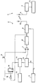
- the drawing shows a central receiver 1 and a portable transmitting unit 2 of a number of portable transmitting units 2 of the system according to the invention.
- the central receiver 1 comprises a receiving circuit 3 to which an aerial 4 is connected and which has an output which is connected to an input of a processing system 5.
- the processing system 5 may be a simple circuit for generating an attention signal on receipt of an alarm signal by the receiving circuit 3 or it may be a telephone exchange for transmitting an alarm signal received or it may comprise a computer for processing an alarm signal received.
- the embodiment shown in the drawing of the portable transmitting unit 2 comprises a switch 6 which is intended to be operated by the user of the transmitting unit 2, and one terminal of which is connected to a point having a logically high ("1") level and another terminal of which is connected to an input of an OR gate 7.
- An output of the OR gate 7 is connected to a trigger input of a monostable multivibrator 8 which is triggered by a rising edge of the signal supplied to the trigger input thereof and, in response thereto, delivers a signal having a logically high level for a predetermined time to an output.
- the output of the monostable multivibrator 8 is connected to a transmitting circuit 9 which is connected to an aerial 10.
- a group of inputs of the transmitting circuit 9 receives an identification code or identification number allocated to the transmitting unit 2 and stored in a register 11 via n lines. If the signal delivered by the monostable multivibrator 8 to the transmitting circuit 9 is logically high, the transmitting circuit 9 transmits an alarm signal which contains the identification code.
- the output of the monostable multivibrator 8 is also connected via an inverter 12 to a clock input of a JK flip-flop 13 which is triggered at rising edges of the signal delivered at its clock input.
- the J input and the K input are each connected to the source having a logically high level.
- An inverting output Q of the flip-flop 13 is connected to a reset input of a counting circuit 14.
- the Q output of the flip-flop 13 On initialisation of the transmitting unit 2 and in the quiescent state of the transmitting unit 2, the Q output of the flip-flop 13 has a logically high level, in which case it holds the counting circuit 14 at the counter reading 0, or in general, at an initial reading.
- a clock input of the counting circuit 14 is connected to an output of a clock generator 15.
- a group of outputs for the counter reading of the counting circuit 14 is connected to a corresponding group of inputs of a comparator 16, another group of inputs of which is connected to a number m of lines having consecutive, in particular least-significant values of the n lines which are connected to the outputs of the register 11.
- the monostable multivibrator 8 is triggered and its output signal consequently becomes high, as a result of which the transmitting circuit 9 transmits an alarm signal which contains the identification code read out of the register 11.
- the output signal of the monostable multivibrator 8 becomes low, thereby triggering the JK flip-flop 13, as a result of which the inverting output Q becomes low and the counting circuit 14 is consequently able to count the clock pulses received from the clock generator 15.
- the comparator 16 delivers an output signal having a high level, as a result of which the monostable multivibrator 8 is again triggered and the transmitting circuit 9 will consequently transmit the same alarm signal yet again.
- the flip-flop 13 When the output signal of the monostable multivibrator 8 becomes low for the second time after the operation of the switch 6, the flip-flop 13 is triggered for the second time, as a result of which the flip-flop 13 returns to its state in which its inverting output Q is high, thereby resetting the counting circuit 14 to zero. The transmitting unit 2 is then back in the quiescent state.
- the maximum delay time which can be obtained by means of the embodiment of the transmitting unit 2 shown depends on the number m of inputs of the comparator 16 which are connected to the register 11. The smallest difference between the various delay times is at the same time equal to the period of the clock pulses delivered by the clock generator 15.
- the period of the clock pulses generated by the clock generator 15 must be at least as great as the transmitting time of an alarm signal, which at most lasts as long as the time predetermined by the monostable multivibrator 8 for which its output is high.
- the identification code or the identification number in the register 11 can have binary-decimal coding.
- the numbers m and n are then multiples of 4 and a BCD counter is then chosen for the counting circuit 14.
- the m lines do not have to be lines having consecutive order numbers.
- a condition is only that the m lines for different transmitting units of a predetermined group of transmitting units indicate different values.
- a start pulse occurring at the start of the propagation and a finish pulse occurring at the end of the transmission which are delivered, for example, by an asynchronous transmitting circuit, known per se, having a binary parallel/series converter, may also be used.
- the transmitting unit 2 may comprise a microprocessor, as a result of which the invention can also be implemented by using a suitable program.
Description
- The invention relates to a system as claimed in the precharacterizing portion of claim 1.
- A system of this type is disclosed by the US Patent Specification 4,347,501. In the known system, the activation device is a switch to be operated by a user of the transmitting unit. The delay times of all the transmitting units are different. This is intended to reduce the possibility that alarm signals transmitted by different transmitting units overlap one another and thereby interfere with their reception in the central receiver if the users of said transmitting units operate the switch of their transmitting unit approximately at the same instant. Operation of the switch approximately simultaneously may occur, for example, in an alert situation which is observed by different users of such transmitting units. In this connection, depending on the use of the system, a very serious situation may arise if none of the alarm signals transmitted approximately simultaneously is received well by the central receiver. A similar system is known from EP-A-0 368 710. The delay time is derived from the transmitting unit's identification code.
- The known system has the drawback that a large number of different delay times, which therefore comprise a number of relatively long delay times, has to be used, as a result of which it may be a relatively long time before a transmission of an alarm signal is repeated, and this is very undesirable in some alert situations.
- The invention is based on the insight that in practice certain situations are monitored essentially by a certain group of users of portable alarm transmission units, as a result of which it may be sufficient in practice that only the delay times of the transmission units of the users of such a particular group are different.
- The object of the invention is to provide a solution to this problem.
- For this purpose, the system of the type mentioned in the preamble, according to the invention is characterised by the features claimed in the characterizing portion of claim 1.
- This ensures in a simple way that the delay times of such a predetermined group of transmitting units are different and, consequently, that the overlapping transmission of alarm signals by the transmitting units of the group is expediently counteracted. The number of different delay times of all the transmitting units of the system can in this case be small and the delay times can be kept relatively short.
- If the least-significant sections of the identification codes of the predetermined group of transmitting units are different, in particular because consecutive identification numbers have been given to said transmitting units, it is beneficial if the delay time depends on the least-significant section of the identification code. As a result of this, a simple implementation can be obtained in which a value of an elapsed section of the delay time is compared with the least-significant section and in which the delay is terminated in the event of equality.
- The delay time can also be determined by processing the identification code with a predetermined algorithm. In this case, sections of the identification code can be processed arithmetically in a manner such that the delay times of the transmitting units of the predetermined group are different with a relatively high reliability.
- The invention is explained with reference to the drawing.
- The drawing shows a central receiver 1 and a portable transmitting unit 2 of a number of portable transmitting units 2 of the system according to the invention. The central receiver 1 comprises a
receiving circuit 3 to which an aerial 4 is connected and which has an output which is connected to an input of a processing system 5. The processing system 5 may be a simple circuit for generating an attention signal on receipt of an alarm signal by thereceiving circuit 3 or it may be a telephone exchange for transmitting an alarm signal received or it may comprise a computer for processing an alarm signal received. - The embodiment shown in the drawing of the portable transmitting unit 2 comprises a
switch 6 which is intended to be operated by the user of the transmitting unit 2, and one terminal of which is connected to a point having a logically high ("1") level and another terminal of which is connected to an input of an OR gate 7. An output of the OR gate 7 is connected to a trigger input of a monostable multivibrator 8 which is triggered by a rising edge of the signal supplied to the trigger input thereof and, in response thereto, delivers a signal having a logically high level for a predetermined time to an output. The output of the monostable multivibrator 8 is connected to a transmitting circuit 9 which is connected to an aerial 10. A group of inputs of the transmitting circuit 9 receives an identification code or identification number allocated to the transmitting unit 2 and stored in a register 11 via n lines. If the signal delivered by the monostable multivibrator 8 to the transmitting circuit 9 is logically high, the transmitting circuit 9 transmits an alarm signal which contains the identification code. - The output of the monostable multivibrator 8 is also connected via an
inverter 12 to a clock input of a JK flip-flop 13 which is triggered at rising edges of the signal delivered at its clock input. The J input and the K input are each connected to the source having a logically high level. An inverting outputQ of the flip-flop 13 is connected to a reset input of acounting circuit 14. On initialisation of the transmitting unit 2 and in the quiescent state of the transmitting unit 2, theQ output of the flip-flop 13 has a logically high level, in which case it holds the countingcircuit 14 at the counter reading 0, or in general, at an initial reading. - A clock input of the
counting circuit 14 is connected to an output of aclock generator 15. A group of outputs for the counter reading of thecounting circuit 14 is connected to a corresponding group of inputs of acomparator 16, another group of inputs of which is connected to a number m of lines having consecutive, in particular least-significant values of the n lines which are connected to the outputs of the register 11. - Starting from an initialisation state or quiescent state of the transmitting unit 2, its operation is as follows:
- If the user of the transmitting unit 2 operates the
switch 6, the monostable multivibrator 8 is triggered and its output signal consequently becomes high, as a result of which the transmitting circuit 9 transmits an alarm signal which contains the identification code read out of the register 11. - After the transmission has elapsed, in particular after the elapse of the time predetermined by the monostable multivibrator 8, the output signal of the monostable multivibrator 8 becomes low, thereby triggering the JK flip-flop 13, as a result of which the inverting output
Q becomes low and the countingcircuit 14 is consequently able to count the clock pulses received from theclock generator 15. - If the counter reading of the
counting circuit 14 is equal to the value which is presented by the m inputs of thecomparator 16 which are connected to the register 11, thecomparator 16 delivers an output signal having a high level, as a result of which the monostable multivibrator 8 is again triggered and the transmitting circuit 9 will consequently transmit the same alarm signal yet again. - When the output signal of the monostable multivibrator 8 becomes low for the second time after the operation of the
switch 6, the flip-flop 13 is triggered for the second time, as a result of which the flip-flop 13 returns to its state in which its inverting outputQ is high, thereby resetting the countingcircuit 14 to zero. The transmitting unit 2 is then back in the quiescent state. - The maximum delay time which can be obtained by means of the embodiment of the transmitting unit 2 shown depends on the number m of inputs of the
comparator 16 which are connected to the register 11. The smallest difference between the various delay times is at the same time equal to the period of the clock pulses delivered by theclock generator 15. In order to counteract overlapping of alarm signals transmitted by different transmitting units 2, the period of the clock pulses generated by theclock generator 15 must be at least as great as the transmitting time of an alarm signal, which at most lasts as long as the time predetermined by the monostable multivibrator 8 for which its output is high. - It is pointed out that the identification code or the identification number in the register 11 can have binary-decimal coding. The numbers m and n are then multiples of 4 and a BCD counter is then chosen for the
counting circuit 14. - As an alternative, the m lines do not have to be lines having consecutive order numbers. A condition is only that the m lines for different transmitting units of a predetermined group of transmitting units indicate different values.
- Within the scope of the invention it is also possible to process the sections of the identification code or the identification number of a transmitting unit with a predetermined algorithm, with, for example, addition of figures, and to make the delay time dependent on a result following from the processing.
- Instead of using a monostable multivibrator to determine the start and the finish of a transmission, a start pulse occurring at the start of the propagation and a finish pulse occurring at the end of the transmission which are delivered, for example, by an asynchronous transmitting circuit, known per se, having a binary parallel/series converter, may also be used.
- Finally, it is pointed out that the transmitting unit 2 may comprise a microprocessor, as a result of which the invention can also be implemented by using a suitable program.
Claims (3)
- System for transmitting alarm signals comprising at least one portable transmitting unit and one central receiver, the transmitting unit comprising a control circuit which is connected to an activation device and a transmitting circuit, the control circuit activating the transmitting circuit when the activation device is energised in order to transmit an alarm signal and in order to re-activate the transmitting circuit for the re-transmission of the alarm signal after the elapse of a delay time, the delay time being different from a delay time of at least one other transmitting unit and being derived from its identification code, the transmitting unit having a memory for storing the identification code allocated to the transmitting unit, the central receiver comprising a processing system which is connected to a receiving circuit which is suitable for receiving an alarm signal and the processing circuit activating a signalling device, on receipt of an alarm signal, for the purpose of generating an attention signal, characterised in that the delay time is dependent on a corresponding section only of the identification code, these sections of the identification codes of the transmitting units to be allocated to a predetermined group of users likely to react to the same event having different values, whereas at least one of the sections has the same value as the corresponding section of the identification code of a transmitting unit to be allocated to a user in at least one other predetermined group of users.
- System according to claim 2, characterised in that the least-significant sections of the identification codes of transmitting units of the predetermined group are different, and in that the delay time is dependent on the least-significant section.
- System according to claim 1 or 2, characterised in that the delay time is determined by processing the identification code with a predetermined algorithm.
Applications Claiming Priority (2)
| Application Number | Priority Date | Filing Date | Title |
|---|---|---|---|
| NL9000606 | 1990-03-16 | ||
| NL9000606A NL9000606A (en) | 1990-03-16 | 1990-03-16 | SYSTEM FOR THE TRANSMISSION OF ALARM SIGNALS. |
Publications (2)
| Publication Number | Publication Date |
|---|---|
| EP0446979A1 EP0446979A1 (en) | 1991-09-18 |
| EP0446979B1 true EP0446979B1 (en) | 1994-12-07 |
Family
ID=19856752
Family Applications (1)
| Application Number | Title | Priority Date | Filing Date |
|---|---|---|---|
| EP91200381A Expired - Lifetime EP0446979B1 (en) | 1990-03-16 | 1991-02-21 | System for transmitting alarm signals with a repetition |
Country Status (4)
| Country | Link |
|---|---|
| US (1) | US5164704A (en) |
| EP (1) | EP0446979B1 (en) |
| DE (1) | DE69105561T2 (en) |
| NL (1) | NL9000606A (en) |
Cited By (1)
| Publication number | Priority date | Publication date | Assignee | Title |
|---|---|---|---|---|
| US6700902B1 (en) | 1998-10-19 | 2004-03-02 | Elster Electricity, Llc | Method and system for improving wireless data packet delivery |
Families Citing this family (23)
| Publication number | Priority date | Publication date | Assignee | Title |
|---|---|---|---|---|
| EP0638878B1 (en) * | 1991-10-11 | 1997-05-07 | Advanced Mining Software Limited | Location system |
| AU668968B2 (en) * | 1993-08-10 | 1996-05-23 | Advanced Mining Software Limited | Location system |
| DE4243026C2 (en) * | 1992-12-18 | 1994-10-13 | Grundig Emv | Radio alarm system with asynchronous transmission of messages via time channels of different periods |
| US5635907A (en) * | 1993-08-10 | 1997-06-03 | Bernard; Hermanus A. | Location system |
| AP449A (en) * | 1993-08-11 | 1996-01-18 | Advanced Mining Software Ltd | Location systems for tracking personnel. |
| US5708417A (en) * | 1993-12-16 | 1998-01-13 | Phone Alert Corp. | Monitoring system for remote units |
| US7095019B1 (en) | 2003-05-30 | 2006-08-22 | Chem-Space Associates, Inc. | Remote reagent chemical ionization source |
| JP4030471B2 (en) * | 2003-06-06 | 2008-01-09 | 日本テキサス・インスツルメンツ株式会社 | Pulse signal generation circuit |
| US7742430B2 (en) | 2004-09-24 | 2010-06-22 | Elster Electricity, Llc | System for automated management of spontaneous node migration in a distributed fixed wireless network |
| US7702594B2 (en) | 2004-09-24 | 2010-04-20 | Elster Electricity, Llc | System and method for automated configuration of meters |
| US20060109103A1 (en) * | 2004-11-11 | 2006-05-25 | Robert Bradus | Transmission technique for a portable alarm system |
| US7138626B1 (en) | 2005-05-05 | 2006-11-21 | Eai Corporation | Method and device for non-contact sampling and detection |
| US7568401B1 (en) | 2005-06-20 | 2009-08-04 | Science Applications International Corporation | Sample tube holder |
| US7576322B2 (en) | 2005-11-08 | 2009-08-18 | Science Applications International Corporation | Non-contact detector system with plasma ion source |
| US8073384B2 (en) | 2006-12-14 | 2011-12-06 | Elster Electricity, Llc | Optimization of redundancy and throughput in an automated meter data collection system using a wireless network |
| US8320302B2 (en) | 2007-04-20 | 2012-11-27 | Elster Electricity, Llc | Over the air microcontroller flash memory updates |
| US8123396B1 (en) | 2007-05-16 | 2012-02-28 | Science Applications International Corporation | Method and means for precision mixing |
| NZ586190A (en) | 2007-12-26 | 2013-05-31 | Elster Electricity Llc | A utility meter network wherein meters can transmit electrical and other readings to a collector by using other meters as repeaters |
| US8008617B1 (en) | 2007-12-28 | 2011-08-30 | Science Applications International Corporation | Ion transfer device |
| DE102008018914A1 (en) * | 2008-04-14 | 2010-01-21 | Atmel Automotive Gmbh | Transmission circuit, method of transmission and use |
| US8525692B2 (en) | 2008-06-13 | 2013-09-03 | Elster Solutions, Llc | Techniques for limiting demand from an electricity meter with an installed relay |
| US8071957B1 (en) | 2009-03-10 | 2011-12-06 | Science Applications International Corporation | Soft chemical ionization source |
| US20120083902A1 (en) * | 2010-09-30 | 2012-04-05 | Wolf Daum | Communication system and method for communicating between master and slave devices |
Family Cites Families (14)
| Publication number | Priority date | Publication date | Assignee | Title |
|---|---|---|---|---|
| GB1240907A (en) * | 1969-05-01 | 1971-07-28 | Ilford Ltd | Benzoylacetanilide derivatives and their use as colour couplers |
| AU475417B2 (en) * | 1973-01-18 | 1975-05-22 | Amalgamated Wireless (Australasia) Limited | Improvements in monitoring arrangements |
| AU498573B2 (en) * | 1974-06-18 | 1979-03-15 | Aboyne Pty. Ltd. | Information transmission system |
| DE2802075C3 (en) * | 1978-01-18 | 1980-11-13 | Compur-Electronic Gmbh, 8000 Muenchen | Procedures for security and surveillance, in particular for personal security and surveillance, as well as an arrangement for the implementation of the procedure |
| SE413209B (en) * | 1978-09-15 | 1980-04-28 | Ericsson Telefon Ab L M | SYSTEM FOR TRANSMISSION OF ALARMS, PREFERABLY IN THE EVENT OF ATTACK BY PERSON, AND LOCATION OF ALARM SENSORS |
| US4462022A (en) * | 1981-11-12 | 1984-07-24 | A. R. F. Products, Inc. | Security system with radio frequency coupled remote sensors |
| FR2531587A1 (en) * | 1982-08-03 | 1984-02-10 | Morey Gilles | METHOD FOR TRANSMITTING INFORMATION ON A SINGLE CHANGES CHANNEL AND APPLYING SAID METHOD IN PARTICULAR TO DEVICES FORMING AN ALARM SYSTEM |
| US4661804A (en) * | 1982-09-30 | 1987-04-28 | Sentrol, Inc. | Supervised wireless security system |
| US4734680A (en) * | 1986-02-06 | 1988-03-29 | Emhart Industries, Inc. | Detection system with randomized transmissions |
| DE3642951A1 (en) * | 1986-02-06 | 1987-08-20 | Notifier Co | DETECTOR SYSTEM, IN PARTICULAR SAFETY SYSTEM, AND METHOD FOR GENERATING A DISPLAY OF A CONDITION AT AT LEAST ONE REMOTE SITE |
| FR2621723A1 (en) * | 1987-10-13 | 1989-04-14 | Michel Baudoin | METHOD FOR TAMPERING GOODS AND / OR PEOPLE |
| GB8726830D0 (en) * | 1987-11-17 | 1987-12-23 | Martin J A | Monitoring system |
| FR2638268B1 (en) * | 1988-10-25 | 1994-02-11 | Cerberus Guinard | DEVICES FOR ALLOWING DISCRIMINATION BETWEEN SEVERAL SIMULTANEOUS PHENOMENAS |
| US5004999A (en) * | 1989-12-21 | 1991-04-02 | Honeywell, Inc. | Extended RF range alarm system |
-
1990
- 1990-03-16 NL NL9000606A patent/NL9000606A/en not_active Application Discontinuation
-
1991
- 1991-02-21 DE DE69105561T patent/DE69105561T2/en not_active Expired - Fee Related
- 1991-02-21 EP EP91200381A patent/EP0446979B1/en not_active Expired - Lifetime
- 1991-03-14 US US07/669,886 patent/US5164704A/en not_active Expired - Lifetime
Cited By (1)
| Publication number | Priority date | Publication date | Assignee | Title |
|---|---|---|---|---|
| US6700902B1 (en) | 1998-10-19 | 2004-03-02 | Elster Electricity, Llc | Method and system for improving wireless data packet delivery |
Also Published As
| Publication number | Publication date |
|---|---|
| US5164704A (en) | 1992-11-17 |
| DE69105561T2 (en) | 1995-05-18 |
| EP0446979A1 (en) | 1991-09-18 |
| NL9000606A (en) | 1991-10-16 |
| DE69105561D1 (en) | 1995-01-19 |
Similar Documents
| Publication | Publication Date | Title |
|---|---|---|
| EP0446979B1 (en) | System for transmitting alarm signals with a repetition | |
| US4816820A (en) | Radio communication receiver with apparatus for altering bit rate of the receiver | |
| US6275526B1 (en) | Serial data communication between integrated circuits | |
| US3445815A (en) | Central to remote station signalling system | |
| US4626845A (en) | Subscriber validation system | |
| US5805635A (en) | Secure communication system | |
| US4682165A (en) | Apparatus for inhibiting repetitive message detections in a zone batched communication system | |
| US4110743A (en) | Wireless paging receiver | |
| US6373450B1 (en) | Method and device for controlling selection using a switch | |
| EP0106153B1 (en) | A repeat control apparatus for a serial interface keyboard apparatus | |
| US4134103A (en) | Error-rejecting data transmission system | |
| EP0181665B1 (en) | Method of transmitting information in a digital transmission system | |
| EP0133474B1 (en) | A data processing system including an infra-red coupled remote data entry device | |
| US4860202A (en) | IR decoder system | |
| US3462736A (en) | Data communication system | |
| US4075564A (en) | Selective calling arrangement | |
| GB960855A (en) | Improvements in or relating to telecommunication transmission systems | |
| GB1002705A (en) | Data transmitting system | |
| US4044206A (en) | Digital decoder for multiple frequency telephone signalling | |
| US3045063A (en) | Telegraph systems | |
| SU1136142A1 (en) | Information input device | |
| JP2523874B2 (en) | Asynchronous serial data transmission device | |
| US3300582A (en) | Solid state identification keyer | |
| SU981984A1 (en) | Initiative signal input device | |
| SU1536422A1 (en) | Device for reception and transmission of information |
Legal Events
| Date | Code | Title | Description |
|---|---|---|---|
| PUAI | Public reference made under article 153(3) epc to a published international application that has entered the european phase |
Free format text: ORIGINAL CODE: 0009012 |
|
| AK | Designated contracting states |
Kind code of ref document: A1 Designated state(s): DE FR GB NL SE |
|
| 17P | Request for examination filed |
Effective date: 19911028 |
|
| 17Q | First examination report despatched |
Effective date: 19940301 |
|
| GRAA | (expected) grant |
Free format text: ORIGINAL CODE: 0009210 |
|
| AK | Designated contracting states |
Kind code of ref document: B1 Designated state(s): DE FR GB NL SE |
|
| ET | Fr: translation filed | ||
| REF | Corresponds to: |
Ref document number: 69105561 Country of ref document: DE Date of ref document: 19950119 |
|
| EAL | Se: european patent in force in sweden |
Ref document number: 91200381.1 |
|
| PLBE | No opposition filed within time limit |
Free format text: ORIGINAL CODE: 0009261 |
|
| STAA | Information on the status of an ep patent application or granted ep patent |
Free format text: STATUS: NO OPPOSITION FILED WITHIN TIME LIMIT |
|
| 26N | No opposition filed | ||
| NLS | Nl: assignments of ep-patents |
Owner name: TELEFONAKTIEBOLAGET LM ERICSSON |
|
| REG | Reference to a national code |
Ref country code: GB Ref legal event code: 732E |
|
| REG | Reference to a national code |
Ref country code: FR Ref legal event code: TP |
|
| REG | Reference to a national code |
Ref country code: GB Ref legal event code: IF02 |
|
| PGFP | Annual fee paid to national office [announced via postgrant information from national office to epo] |
Ref country code: NL Payment date: 20060129 Year of fee payment: 16 |
|
| PGFP | Annual fee paid to national office [announced via postgrant information from national office to epo] |
Ref country code: FR Payment date: 20060217 Year of fee payment: 16 |
|
| PG25 | Lapsed in a contracting state [announced via postgrant information from national office to epo] |
Ref country code: SE Free format text: LAPSE BECAUSE OF NON-PAYMENT OF DUE FEES Effective date: 20070222 |
|
| EUG | Se: european patent has lapsed | ||
| NLV4 | Nl: lapsed or anulled due to non-payment of the annual fee |
Effective date: 20070901 |
|
| REG | Reference to a national code |
Ref country code: FR Ref legal event code: ST Effective date: 20071030 |
|
| PG25 | Lapsed in a contracting state [announced via postgrant information from national office to epo] |
Ref country code: NL Free format text: LAPSE BECAUSE OF NON-PAYMENT OF DUE FEES Effective date: 20070901 |
|
| PGFP | Annual fee paid to national office [announced via postgrant information from national office to epo] |
Ref country code: SE Payment date: 20060227 Year of fee payment: 16 |
|
| PG25 | Lapsed in a contracting state [announced via postgrant information from national office to epo] |
Ref country code: FR Free format text: LAPSE BECAUSE OF NON-PAYMENT OF DUE FEES Effective date: 20070228 |
|
| PGFP | Annual fee paid to national office [announced via postgrant information from national office to epo] |
Ref country code: GB Payment date: 20090227 Year of fee payment: 19 |
|
| PGFP | Annual fee paid to national office [announced via postgrant information from national office to epo] |
Ref country code: DE Payment date: 20090331 Year of fee payment: 19 |
|
| GBPC | Gb: european patent ceased through non-payment of renewal fee |
Effective date: 20100221 |
|
| PG25 | Lapsed in a contracting state [announced via postgrant information from national office to epo] |
Ref country code: DE Free format text: LAPSE BECAUSE OF NON-PAYMENT OF DUE FEES Effective date: 20100901 |
|
| PG25 | Lapsed in a contracting state [announced via postgrant information from national office to epo] |
Ref country code: GB Free format text: LAPSE BECAUSE OF NON-PAYMENT OF DUE FEES Effective date: 20100221 |