EP0442579B1 - Drainage catheter - Google Patents
Drainage catheter Download PDFInfo
- Publication number
- EP0442579B1 EP0442579B1 EP91200292A EP91200292A EP0442579B1 EP 0442579 B1 EP0442579 B1 EP 0442579B1 EP 91200292 A EP91200292 A EP 91200292A EP 91200292 A EP91200292 A EP 91200292A EP 0442579 B1 EP0442579 B1 EP 0442579B1
- Authority
- EP
- European Patent Office
- Prior art keywords
- catheter
- channel
- inlet opening
- discharge channel
- discharge
- Prior art date
- Legal status (The legal status is an assumption and is not a legal conclusion. Google has not performed a legal analysis and makes no representation as to the accuracy of the status listed.)
- Expired - Lifetime
Links
Images

Classifications
-
- A—HUMAN NECESSITIES
- A61—MEDICAL OR VETERINARY SCIENCE; HYGIENE
- A61M—DEVICES FOR INTRODUCING MEDIA INTO, OR ONTO, THE BODY; DEVICES FOR TRANSDUCING BODY MEDIA OR FOR TAKING MEDIA FROM THE BODY; DEVICES FOR PRODUCING OR ENDING SLEEP OR STUPOR
- A61M25/00—Catheters; Hollow probes
- A61M25/0067—Catheters; Hollow probes characterised by the distal end, e.g. tips
- A61M25/0068—Static characteristics of the catheter tip, e.g. shape, atraumatic tip, curved tip or tip structure
-
- A—HUMAN NECESSITIES
- A61—MEDICAL OR VETERINARY SCIENCE; HYGIENE
- A61M—DEVICES FOR INTRODUCING MEDIA INTO, OR ONTO, THE BODY; DEVICES FOR TRANSDUCING BODY MEDIA OR FOR TAKING MEDIA FROM THE BODY; DEVICES FOR PRODUCING OR ENDING SLEEP OR STUPOR
- A61M1/00—Suction or pumping devices for medical purposes; Devices for carrying-off, for treatment of, or for carrying-over, body-liquids; Drainage systems
- A61M1/84—Drainage tubes; Aspiration tips
- A61M1/85—Drainage tubes; Aspiration tips with gas or fluid supply means, e.g. for supplying rinsing fluids or anticoagulants
-
- A—HUMAN NECESSITIES
- A61—MEDICAL OR VETERINARY SCIENCE; HYGIENE
- A61M—DEVICES FOR INTRODUCING MEDIA INTO, OR ONTO, THE BODY; DEVICES FOR TRANSDUCING BODY MEDIA OR FOR TAKING MEDIA FROM THE BODY; DEVICES FOR PRODUCING OR ENDING SLEEP OR STUPOR
- A61M1/00—Suction or pumping devices for medical purposes; Devices for carrying-off, for treatment of, or for carrying-over, body-liquids; Drainage systems
- A61M1/80—Suction pumps
- A61M1/804—Suction pumps using Laval or Venturi jet pumps
-
- A—HUMAN NECESSITIES
- A61—MEDICAL OR VETERINARY SCIENCE; HYGIENE
- A61M—DEVICES FOR INTRODUCING MEDIA INTO, OR ONTO, THE BODY; DEVICES FOR TRANSDUCING BODY MEDIA OR FOR TAKING MEDIA FROM THE BODY; DEVICES FOR PRODUCING OR ENDING SLEEP OR STUPOR
- A61M25/00—Catheters; Hollow probes
- A61M25/0067—Catheters; Hollow probes characterised by the distal end, e.g. tips
- A61M25/0068—Static characteristics of the catheter tip, e.g. shape, atraumatic tip, curved tip or tip structure
- A61M2025/0073—Tip designed for influencing the flow or the flow velocity of the fluid, e.g. inserts for twisted or vortex flow
-
- A—HUMAN NECESSITIES
- A61—MEDICAL OR VETERINARY SCIENCE; HYGIENE
- A61M—DEVICES FOR INTRODUCING MEDIA INTO, OR ONTO, THE BODY; DEVICES FOR TRANSDUCING BODY MEDIA OR FOR TAKING MEDIA FROM THE BODY; DEVICES FOR PRODUCING OR ENDING SLEEP OR STUPOR
- A61M25/00—Catheters; Hollow probes
- A61M25/0067—Catheters; Hollow probes characterised by the distal end, e.g. tips
- A61M25/008—Strength or flexibility characteristics of the catheter tip
- A61M2025/0081—Soft tip
Definitions
- the invention relates to a drainage catheter according to the introductory part of claim 1.
- Such a drainage catheter is known from US-A 4 715 848.
- This known catheter comprises a head piece in which a chamber is formed, in a side wall whereof the inlet opening is formed.
- a discharge tube is connected to the chamber through a restriction.
- a separate pressure tube is connected to a part of the pressure channel in the head piece, which ends in the nozzle opposite the restriction.
- a suction source is connected to the discharge tube, so that fluid together with debris can be drawn through the inlet opening, via the chamber in the discharge tube. Water can be supplied through the pressure tube. The water from the nozzle breaks up the debris drawn into the chamber through the inlet opening, so that debris parts can be taken up in the flow generated by the suction source.
- a Venturi effect is generated, serving to further draw material into the chamber.
- the invention has for its object to provide a drainage catheter of the type described in the preamble, which is simpler to use.
- a drainage catheter according to the invention as characterized in claim 1 can be made with a very small diameter, so that it can be used for removing deposits and such from body vessels of a human being.
- a very good suction at the inlet opening is created due to the ejector action so that a source of liquid under pressure suffices for the operation of the catheter.
- the suction generated is directly dependent on this feed.
- a further development of the catheter according to the invention is characterized in claim 2.
- a small quantity of the liquid under pressure will arrive in the vicinity of the front end of the catheter via the narrow passage openings.
- a contrast fluid is used as liquid the vicinity of the front end of the catheter can in this way be made visible on an X-ray screen.
- the step of claim 3 is preferably applied thereby.
- a narrow passage opening in the face of the front end of the catheter can cause contrast liquid to flow out in the forward line of the catheter whereby guiding of the catheter is simple while it is made visible on an X-ray screen.
- a preferable embodiment is characterized in claim 4.
- the cross-section of the pressure channel in the portion bending back is in this way very carefully controlled and dimensioned, such that the flow of the liquid under pressure out of the pressure channel and along the inlet opening can create the desired ejector action with great reliability.
- a further preferred development is characterized in claim 5. Even with catheters having a very small diameter a reliable ejector action can be obtained in this way.
- the drainage catheter 1 shown in fig. 1 comprises a tube-like basic body 2 with mutually separated pressure channel 3 and discharge channel 4.
- a source of liquid under pressure which is indicated in fig. 1 by a pump 5 which feeds liquid from a reservoir 6.
- the discharge channel 4 is connected to a discharge reservoir 7 wherein substances discharged with the catheter are stored.
- an inlet opening 9 Formed in a side wall at the front end 8 of the catheter 1 is an inlet opening 9 whereby material can be drawn in in a manner to be described later.
- the front end 8 is also provided with narrow leakage openings 10, 11 for contrast liquid, which will also be further described later.
- the figures 2-5 show schematically the manner in which the front end of the present embodiment can be manufactured.
- the basic material is shown in fig. 2. As previously described this comprises a tube-like basic body 2 having therein a pressure channel 3 and a discharge channel 4.
- the pressure channel 3 has a smaller diameter than the discharge channel 4.
- the basic material can for example be manufactured by extrusion. From a long piece of extruded basic material a suitable length is removed and at the rear end connecting means for the pressure channel and discharge channel 3 and 4 respectively are arranged in the usual manner.
- the outer wall portion which bounds the discharge channel 4 is ground away from the front end 8 of the basic material so that a tube-like pressure channel end 15 remains as shown in fig. 3.
- a jet nozzle 16 In this pressure channel end is fixed a jet nozzle 16, for example by glueing or ultrasonic welding.
- the pressure channel end 15 is subsequently bent back and the nozzle 16 inserted into the front end of the discharge channel 4. This situation is likewise fixed by for example glueing or ultrasonic welding.
- the various material transitions are finished smoothly in the usual manner by grinding.
- an inlet opening 9 is then formed in the side wall of the basic body 2, for example by cutting it therein using a cutter 17.
- a number of narrow leakage openings 10, 11 are arranged on the side remote from the inlet opening 9 in the outer wall of the basic body bounding the pressure channel 3. These leakage openings allow a small quantity of the liquid fed via the pressure channel 3 to escape.
- a contrast fluid is used as liquid so that the liquid escaping via the openings 10, 11 makes the vicinity of the front end of the catheter visible on an X-ray screen.
- the leakage opening 10 in the leading end face of the catheter delivers leakage liquid in the forward line of the catheter so that the area towards which the catheter is moving is made properly visible on an X-ray screen.
- the suction working is dependent on the speed and delivery of the liquid jet 18.
- a back-pressure occurs in the discharge channel at the position of the inlet opening 9 which immediately reduces the suction action.
- a self-regulating effect of the suction action is hereby automatically achieved.
- the catheter 25 as shown in fig. 7 also comprises a basic body 26 defining a pressure channel 27 and a discharge channel 28.
- a U-shaped metal tube 29 is arranged with its legs 30, 31 in respectively the pressure channel 27 and discharge channel 28.
- the U-tube is fixed in its place by hardened filling material 32.
- the outer end of the catheter is finished by applying a nose portion 33 of soft plastics material. The end portion is in the usual manner ground to a smooth surface.
- the leg 31 of the U-shaped metal tube extending in the discharge channel is provided with a narrowed, tapered portion 34, so that a jet nozzle is formed at the end of the leg 31.
- This jet nozzle 36 directs the fluid which is supplied through the pressure channel in a accurately controlled manner along the inside of the inlet opening 35, so that the desired ejector action is obtained in a reliable and efficient way.
- the discharge of contrast fluid at the end of the catheter can also be controlled by controlling the outflow out of the discharge channel. If the discharge channel is blocked, the flow of fluid supplied through the pressure channel will have to escape through the inlet opening outwardly.
Description
- The invention relates to a drainage catheter according to the introductory part of
claim 1. - Such a drainage catheter is known from US-A 4 715 848. This known catheter comprises a head piece in which a chamber is formed, in a side wall whereof the inlet opening is formed. A discharge tube is connected to the chamber through a restriction. A separate pressure tube is connected to a part of the pressure channel in the head piece, which ends in the nozzle opposite the restriction. In use a suction source is connected to the discharge tube, so that fluid together with debris can be drawn through the inlet opening, via the chamber in the discharge tube. Water can be supplied through the pressure tube. The water from the nozzle breaks up the debris drawn into the chamber through the inlet opening, so that debris parts can be taken up in the flow generated by the suction source. At the restriction or port between the chamber and the discharge tube a Venturi effect is generated, serving to further draw material into the chamber.
- The invention has for its object to provide a drainage catheter of the type described in the preamble, which is simpler to use.
- A drainage catheter according to the invention as characterized in
claim 1, can be made with a very small diameter, so that it can be used for removing deposits and such from body vessels of a human being. Despite the small diameter of the catheter and accordingly of the discharge channel, a very good suction at the inlet opening is created due to the ejector action so that a source of liquid under pressure suffices for the operation of the catheter. During use only the feed of the liquid under pressure needs to be controlled. The suction generated is directly dependent on this feed. With the catheter according to the invention liquids and soft deposits and solid particles having a maximum size such that they can pass through the inlet opening, can be removed. - A further development of the catheter according to the invention is characterized in
claim 2. During use a small quantity of the liquid under pressure will arrive in the vicinity of the front end of the catheter via the narrow passage openings. When a contrast fluid is used as liquid the vicinity of the front end of the catheter can in this way be made visible on an X-ray screen. - The step of
claim 3 is preferably applied thereby. A narrow passage opening in the face of the front end of the catheter can cause contrast liquid to flow out in the forward line of the catheter whereby guiding of the catheter is simple while it is made visible on an X-ray screen. - A preferable embodiment is characterized in claim 4. The cross-section of the pressure channel in the portion bending back is in this way very carefully controlled and dimensioned, such that the flow of the liquid under pressure out of the pressure channel and along the inlet opening can create the desired ejector action with great reliability.
- A further preferred development is characterized in claim 5. Even with catheters having a very small diameter a reliable ejector action can be obtained in this way.
- The invention is further elucidated in the following description with reference to the annexed figures of an embodiment.
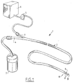
- Fig. 1 shows schematically an embodiment of a drainage catheter according to the invention in the position of use;
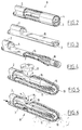
- fig. 2-5 show partly broken away perspective views of the front end of an embodiment of the catheter at different stages of manufacture;
- fig. 6 shows the front end of the catheter in partly broken away perspective view in the position of use.
- Fig. 7 shows the front end of another embodiment of the catheter according to the invention, in a view corresponding to that of fig. 6.
- Fig. 8 shows a cross-section according to line VIII-VIII in fig. 7.
- The
drainage catheter 1 shown in fig. 1 comprises a tube-likebasic body 2 with mutually separatedpressure channel 3 and discharge channel 4. - Connected to the
pressure channel 3 in the situation of use is a source of liquid under pressure, which is indicated in fig. 1 by a pump 5 which feeds liquid from a reservoir 6. - The discharge channel 4 is connected to a discharge reservoir 7 wherein substances discharged with the catheter are stored.
- Formed in a side wall at the
front end 8 of thecatheter 1 is an inlet opening 9 whereby material can be drawn in in a manner to be described later. Thefront end 8 is also provided withnarrow leakage openings - The figures 2-5 show schematically the manner in which the front end of the present embodiment can be manufactured.
- The basic material is shown in fig. 2. As previously described this comprises a tube-like
basic body 2 having therein apressure channel 3 and a discharge channel 4. Thepressure channel 3 has a smaller diameter than the discharge channel 4. The basic material can for example be manufactured by extrusion. From a long piece of extruded basic material a suitable length is removed and at the rear end connecting means for the pressure channel anddischarge channel 3 and 4 respectively are arranged in the usual manner. - The outer wall portion which bounds the discharge channel 4 is ground away from the
front end 8 of the basic material so that a tube-likepressure channel end 15 remains as shown in fig. 3. In this pressure channel end is fixed ajet nozzle 16, for example by glueing or ultrasonic welding. - The
pressure channel end 15 is subsequently bent back and thenozzle 16 inserted into the front end of the discharge channel 4. This situation is likewise fixed by for example glueing or ultrasonic welding. The various material transitions are finished smoothly in the usual manner by grinding. - As is shown in fig. 5, an inlet opening 9 is then formed in the side wall of the
basic body 2, for example by cutting it therein using acutter 17. - During use of the catheter a liquid jet is directed along the inlet opening 9, as indicated in fig. 6 with the
arrow 18 inside the discharge channel 4. Through the ejector action occurring therein there results a suction at the opening 9 whereby liquids, blood clots and small solid particles can be sucked up. This suction is schematically indicated with thearrows 19. - Close to the front end 8 a number of
narrow leakage openings pressure channel 3. These leakage openings allow a small quantity of the liquid fed via thepressure channel 3 to escape. During use of the catheter a contrast fluid is used as liquid so that the liquid escaping via theopenings - The suction working is dependent on the speed and delivery of the
liquid jet 18. When there is danger of the discharge channel becoming blocked a back-pressure occurs in the discharge channel at the position of the inlet opening 9 which immediately reduces the suction action. A self-regulating effect of the suction action is hereby automatically achieved. - The
catheter 25 as shown in fig. 7 also comprises abasic body 26 defining apressure channel 27 and adischarge channel 28. A U-shapedmetal tube 29 is arranged with itslegs pressure channel 27 anddischarge channel 28. The U-tube is fixed in its place by hardenedfilling material 32. The outer end of the catheter is finished by applying a nose portion 33 of soft plastics material. The end portion is in the usual manner ground to a smooth surface. - The
leg 31 of the U-shaped metal tube extending in the discharge channel is provided with a narrowed,tapered portion 34, so that a jet nozzle is formed at the end of theleg 31. Thisjet nozzle 36 directs the fluid which is supplied through the pressure channel in a accurately controlled manner along the inside of the inlet opening 35, so that the desired ejector action is obtained in a reliable and efficient way. - Instead of introducing contrast fluid by means of separate openings as the
openings
Claims (5)
- Drainage catheter (1), comprising a mutually separated pressure channel (3) and a discharge channel (4), formed in one tube like basic body (2), connecting means at a rear end for connecting said pressure channel (3) and said discharge channel (4) to respectively a source (5) of liquid under pressure and discharge means (7) and wherein at the oppositely located front end said discharge channel (4) is connected with an inlet opening (9), formed in a side wall of the catheter (1), said pressure channel (3) bending back at the front end in the direction towards the rear end and forming a jet nozzle (16, 36), arranged in said front end of said discharge channel (4), characterized in that the discharge channel (4) has a continuous cross section from said jet nozzle (16, 36) on towards the rear end, the inlet opening (9) is formed in the side wall of the basic body bounding the discharge channel (4), the jet nozzle (16, 36) is capable of directing a liquid jet along said inlet opening (9) in such a way that at said inlet opening (9) of the catheter sufficient suction is created due to ejector action, without additional suction in the discharge means (7).
- Catheter (1) as claimed in claim 1, wherein in the front end (8) at least one narrow passage opening (10, 11) is formed on a side remote from the inlet opening (9) in an outer wall portion of the basic body (2) bounding the pressure channel (3).
- Catheter (1) as claimed in claim 2, wherein a narrow passage opening (10) is formed in the face of the front end (8) of the catheter (1).
- Drainage catheter as claimed in claim 1 wherein the back bending part of the pressure channel is formed by a metal U-shaped tube (29) sealingly engaging with one leg (30) in said pressure channel and with a second leg (31) in said discharge channel (28).
- Drainage catheter (25) as claimed in claim 4, wherein said second leg (31) of said U-shaped tube (29) is narrowed (34) toward its free end so as to form the jet nozzle (36).
Applications Claiming Priority (2)
| Application Number | Priority Date | Filing Date | Title |
|---|---|---|---|
| NL9000356A NL9000356A (en) | 1990-02-14 | 1990-02-14 | DRAINAGE CATHETER. |
| NL9000356 | 1990-02-14 |
Publications (2)
| Publication Number | Publication Date |
|---|---|
| EP0442579A1 EP0442579A1 (en) | 1991-08-21 |
| EP0442579B1 true EP0442579B1 (en) | 1994-07-20 |
Family
ID=19856595
Family Applications (1)
| Application Number | Title | Priority Date | Filing Date |
|---|---|---|---|
| EP91200292A Expired - Lifetime EP0442579B1 (en) | 1990-02-14 | 1991-02-12 | Drainage catheter |
Country Status (5)
| Country | Link |
|---|---|
| US (3) | US5320599A (en) |
| EP (1) | EP0442579B1 (en) |
| JP (1) | JP3142591B2 (en) |
| DE (2) | DE69102895T4 (en) |
| NL (1) | NL9000356A (en) |
Cited By (4)
| Publication number | Priority date | Publication date | Assignee | Title |
|---|---|---|---|---|
| US6451017B1 (en) | 2000-01-10 | 2002-09-17 | Hydrocision, Inc. | Surgical instruments with integrated electrocautery |
| US6511493B1 (en) | 2000-01-10 | 2003-01-28 | Hydrocision, Inc. | Liquid jet-powered surgical instruments |
| US9295821B2 (en) | 2008-07-02 | 2016-03-29 | Christoph Miethke | Cerebrospinal fluid drainage |
| US9597107B2 (en) | 2002-10-25 | 2017-03-21 | Hydrocision, Inc. | Nozzle assemblies for liquid jet surgical instruments and surgical instruments employing the nozzle assemblies |
Families Citing this family (126)
| Publication number | Priority date | Publication date | Assignee | Title |
|---|---|---|---|---|
| NL9000356A (en) * | 1990-02-14 | 1991-09-02 | Cordis Europ | DRAINAGE CATHETER. |
| DE4126886A1 (en) * | 1991-08-14 | 1993-02-18 | Hp Medica Gmbh | RINSING CATHETER |
| JP2713515B2 (en) * | 1991-09-17 | 1998-02-16 | 禎祐 山内 | Catheter device |
| US5830209A (en) * | 1992-02-05 | 1998-11-03 | Angeion Corporation | Multi-fiber laser catheter |
| NL9300626A (en) * | 1993-04-13 | 1994-11-01 | Cordis Europ | Hydrodynamic suction catheter. |
| US5358473A (en) * | 1993-04-30 | 1994-10-25 | Mitchell Paul G | Apparatus and method for the removal of adherent viscoelastic material |
| SE9302157D0 (en) * | 1993-06-22 | 1993-06-22 | Siemens-Elema Ab | PROCEDURE AND DEVICE CLEANING A CATHETER |
| NL9301181A (en) * | 1993-07-05 | 1995-02-01 | Cordis Europ | A method of manufacturing a catheter with at least one high pressure lumen and catheter. |
| GB9325918D0 (en) * | 1993-12-18 | 1994-02-23 | Smiths Ind Public Ltd | Catheters |
| US5462521A (en) * | 1993-12-21 | 1995-10-31 | Angeion Corporation | Fluid cooled and perfused tip for a catheter |
| US5846219A (en) * | 1994-05-26 | 1998-12-08 | Vancaillie; Thierry G. | Variable backflow suction-hydraulic curet |
| EP0954244A1 (en) * | 1994-07-01 | 1999-11-10 | SciMed Life Systems, Inc. | Intravascular device utilizing fluid to extract occlusive material |
| NL9401184A (en) * | 1994-07-19 | 1996-03-01 | Cordis Europ | Suction catheter. |
| US5571093A (en) * | 1994-09-21 | 1996-11-05 | Cruz; Cosme | Multiple-lumen catheter |
| US5795322A (en) * | 1995-04-10 | 1998-08-18 | Cordis Corporation | Catheter with filter and thrombus-discharge device |
| NL1000105C2 (en) * | 1995-04-10 | 1996-10-11 | Cordis Europ | Catheter with filter and thrombi draining device. |
| US5728123A (en) * | 1995-04-26 | 1998-03-17 | Lemelson; Jerome H. | Balloon actuated catheter |
| US5843022A (en) * | 1995-10-25 | 1998-12-01 | Scimied Life Systems, Inc. | Intravascular device utilizing fluid to extract occlusive material |
| NL1002274C2 (en) * | 1996-02-07 | 1997-08-08 | Cordis Europ | High-frequency thrombectomy catheter. |
| NL1003056C2 (en) * | 1996-05-07 | 1997-11-10 | Cordis Europ | Suction catheter with hemostasis device. |
| NL1003226C2 (en) * | 1996-05-29 | 1997-12-03 | Cordis Europ | Suction catheter with preformed end section. |
| US5800408A (en) * | 1996-11-08 | 1998-09-01 | Micro Therapeutics, Inc. | Infusion device for distributing infusate along an elongated infusion segment |
| US6387087B1 (en) * | 1996-12-11 | 2002-05-14 | Ronald K. Grooters | Aortic cannula |
| US5766194A (en) * | 1996-12-23 | 1998-06-16 | Georgia Skin And Cancer Clinic, Pc | Surgical apparatus for tissue removal |
| US6394996B1 (en) * | 1997-01-07 | 2002-05-28 | C. R. Bard, Inc. | System for aspirating and irrigating tract wounds |
| US6090118A (en) | 1998-07-23 | 2000-07-18 | Mcguckin, Jr.; James F. | Rotational thrombectomy apparatus and method with standing wave |
| US7037316B2 (en) * | 1997-07-24 | 2006-05-02 | Mcguckin Jr James F | Rotational thrombectomy device |
| US6290685B1 (en) | 1998-06-18 | 2001-09-18 | 3M Innovative Properties Company | Microchanneled active fluid transport devices |
| US5876383A (en) * | 1997-09-30 | 1999-03-02 | Grooters; Robert K. | Cannula |
| US6186987B1 (en) | 1997-09-30 | 2001-02-13 | Ronald K. Grooters | Aortic cannula with spoon-shaped lip |
| US6254578B1 (en) | 1997-09-30 | 2001-07-03 | Ronald K. Grooters | Aortic cannula with tapered tip |
| SE511400C2 (en) * | 1997-10-10 | 1999-09-27 | Lundgren Lars Goeran | Containers for collecting liquid and probe with such containers |
| US7879022B2 (en) | 1998-02-06 | 2011-02-01 | Medrad, Inc. | Rapid exchange fluid jet thrombectomy device and method |
| US9586023B2 (en) | 1998-02-06 | 2017-03-07 | Boston Scientific Limited | Direct stream hydrodynamic catheter system |
| WO2009117663A2 (en) * | 2008-03-20 | 2009-09-24 | Medrad, Inc. | Direct stream hydrodynamic catheter system |
| US5989210A (en) | 1998-02-06 | 1999-11-23 | Possis Medical, Inc. | Rheolytic thrombectomy catheter and method of using same |
| US6224570B1 (en) | 1998-02-06 | 2001-05-01 | Possis Medical, Inc. | Rheolytic thrombectomy catheter and method of using same |
| US6458109B1 (en) | 1998-08-07 | 2002-10-01 | Hill-Rom Services, Inc. | Wound treatment apparatus |
| US6186975B1 (en) * | 1998-10-30 | 2001-02-13 | Suzuki Motor Corporation | Liquid conveying catheter |
| US5989271A (en) * | 1998-11-09 | 1999-11-23 | Possis Medical, Inc. | Flexible tip rheolytic thrombectomy catheter and method of constructing same |
| US6375635B1 (en) | 1999-05-18 | 2002-04-23 | Hydrocision, Inc. | Fluid jet surgical instruments |
| US8414543B2 (en) | 1999-10-22 | 2013-04-09 | Rex Medical, L.P. | Rotational thrombectomy wire with blocking device |
| AU2614901A (en) | 1999-10-22 | 2001-04-30 | Boston Scientific Corporation | Double balloon thrombectomy catheter |
| US6824533B2 (en) * | 2000-11-29 | 2004-11-30 | Hill-Rom Services, Inc. | Wound treatment apparatus |
| EP1233808B1 (en) | 1999-11-29 | 2008-07-09 | Hill-Rom Services, Inc. | Wound treatment apparatus |
| US6764462B2 (en) * | 2000-11-29 | 2004-07-20 | Hill-Rom Services Inc. | Wound treatment apparatus |
| US20010043943A1 (en) | 2000-05-22 | 2001-11-22 | Coffey Arthur C. | Combination SIS and vacuum bandage and method |
| DE20009786U1 (en) * | 2000-05-31 | 2000-10-19 | Taufig Ahmmed Ziah | Liposuction device |
| US6855135B2 (en) * | 2000-11-29 | 2005-02-15 | Hill-Rom Services, Inc. | Vacuum therapy and cleansing dressing for wounds |
| US6685681B2 (en) | 2000-11-29 | 2004-02-03 | Hill-Rom Services, Inc. | Vacuum therapy and cleansing dressing for wounds |
| KR20010044407A (en) * | 2001-02-19 | 2001-06-05 | 권병우 | Cannula bars for tissue removal using fluid jet and apparatus adopting the same |
| US6788266B2 (en) * | 2001-04-27 | 2004-09-07 | Tyco Electronics Logistics Ag | Diversity slot antenna |
| CA2446250C (en) * | 2001-05-02 | 2009-07-14 | Axiom Medical Inc. | Transcutaneous fluid drain kit |
| PT1406567E (en) * | 2001-07-12 | 2010-07-21 | Kci Medical Resources | Control of vacuum rate of change |
| US20030069551A1 (en) * | 2001-10-05 | 2003-04-10 | Axiom Medical, Inc. | Multipurpose drain |
| WO2003030966A1 (en) * | 2001-10-11 | 2003-04-17 | Hill-Rom Services, Inc. | Waste container for negative pressure therapy |
| EP1485032B1 (en) | 2001-11-21 | 2007-07-18 | Hydrocision Inc. | Liquid jet surgical instruments incorporating channel openings aligned along the jet beam |
| US6790196B2 (en) * | 2001-12-18 | 2004-09-14 | Scimed Life Systems, Inc. | Aspirating devices for removal of thrombus/lipid from a body lumen |
| EP1461113A4 (en) | 2001-12-26 | 2009-05-06 | Hill Rom Services Inc | Wound vacuum therapy dressing kit |
| ATE387919T1 (en) | 2001-12-26 | 2008-03-15 | Hill Rom Services Inc | VACUUM BAND PACKAGING |
| EP2623138B1 (en) * | 2001-12-26 | 2020-08-05 | KCI Licensing, Inc. | Vented vacuum bandage with irrigation for wound healing and method |
| WO2003073970A1 (en) * | 2002-02-28 | 2003-09-12 | Hill-Rom Services, Inc. | External catheter access to vacuum bandage |
| US8168848B2 (en) * | 2002-04-10 | 2012-05-01 | KCI Medical Resources, Inc. | Access openings in vacuum bandage |
| US7179269B2 (en) * | 2002-05-20 | 2007-02-20 | Scimed Life Systems, Inc. | Apparatus and system for removing an obstruction from a lumen |
| US7896856B2 (en) * | 2002-08-21 | 2011-03-01 | Robert Petrosenko | Wound packing for preventing wound closure |
| US10363061B2 (en) | 2002-10-25 | 2019-07-30 | Hydrocision, Inc. | Nozzle assemblies for liquid jet surgical instruments and surgical instruments for employing the nozzle assemblies |
| US7090654B2 (en) * | 2003-03-28 | 2006-08-15 | Sherwood Services Ag | Catheter with occlusion resistant tip |
| US7141035B2 (en) * | 2003-03-28 | 2006-11-28 | Sherwood Services Ag | Catheter with occlusion resistant tip |
| US7776005B2 (en) * | 2003-03-28 | 2010-08-17 | Covidien Ag | Triple lumen catheter with occlusion resistant tip |
| US7537594B2 (en) * | 2003-05-01 | 2009-05-26 | Covidien Ag | Suction coagulator with dissecting probe |
| US20060129091A1 (en) | 2004-12-10 | 2006-06-15 | Possis Medical, Inc. | Enhanced cross stream mechanical thrombectomy catheter with backloading manifold |
| US7572244B2 (en) | 2004-08-02 | 2009-08-11 | Medrad, Inc. | Miniature cross stream thrombectomy catheter |
| CN101107023B (en) | 2004-11-04 | 2010-06-09 | 科维蒂恩股份公司 | Catheter insertion apparatus |
| US20060271087A1 (en) * | 2005-05-25 | 2006-11-30 | Bowel Management Systems, Llc | Fixed-volume inflation system for balloon catheters |
| US7942864B2 (en) * | 2005-06-10 | 2011-05-17 | Hynes Richard A | Medical device including a catheter providing wound evacuation and medicine dispensing features and related methods |
| US8012117B2 (en) * | 2007-02-06 | 2011-09-06 | Medrad, Inc. | Miniature flexible thrombectomy catheter |
| US20080188793A1 (en) | 2007-02-06 | 2008-08-07 | Possis Medical, Inc. | Miniature flexible thrombectomy catheter |
| US8162878B2 (en) * | 2005-12-05 | 2012-04-24 | Medrad, Inc. | Exhaust-pressure-operated balloon catheter system |
| JP4558693B2 (en) * | 2006-09-04 | 2010-10-06 | コーディス ヨーロッパ エヌ.ブイ. | Suction catheter |
| US9149609B2 (en) * | 2006-10-16 | 2015-10-06 | Embolitech, Llc | Catheter for removal of an organized embolic thrombus |
| US7931651B2 (en) | 2006-11-17 | 2011-04-26 | Wake Lake University Health Sciences | External fixation assembly and method of use |
| US8377016B2 (en) | 2007-01-10 | 2013-02-19 | Wake Forest University Health Sciences | Apparatus and method for wound treatment employing periodic sub-atmospheric pressure |
| KR100899868B1 (en) * | 2007-01-26 | 2009-05-29 | 가톨릭대학교 산학협력단 | Not-occlusive closed suction drain with irrigation function |
| WO2008097993A2 (en) | 2007-02-05 | 2008-08-14 | Boston Scientific Limited | Thrombectomy apparatus and method |
| US9254144B2 (en) | 2007-03-30 | 2016-02-09 | Covidien Lp | Methods and apparatus for thrombectomy system |
| US8974418B2 (en) * | 2007-06-12 | 2015-03-10 | Boston Scientific Limited | Forwardly directed fluid jet crossing catheter |
| US20080319386A1 (en) * | 2007-06-20 | 2008-12-25 | Possis Medical, Inc. | Forwardly directable fluid jet crossing catheter |
| US9402973B2 (en) * | 2007-07-06 | 2016-08-02 | Vital 5, Llc | Constrained fluid delivery device |
| ES2661762T3 (en) | 2007-10-10 | 2018-04-03 | Wake Forest University Health Sciences | Devices to treat spinal cord tissue |
| US20130096518A1 (en) | 2007-12-06 | 2013-04-18 | Smith & Nephew Plc | Wound filling apparatuses and methods |
| US11253399B2 (en) | 2007-12-06 | 2022-02-22 | Smith & Nephew Plc | Wound filling apparatuses and methods |
| WO2009079539A1 (en) * | 2007-12-17 | 2009-06-25 | Medrad, Inc. | Rheolytic thrombectomy catheter with self-inflation distal balloon |
| US8439878B2 (en) | 2007-12-26 | 2013-05-14 | Medrad, Inc. | Rheolytic thrombectomy catheter with self-inflating proximal balloon with drug infusion capabilities |
| WO2009089435A1 (en) | 2008-01-09 | 2009-07-16 | Wake Forest University Health Sciences | Device and method for treating central nervous system pathology |
| CN104771197A (en) | 2008-07-18 | 2015-07-15 | 韦克福里斯特大学健康科学院 | Apparatus and method for cardiac tissue modulation by topical application of vacuum to minimize cell death and damage |
| US9510854B2 (en) * | 2008-10-13 | 2016-12-06 | Boston Scientific Scimed, Inc. | Thrombectomy catheter with control box having pressure/vacuum valve for synchronous aspiration and fluid irrigation |
| US20090192448A1 (en) * | 2009-01-28 | 2009-07-30 | Talamonti Anthony R | Oral gastric lavage apparatus |
| CN103949001B (en) * | 2009-06-26 | 2016-08-24 | 泰科保健集团有限合伙公司 | Catheter insertion system |
| CA2715857A1 (en) | 2009-09-30 | 2011-03-30 | Tyco Healthcare Group Lp | Medical catheter having a design providing low recirculation and reversibility |
| US9265913B2 (en) | 2010-09-22 | 2016-02-23 | Vital 5, Llc | Catheter assembly |
| US8591450B2 (en) | 2010-06-07 | 2013-11-26 | Rex Medical L.P. | Dialysis catheter |
| US9446224B2 (en) | 2010-09-22 | 2016-09-20 | Vital 5, L.L.C. | Barrier catheter |
| JP2012065861A (en) | 2010-09-24 | 2012-04-05 | Nihon Covidien Kk | Dialysis catheter |
| USD679804S1 (en) | 2011-09-22 | 2013-04-09 | Vital 5, Llc | Catheter |
| US8747343B2 (en) | 2011-09-30 | 2014-06-10 | Covidien Lp | Hemodialysis catheter with improved side opening design |
| US9072867B2 (en) | 2011-09-30 | 2015-07-07 | Covidien Lp | Catheter with external flow channel |
| US9238122B2 (en) | 2012-01-26 | 2016-01-19 | Covidien Lp | Thrombectomy catheter systems |
| CN102553058B (en) * | 2012-02-28 | 2016-06-08 | 解启莲 | Reverse arterial intubation tube |
| US9155862B2 (en) | 2012-09-28 | 2015-10-13 | Covidien Lp | Symmetrical tip acute catheter |
| US9615842B2 (en) * | 2014-03-21 | 2017-04-11 | Terumo Kabushiki Kaisha | Calculus retrieving/removing device and method |
| US9433427B2 (en) | 2014-04-08 | 2016-09-06 | Incuvate, Llc | Systems and methods for management of thrombosis |
| US9248221B2 (en) | 2014-04-08 | 2016-02-02 | Incuvate, Llc | Aspiration monitoring system and method |
| US9883877B2 (en) | 2014-05-19 | 2018-02-06 | Walk Vascular, Llc | Systems and methods for removal of blood and thrombotic material |
| US10583228B2 (en) | 2015-07-28 | 2020-03-10 | J&M Shuler Medical, Inc. | Sub-atmospheric wound therapy systems and methods |
| US10702292B2 (en) | 2015-08-28 | 2020-07-07 | Incuvate, Llc | Aspiration monitoring system and method |
| US10561440B2 (en) | 2015-09-03 | 2020-02-18 | Vesatek, Llc | Systems and methods for manipulating medical devices |
| US20170100142A1 (en) | 2015-10-09 | 2017-04-13 | Incuvate, Llc | Systems and methods for management of thrombosis |
| US10226263B2 (en) | 2015-12-23 | 2019-03-12 | Incuvate, Llc | Aspiration monitoring system and method |
| US20170215897A1 (en) * | 2016-01-28 | 2017-08-03 | Gyrus Acmi, Inc., D.B.A. Olympus Surgical Technologies America | Apparatus for Stone Fragments Removal |
| US10492805B2 (en) | 2016-04-06 | 2019-12-03 | Walk Vascular, Llc | Systems and methods for thrombolysis and delivery of an agent |
| CN106267398B (en) * | 2016-08-29 | 2018-11-20 | 安徽通灵仿生科技有限公司 | A kind of auxiliary circulation two-way arterial duct, control system and its control method |
| US11786620B2 (en) | 2018-04-30 | 2023-10-17 | CathBuddy, Inc. | Handheld cleaner-disinfector for medical devices |
| US10639389B2 (en) | 2018-04-30 | 2020-05-05 | CathBuddy, Inc | Methods and devices for portable sterilization and containment of medical devices |
| US11678905B2 (en) | 2018-07-19 | 2023-06-20 | Walk Vascular, Llc | Systems and methods for removal of blood and thrombotic material |
| CN109157730A (en) * | 2018-08-29 | 2019-01-08 | 江苏省人民医院(南京医科大学第附属医院) | Catheter capable of being pressurized |
| US11160917B2 (en) | 2020-01-22 | 2021-11-02 | J&M Shuler Medical Inc. | Negative pressure wound therapy barrier |
Family Cites Families (40)
| Publication number | Priority date | Publication date | Assignee | Title |
|---|---|---|---|---|
| US1902418A (en) * | 1931-11-02 | 1933-03-21 | Jensen Salsbery Lab Inc | Surgical instrument |
| US2147652A (en) * | 1935-07-27 | 1939-02-21 | Rodney S Kennison | Nozzle |
| US2804075A (en) * | 1955-11-14 | 1957-08-27 | Ruth O Borden | Non-clogging surgical aspirator |
| US3429313A (en) * | 1966-02-01 | 1969-02-25 | Ram Domestic Products Co | Medical drainage pump |
| US3636940A (en) * | 1967-12-07 | 1972-01-25 | Leland C Gravlee | Method for collecting cellular material by circulating a fluid within a body cavity |
| US3542031A (en) * | 1968-06-24 | 1970-11-24 | Marshall B Taylor | Vacuum curette |
| US3955573A (en) * | 1974-10-11 | 1976-05-11 | Sorenson Research Co., Inc. | Anticoagulant delivery device and method |
| US4014333A (en) * | 1975-09-22 | 1977-03-29 | Mcintyre David J | Instrument for aspirating and irrigating during ophthalmic surgery |
| US4294251A (en) * | 1978-10-17 | 1981-10-13 | Greenwald A Seth | Method of suction lavage |
| US4227533A (en) * | 1978-11-03 | 1980-10-14 | Bristol-Myers Company | Flushable urinary catheter |
| DE3019115C2 (en) * | 1980-05-20 | 1982-10-28 | Aesculap-Werke Ag Vormals Jetter & Scheerer, 7200 Tuttlingen | Instrument for loosening a blood clot |
| DE3235974A1 (en) * | 1981-11-24 | 1983-06-01 | Volkmar Dipl.-Ing. Merkel (FH), 8520 Erlangen | DEVICE FOR REMOVAL OR FOR THE EXPANSION OF CONSTRAINTS IN BODY LIQUID LEADING VESSELS |
| US4445892A (en) * | 1982-05-06 | 1984-05-01 | Laserscope, Inc. | Dual balloon catheter device |
| US4468216A (en) * | 1982-05-20 | 1984-08-28 | Rudolph Muto | Irrigation suction catheter |
| DE3421390C2 (en) * | 1984-06-08 | 1986-07-17 | Werner Dr.med. 4330 Mülheim Schubert | High pressure catheter with cutting and / or abrasion device |
| DE8426270U1 (en) * | 1984-09-06 | 1985-02-14 | Veltrup, Elmar Michael, Dipl.-Ing., 4150 Krefeld | DEVICE FOR REMOVING SOLID BODIES OR DEPOSITS FROM BODY VESSELS |
| US4642092A (en) * | 1984-12-10 | 1987-02-10 | Gerald Moss | Gastrointestinal aspirating device with suction breakers |
| US4715848A (en) * | 1985-04-15 | 1987-12-29 | Beroza Gregory A | Gastro-intestinal lavage system and method |
| SE448608B (en) * | 1985-07-15 | 1987-03-09 | Leif Nilsson | CATHETER |
| US5135482A (en) * | 1985-12-31 | 1992-08-04 | Arnold Neracher | Hydrodynamic device for the elimination of an organic deposit obstructing a vessel of a human body |
| CA1281968C (en) * | 1985-12-31 | 1991-03-26 | Arnold Neracher | Hydrodynamic device for removing an organic deposit obstructing a vessel in the human body |
| US4735620A (en) * | 1986-01-16 | 1988-04-05 | Ruiz Oscar F | Non-whip catheter |
| US4846814A (en) * | 1986-01-16 | 1989-07-11 | Sherwood Medical Company | Non-whip catheter |
| US4772260A (en) * | 1986-05-02 | 1988-09-20 | Heyden Eugene L | Rectal catheter |
| US4729763A (en) * | 1986-06-06 | 1988-03-08 | Henrie Rodney A | Catheter for removing occlusive material |
| US4747821A (en) * | 1986-10-22 | 1988-05-31 | Intravascular Surgical Instruments, Inc. | Catheter with high speed moving working head |
| US4749376A (en) * | 1986-10-24 | 1988-06-07 | Intravascular Surgical Instruments, Inc. | Reciprocating working head catheter |
| US4757821A (en) * | 1986-11-12 | 1988-07-19 | Corazonix Corporation | Omnidirectional ultrasonic probe |
| US4795438A (en) * | 1987-05-13 | 1989-01-03 | Intravascular Surgical Instruments, Inc. | Method and apparatus for forming a restriction in a vessel, duct or lumen |
| US4861333A (en) * | 1987-10-13 | 1989-08-29 | Meador Lawrence D | Animal aspirating and irrigating apparatus |
| JPH01198539A (en) * | 1987-10-26 | 1989-08-10 | Marui Ika:Kk | Water jet knife apparatus for cerebral surgery use |
| IT212331Z2 (en) * | 1987-11-27 | 1989-07-04 | Lorenzo Molinari | EQUIPMENT FOR ADJUSTABLE REMOVAL OF SURFACE PORTIONS OF HUMAN FABRIC |
| US4961731A (en) * | 1988-06-09 | 1990-10-09 | Sherwood Medical Company | Angiographic catheter with balanced dye injection openings |
| US4950238A (en) * | 1988-07-07 | 1990-08-21 | Clarence E. Sikes | Hydro-rotary vascular catheter |
| SE462414B (en) * | 1988-11-15 | 1990-06-25 | Paal Svedman | INSTRUMENTS FOR WEAVING OF WEAVEN |
| US4968307A (en) * | 1989-01-09 | 1990-11-06 | Advanced Cardiovascular Systems, Inc. | Catheter for uniform distribution of therapeutic fluids |
| JPH0751062Y2 (en) * | 1989-01-13 | 1995-11-22 | 晴夫 高瀬 | Suction tube for removing biological tissue |
| NL9000356A (en) * | 1990-02-14 | 1991-09-02 | Cordis Europ | DRAINAGE CATHETER. |
| US5135484A (en) * | 1990-05-09 | 1992-08-04 | Pioneering Technologies, Inc. | Method of removing plaque from vessels |
| US5496267A (en) * | 1990-11-08 | 1996-03-05 | Possis Medical, Inc. | Asymmetric water jet atherectomy |
-
1990
- 1990-02-14 NL NL9000356A patent/NL9000356A/en not_active Application Discontinuation
-
1991
- 1991-01-31 JP JP03010783A patent/JP3142591B2/en not_active Expired - Lifetime
- 1991-02-12 DE DE69102895T patent/DE69102895T4/en not_active Expired - Lifetime
- 1991-02-12 DE DE69102895A patent/DE69102895D1/en not_active Expired - Lifetime
- 1991-02-12 EP EP91200292A patent/EP0442579B1/en not_active Expired - Lifetime
-
1992
- 1992-06-09 US US07/894,174 patent/US5320599A/en not_active Expired - Lifetime
-
1994
- 1994-01-18 US US08/182,717 patent/US5395315A/en not_active Expired - Lifetime
-
1996
- 1996-11-04 US US08/743,324 patent/US5785678A/en not_active Expired - Lifetime
Cited By (5)
| Publication number | Priority date | Publication date | Assignee | Title |
|---|---|---|---|---|
| US6451017B1 (en) | 2000-01-10 | 2002-09-17 | Hydrocision, Inc. | Surgical instruments with integrated electrocautery |
| US6511493B1 (en) | 2000-01-10 | 2003-01-28 | Hydrocision, Inc. | Liquid jet-powered surgical instruments |
| US6669710B2 (en) | 2000-01-10 | 2003-12-30 | Hydrocision, Inc. | Liquid jet-powered surgical instruments |
| US9597107B2 (en) | 2002-10-25 | 2017-03-21 | Hydrocision, Inc. | Nozzle assemblies for liquid jet surgical instruments and surgical instruments employing the nozzle assemblies |
| US9295821B2 (en) | 2008-07-02 | 2016-03-29 | Christoph Miethke | Cerebrospinal fluid drainage |
Also Published As
| Publication number | Publication date |
|---|---|
| JPH0751358A (en) | 1995-02-28 |
| DE69102895D1 (en) | 1994-08-25 |
| US5395315A (en) | 1995-03-07 |
| DE69102895T4 (en) | 1995-08-10 |
| US5320599A (en) | 1994-06-14 |
| EP0442579A1 (en) | 1991-08-21 |
| NL9000356A (en) | 1991-09-02 |
| DE69102895T2 (en) | 1994-11-03 |
| JP3142591B2 (en) | 2001-03-07 |
| US5785678A (en) | 1998-07-28 |
Similar Documents
| Publication | Publication Date | Title |
|---|---|---|
| EP0442579B1 (en) | Drainage catheter | |
| US6001078A (en) | Selective positioning drainage catheter | |
| EP0620016B1 (en) | Hydrodynamic suction catheter | |
| US5908403A (en) | Drainage catheter with hemostatic device | |
| JP2713515B2 (en) | Catheter device | |
| CA2160408C (en) | Suction catheter | |
| US7494485B2 (en) | Fluidic interventional device and method of distal protection | |
| US4898574A (en) | Lithotomic apparatus | |
| AU583989B2 (en) | Ophthalmic aspirating/irrigating device | |
| EP0147192A2 (en) | Recanalisation catheter with cutter head | |
| US5785675A (en) | Thrombectomy device | |
| US6676637B1 (en) | Single operator exchange fluid jet thrombectomy method | |
| US6719718B2 (en) | Thrombectomy catheter and system | |
| JPH0741042B2 (en) | Lavage catheter | |
| EP0558846B1 (en) | Suction tube for use in surgical operation | |
| US5584314A (en) | Self-cleaning inlet head for a fluid | |
| JPH07509377A (en) | dental air polishing system | |
| JP2001507971A (en) | Device for suction and irrigation of tubular wounds | |
| WO2002026289A1 (en) | Catheter system | |
| JP7312262B2 (en) | catheter device | |
| JP2017184845A (en) | Medical suction tube and liquid injection device | |
| JPH0330369B2 (en) |
Legal Events
| Date | Code | Title | Description |
|---|---|---|---|
| PUAI | Public reference made under article 153(3) epc to a published international application that has entered the european phase |
Free format text: ORIGINAL CODE: 0009012 |
|
| AK | Designated contracting states |
Kind code of ref document: A1 Designated state(s): DE FR GB NL |
|
| 17P | Request for examination filed |
Effective date: 19920219 |
|
| 17Q | First examination report despatched |
Effective date: 19920629 |
|
| GRAA | (expected) grant |
Free format text: ORIGINAL CODE: 0009210 |
|
| AK | Designated contracting states |
Kind code of ref document: B1 Designated state(s): DE FR GB NL |
|
| REF | Corresponds to: |
Ref document number: 69102895 Country of ref document: DE Date of ref document: 19940825 |
|
| ET | Fr: translation filed | ||
| PLBE | No opposition filed within time limit |
Free format text: ORIGINAL CODE: 0009261 |
|
| STAA | Information on the status of an ep patent application or granted ep patent |
Free format text: STATUS: NO OPPOSITION FILED WITHIN TIME LIMIT |
|
| 26N | No opposition filed | ||
| REG | Reference to a national code |
Ref country code: GB Ref legal event code: IF02 |
|
| PGFP | Annual fee paid to national office [announced via postgrant information from national office to epo] |
Ref country code: FR Payment date: 20100223 Year of fee payment: 20 |
|
| PGFP | Annual fee paid to national office [announced via postgrant information from national office to epo] |
Ref country code: GB Payment date: 20100202 Year of fee payment: 20 Ref country code: DE Payment date: 20100219 Year of fee payment: 20 |
|
| PGFP | Annual fee paid to national office [announced via postgrant information from national office to epo] |
Ref country code: NL Payment date: 20100209 Year of fee payment: 20 |
|
| REG | Reference to a national code |
Ref country code: DE Ref legal event code: R071 Ref document number: 69102895 Country of ref document: DE |
|
| REG | Reference to a national code |
Ref country code: NL Ref legal event code: V4 Effective date: 20110212 |
|
| REG | Reference to a national code |
Ref country code: GB Ref legal event code: PE20 Expiry date: 20110211 |
|
| PG25 | Lapsed in a contracting state [announced via postgrant information from national office to epo] |
Ref country code: NL Free format text: LAPSE BECAUSE OF EXPIRATION OF PROTECTION Effective date: 20110212 |
|
| PG25 | Lapsed in a contracting state [announced via postgrant information from national office to epo] |
Ref country code: GB Free format text: LAPSE BECAUSE OF EXPIRATION OF PROTECTION Effective date: 20110211 |
|
| PG25 | Lapsed in a contracting state [announced via postgrant information from national office to epo] |
Ref country code: DE Free format text: LAPSE BECAUSE OF EXPIRATION OF PROTECTION Effective date: 20110212 |