EP0382319A2 - Method and apparatus for piercing brittle materials with high velocity abrasive-laden waterjets - Google Patents
Method and apparatus for piercing brittle materials with high velocity abrasive-laden waterjets Download PDFInfo
- Publication number
- EP0382319A2 EP0382319A2 EP19900200301 EP90200301A EP0382319A2 EP 0382319 A2 EP0382319 A2 EP 0382319A2 EP 19900200301 EP19900200301 EP 19900200301 EP 90200301 A EP90200301 A EP 90200301A EP 0382319 A2 EP0382319 A2 EP 0382319A2
- Authority
- EP
- European Patent Office
- Prior art keywords
- jet
- abrasive
- orifice
- region
- nozzle assembly
- Prior art date
- Legal status (The legal status is an assumption and is not a legal conclusion. Google has not performed a legal analysis and makes no representation as to the accuracy of the status listed.)
- Withdrawn
Links
Images

Classifications
-
- B—PERFORMING OPERATIONS; TRANSPORTING
- B24—GRINDING; POLISHING
- B24C—ABRASIVE OR RELATED BLASTING WITH PARTICULATE MATERIAL
- B24C5/00—Devices or accessories for generating abrasive blasts
- B24C5/02—Blast guns, e.g. for generating high velocity abrasive fluid jets for cutting materials
-
- B—PERFORMING OPERATIONS; TRANSPORTING
- B24—GRINDING; POLISHING
- B24C—ABRASIVE OR RELATED BLASTING WITH PARTICULATE MATERIAL
- B24C1/00—Methods for use of abrasive blasting for producing particular effects; Use of auxiliary equipment in connection with such methods
- B24C1/04—Methods for use of abrasive blasting for producing particular effects; Use of auxiliary equipment in connection with such methods for treating only selected parts of a surface, e.g. for carving stone or glass
- B24C1/045—Methods for use of abrasive blasting for producing particular effects; Use of auxiliary equipment in connection with such methods for treating only selected parts of a surface, e.g. for carving stone or glass for cutting
-
- B—PERFORMING OPERATIONS; TRANSPORTING
- B24—GRINDING; POLISHING
- B24C—ABRASIVE OR RELATED BLASTING WITH PARTICULATE MATERIAL
- B24C5/00—Devices or accessories for generating abrasive blasts
- B24C5/02—Blast guns, e.g. for generating high velocity abrasive fluid jets for cutting materials
- B24C5/04—Nozzles therefor
-
- B—PERFORMING OPERATIONS; TRANSPORTING
- B24—GRINDING; POLISHING
- B24C—ABRASIVE OR RELATED BLASTING WITH PARTICULATE MATERIAL
- B24C7/00—Equipment for feeding abrasive material; Controlling the flowability, constitution, or other physical characteristics of abrasive blasts
- B24C7/0046—Equipment for feeding abrasive material; Controlling the flowability, constitution, or other physical characteristics of abrasive blasts the abrasive material being fed in a gaseous carrier
- B24C7/0076—Equipment for feeding abrasive material; Controlling the flowability, constitution, or other physical characteristics of abrasive blasts the abrasive material being fed in a gaseous carrier the blasting medium being a liquid stream
-
- Y—GENERAL TAGGING OF NEW TECHNOLOGICAL DEVELOPMENTS; GENERAL TAGGING OF CROSS-SECTIONAL TECHNOLOGIES SPANNING OVER SEVERAL SECTIONS OF THE IPC; TECHNICAL SUBJECTS COVERED BY FORMER USPC CROSS-REFERENCE ART COLLECTIONS [XRACs] AND DIGESTS
- Y10—TECHNICAL SUBJECTS COVERED BY FORMER USPC
- Y10T—TECHNICAL SUBJECTS COVERED BY FORMER US CLASSIFICATION
- Y10T83/00—Cutting
- Y10T83/04—Processes
- Y10T83/0591—Cutting by direct application of fluent pressure to work
Definitions
- a high velocity waterjet is first formed by compressing the liquid to an operating pressure of 35,000 to 70,000 psi, and forcing the compressed liquid through an orifice having a diameter approximating that of a human hair; namely, 0.001-0.015 inches.
- the resulting highly coherent jet is discharged from the orifice at a velocity which approaches or exceeds the speed of sound.
- the liquid most frequently used to form the jet is water, and the high velocity jet described hereinafter may accordingly be identified as a waterjet.
- the jet as comprising water should not be interpreted as a limitation.
- the high velocity jet thus formed is passed through a mixing region, which is typically within the same housing as the aforedescribed components.
- a quantity of abrasive is entrained into the jet in the mixing region by the low pressure region which surrounds the flowing liquid in accordance with the Bernoulli Principle.
- the abrasive is typically (but not limited to) a fine silica or garnet, and is coupled into the mixing region from a hopper which is external to the nozzle housing.
- abrasive-laden waterjet is discharged against a workpiece which is supported closely adjacent to the discharge end of the nozzle housing. Additional information and details concerning abrasivejet technology may be found in my U.S. Patent 4,648,215, the contents of which are hereby incorporated by reference.
- the term "abrasivejet” is used herein as a shorthand expression for "abrasive-laden waterjet” in accordance with standard terminology in the art.
- An abrasivejet cutting system which drills and cuts brittle material, without destruction of the workpiece.
- the system includes a cutting nozzle housing having a fluid-conducting, generally axially-extending passage extending from an upstream end region to a downstream end region.
- the housing has an inlet port communicating with the upstream end region for permitting the ingress of high pressure liquid into the passage.
- Orifice-defining means positioned in the downstream end region of the passageway produces a highly coherent, high velocity cutting jet from the high pressure fluid passing through the orifice.
- Means are included in the assembly for conducting abrasive particles from an external abrasive source to a mixing region within the housing which is adjacent to the high velocity jet so that the abrasive becomes entrained with the jet by the low pressure region which surrounds the moving liquid.
- means are included for discharging the abrasive-laden jet from the downstream end of the housing.
- the system includes means for reducing the impact stress of the abrasivejet on the workpiece until at least the top surface of the workpiece has been pierced.
- the impact stress is reduced by a reduction in the pressure of the jet-forming liquid prior to formation of the jet.
- a pressure-reducing orifice is placed in the supply line to the cutting jet, together with a bypass valve that selectively decouples the pressure-reducing orifice from the supply line.
- the high-pressure, jet-forming liquid is forced through the pressure-reducing orifice during the workpiece-piercing (i.e., drilling) phase of operation, and bypasses the orifice during the normal cutting phase.
- the impact stress is reduced by means which degrade the coherency of the jet during the workpiece-piercing phase.
- the coherency of the jet is degraded by means which creates turbulence in the jet-forming liquid upstream or downstream of the jet-forming orifice.
- the coherency of the waterjet is restored after the workpiece has been pierced by the abrasivejet.
- the system disclosed herein includes auxiliary means for compelling abrasive through the mixing region in the nozzle housing during the drilling phase so that a generally consistent feed rate is maintained independent of the cutting jet's characteristics.
- the cutting nozzle assembly includes an auxiliary conduit which communicates with the mixing region.
- a source of partial vacuum is operatively coupled to the auxiliary conduit during the drilling phase, and draws abrasive from the external abrasive source through the mixing region and out the auxiliary conduit.
- the partial vacuum source is an auxiliary waterjet nozzle assembly coupled to the cutting nozzle assembly in a manner which enables the auxiliary jet to pull abrasive through the mixing region of the cutting nozzle assembly. Since the auxiliary jet is not discharged against a workpiece, and performs no cutting or drilling, the components and dimensions of the auxiliary assembly may be sized for optimum siphoning characteristics.
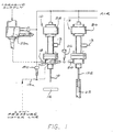
- FIG. 1 is a schematic illustration of an abrasivejet nozzle arrangement constructed in accordance with the invention.
- a pair of abrasivejet nozzle assemblies 10, 12 are depicted, each of which is coupled to a source of high pressure water via a respective inlet port 13.
- the term "high pressure” is used to denote pressures in the range of 35,000 to 55,000 psi.
- sources of such highly pressurized water are typically intensifier pumps which form part of an abrasivejet cutting system. A description of these pumps is beyond the scope of this specification, and is accordingly omitted for the sake of brevity.
- the nozzle assembly 10 is mounted for movement with respect to a workpiece 14 in any manner known in the art. Typically, an X-Y carriage is employed for such purposes, and the movement is controlled by a microprocessor.
- the nozzle assembly 10 includes a discharge tube 16 from which an abrasive-laden, highly coherent, high velocity jet of liquid exits the assembly. The downstream end of the tube 16 is positioned closely adjacent the workpiece during the cutting operation. In practice a set-off distance of 0.10 inches is satisfactory.
- Abrasive particles are conducted into the cutting nozzle assembly 10 from an external hopper, or other source, through an abrasive-conducting inlet 18.
- the abrasive typically comprises (but is not limited to) a fine garnet or silica powder, and is drawn into the assembly by the low pressure surrounding the moving jet in accordance with the Bernoulli Principle. Additional details concerning the formation of abrasive jets are set forth in U.S. Patent 4,648,215 which issued on March 10, 1987 to Hashish, et. al. The contents of that patent are incorporated by reference. Additional details concerning the preferred components of the cutting nozzle assembly 10 are discussed below with respect to Figure 2A.
- the cutting nozzle assembly 10 further includes a fluid inlet 70 which, as also described in greater detail below, permits the ingress of a jet-degrading fluid into an internal mixing region 58 ( Figure 2A) where the abrasive is introduced into the cutting jet.
- the fluid inlet 70 communicates with a source of liquid via a conduit 19a such that a flow of water up to 10 gpm and pressure up to 100 psi can be introduced into the chamber which contains the mixing region.
- a length of Tygon tubing having a 0.15-inch I.D. and a 3 ft. length coupled to an ordinary 60 lb/in2 water line of the type supplying normal drinking water has been found satisfactory.
- the second nozzle assembly 12 is utilized as a partial vacuum source to maintain a substantially constant flow rate of jet-degrading fluid and abrasive through the cutting nozzle assembly 10.
- the vacuum nozzle assembly 12 which may conveniently be mounted for ganged movement with the cutting nozzle assembly 10, accordingly includes an abrasive-conducting inlet 20 communicating via a conduit 24 with an abrasive-conducting output 22 formed in the nozzle assembly 10.
- the conduit 24, conveniently formed from the same material as the line which couples the abrasive source to the cutting nozzle assembly 10, passes through a valving arrangement 26.
- the valving arrangement 26 is a solenoid operated air-driven pinch valve operable by a standard 100 psi source commonly found in industrial environments.
- the vacuum nozzle assembly 12 has a jet-discharging tube 122 comparable to the discharge tube 16 of the cutting nozzle assembly 10.
- the discharge tube 122 is positioned with its jet-discharging end in an energy-dissipating device 25, commonly referred to in the art as a catcher. Since the vacuum nozzle assembly 12 is not intended to cut a workpiece, its components are sized to create maximum suction, rather than an efficient cutting jet. As will be evident, a vacuum from conventional sources of the type found in typical shop environments may be utilized instead of the vacuum nozzle.
- valve means 28, 30 are air-driven valve structures operable from the same air supply as the abrasive valve 27.
- suitable valve structures may be found in U.S. Patent 4,313,570 which issued on February 2, 1982 to John H. Olsen. The contents of that patent are incorporated by reference.
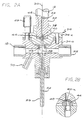
- FIG 2A is a sectional view of the cutting nozzle assembly 10, which comprises a waterjet orifice housing 32 and an abrasivejet housing 34.
- the waterjet orifice housing 32 has an axially-extending passage 33 extending from an upstream end region 36 to a downstream end region 38. Typically, the passage is approximately 0.25 inches in diameter.
- the inlet port 13 Figure 1) of the assembly communicates with the upstream end region 36 to permit the ingress of high pressure water into the passage 33.
- a jewel orifice-defining member 40 shown more clearly in magnification in Figure 2B, has an orifice 40a and is positioned in the downstream end region 38 of the passage 33 to produce a highly coherent, high velocity cutting jet 42 from the high pressure water passing through the orifice 40a.
- the jewel orifice member 40 is preferably formed from an extremely hard material such as synthetic sapphire or ruby having a 0.003 to 0.070 inch diameter jet-forming orifice 40a.
- the jewel 40 is mounted on a jewel holder 44 within the passage 33.
- the abrasivejet body 34 comprises upper and lower body members 34a, 34b which are secured together by three screws 46.
- the upper body member 34a is preferably secured to the waterjet housing 15 by internally threaded, cylindrical cavity 48 which threads onto external threads circumventing the downstream end of the waterjet housing 15.
- the abutting faces of the upper and lower body members are shaped to form a "ball and socket" arrangement which enables the axially-extending passageway 52 of a discharge tube 56 in the lower member to be axially aligned with the jet-forming orifice 40a by means of the selective rotation of the adjustment screws 46. Additional details concerning the alignment mechanism may be found in co-pending U.S. Serial number 794,234, filed October 31, 1985 which is assigned to the present assignee. The contents of this patent application are incorporated by reference.
- the lower body member further includes an abrasive-conducting entry port 18 for conducting abrasive from an external hopper (or other source) to a mixing region 58 within the lower body member.
- abrasive are conducted to a mixing region downstream from the jet-producing orifice 40a and adjacent the high velocity jet so that the abrasive becomes entrained with the jet by the low pressure region which surrounds the moving liquid in accordance with the Bernoulli Effect.
- An outlet port 22 for conducting abrasive-laden liquid is formed in the lower body member 34b.
- the outlet port 22, which communicates with the mixing region, is preferably diametrically opposite to, and co-axially aligned with, the inlet port 18.
- the discharge tube 56 is positioned in an axially-extending bore formed within the lower body member 34b.
- the tube 56 is formed from tungsten carbide, or other extremely hard material, and has an internal diameter of from 0.010 to 0.20 inches.
- the downstream end of the discharge tube 56 discharges the abrasive-laden jet against the workpiece 14 ( Figure 1).
- the nozzle assembly includes means for degrading the coherency of the waterjet until at least the top surface of the workpiece has been pierced.
- Figure 3 is an enlarged fragmentary view of the waterjet nozzle portion of the nozzle assembly in Figure 2A, and illustrates one embodiment which selectively degrades the waterjet's coherency.
- the waterjet nozzle portion is shown to include a tubular near-jewel insert 62 formed from a non-corroding metal such as stainless steel or brass.
- the insert 62 is generally co-axially positioned over the jet-forming orifice 40a to receive the downstream end of an elongated stem 60 that extends axially through the passageway 33 of the waterjet body.
- the outer diameter of the stem is approximately 0.040 inches.
- the inner diameter of the insert 62 is from 0.002 to 0.030 inches greater than the outer diameter of the stem 60, and has an axial length of from approximately 0.1 to 0.5 inches.
- the stem 60 serves to block the flow of fluid into the orifice when it is lowered into contact with the face of the orifice-defining jewel element 40.
- the stem 60 is movable axially between a first position in which its downstream end is surrounded by the insert, to a second position in which its downstream end is approximately 0.25 inches above the insert.
- the stem's downstream end cooperates with the inner diameter of the insert to impart a generally annular cross-section to the flow of water into the orifice, degrading the coherency of the jet formed by the orifice.
- the downstream end of the stem is withdrawn to a position approximately 0.25 inches above the top of the insert, the stem is sufficiently displaced from the upstream face of the orifice to avoid degradation of the jet's coherency.
- the insert may be moved from the downstream end by magnetically responsive material so that its movement can be conveniently induced by magnetic means external to the housing. Naturally, hydraulics and pneumatics may be used instead of magnetics to provide the desired movement.
- the stem may be provided with a radially enlarged portion 64 at its upstream end to degrade the jet's coherency.
- the outer diameter of the radially enlarged portion 64 of the stem is approximately 0.001 to 0.040 inches less than the inside diameter of the bore 33, and is positioned to partially impede the entry of high pressure fluid through the inlet port 18 when the stem is lifted off the jewel orifice member to permit fluid flow through the orifice.
- the enlarged segment 64 accordingly creates a degree of turbulence in the incoming high pressure fluid which degrades the coherency of the jet.
- a stem having the aforedescribed radially enlarged portion can be used with or without an insert 62. When utilized with the insert, the turbulence that it creates supplements the degradation in coherency created by the forced annular flow of the water into the orifice as the water passes around the downstream end of the stem and through the insert 64.
- the inlet port 18 is approximately 2 to 4 inches from the upstream face of the jet-forming orifice and has a diameter of approximately 0.187 inches. Accordingly, the radially enlarged portion of the stem can be 0.187 inches in length.
- the enlarged section 64 When the stem is moved 0.187 inches away from the jewel orifice member, the enlarged section 64 is in a non-interfering position with respect to the entering water, and the resulting generally laminar flow of water upstream of the jet-defining orifice results in the production of a coherent jet.
- the jet is weakened to a greater degree with high water flow rates and as the position of the enlarged portion is moved downstream.
- the enlarged portion should be 2 to 3 inches above the orifice; for smaller jets of 0.003 inches to 0.010 inches, the enlarged portion should be 0.25 to 1.0 inches from the jewel orifice.
- the jet-weakening turbulence is induced during the initial piercing of the workpiece's top surface by the abrasivejet.
- the illustrated means for accomplishing these functions are a suction-inducing nozzle assembly 12 ( Figure 1), and an abrasive-conducting discharge port 22 communicating with the mixing region 58 for use in coupling the mixing region to the mixing region of the suction nozzle assembly.
- the non-entrained abrasive particles exit from the cutting nozzle assembly 10 via a path which is not directed at the workpiece.
- the suction nozzle assembly 12 contains components which are similar to that of the cutting nozzle assembly illustrated in Figure 2A, except for the absence of an abrasive-conducting discharge port analogous to port 22 and a fluid inlet 70. Additionally, various components of the suction nozzle assembly 12 are sized for maximum suction of the abrasive, rather than for optimal cutting efficiency.
- the cutting nozzle assembly 10 includes a jet-forming orifice having a diameter in the range of 0.005 to 0.025 inches, and a discharge tube having a diameter in the range of 0.010 to 0.200 inches and a length of approximately 2 to 5 inches.
- the suction nozzle assembly 12 includes a jet-forming orifice diameter in the range of 0.013 to 0.018 inches diameter, and a discharge tube diameter in the range of 0.063 to 0.100 inches and approximately 2 inches in length to yield sufficient air flow to carry abrasive from the external source through the mixing region of the cutting nozzle assembly 10.
- suction nozzle assembly appears to be a low cost device which accomplishes the function with maximum reliability and minimal maintenance.
- the low pressure liquid is accordingly permitted to enter the cutting nozzle assembly under the influence of the suction nozzle 12.
- the inlet port 70 may conveniently be coupled to a conventional water tap, tank or the like. In practice, a low-pressure line allowing up to 10 gpm of water at up to 100 psi of pressure has been found suitable for the connection.
- the auxiliary suction jet is first activated. Low pressure water is then allowed to flow into the cutting nozzle assembly 10 via inlet port 70 by opening a valve 80 in the low pressure line.
- the abrasive feed to port 18 is turned on by valving means in the abrasive feed line, and the cutting jet is activated at the same time, or after a short delay.
- the flow of the low pressure water through part 70 is halted by closing valve 80.
- the suction nozzle assembly is disabled, either simultaneously with the closure of valve 80, or shortly thereafter, and the abrasive line between the two nozzle assemblies 10, 12 is closed by a valve.
- the cutting jet then permitted to cut the workpiece in a manner known in the art.
- the vacuum-assisted abrasive entraining configuration illustrated in Figure 1 can also be used in conjunction with low pressure operation of the cutting nozzle during the drilling phase.
- Figure 4 schematically illustrates such an arrangement.
- An orifice 120 is mounted in the high pressure input line to the cutting nozzle assembly 121, causing a reduction in pressure upstream of the assembly.
- This input water at the reduced pressure enters the cutting nozzle assembly during the drilling phase of operation, and the entraining of abrasive is supplemented by the operation of a vacuum nozzle assembly 122 in the manner previously described.
- a bypass valve 123 mounted parallel to the orifice 120 in the high pressure line, is opened after drilling is accomplished, resulting in a sudden increase in pressure upstream of the cutting nozzle assembly as the high pressure water bypasses the orifice 120.
- the valve 26 can be closed, and vacuum nozzle assembly 122 deactivated, after bypass valve 123 is opened, whereupon the cutting operation can commence. .
Abstract
Description
- The use of high velocity, abrasive-laden liquid jets to precisely cut a variety of materials is well known. Briefly, a high velocity waterjet is first formed by compressing the liquid to an operating pressure of 35,000 to 70,000 psi, and forcing the compressed liquid through an orifice having a diameter approximating that of a human hair; namely, 0.001-0.015 inches. The resulting highly coherent jet is discharged from the orifice at a velocity which approaches or exceeds the speed of sound.
- The liquid most frequently used to form the jet is water, and the high velocity jet described hereinafter may accordingly be identified as a waterjet. Those skilled in the art will recognize, however, that numerous other liquids can be used without departing from the scope of the invention, and the recitation of the jet as comprising water should not be interpreted as a limitation.
- To produce the abrasive-laden waterjet, the high velocity jet thus formed is passed through a mixing region, which is typically within the same housing as the aforedescribed components. A quantity of abrasive is entrained into the jet in the mixing region by the low pressure region which surrounds the flowing liquid in accordance with the Bernoulli Principle. The abrasive is typically (but not limited to) a fine silica or garnet, and is coupled into the mixing region from a hopper which is external to the nozzle housing.
- The abrasive-laden waterjet is discharged against a workpiece which is supported closely adjacent to the discharge end of the nozzle housing. Additional information and details concerning abrasivejet technology may be found in my U.S. Patent 4,648,215, the contents of which are hereby incorporated by reference. The term "abrasivejet" is used herein as a shorthand expression for "abrasive-laden waterjet" in accordance with standard terminology in the art.
- Although abrasivejets have been used to cut a wide variety of materials, no commercially satisfactory apparatus has been available for drilling brittle, composite, or laminated materials. These materials tend to chip, crack, fracture, or delaminate when impinged upon by the jet. One presently known technique for cutting glass is disclosed in U.S. Patent 4,072,042, wherein a starting hole is first drilled through the workpiece by a relatively low-pressure abrasivejet, and the pressure of the jet-forming fluid is then increased to the high pressure required for cutting.
- The Bernoulli effect at such low pressure operations appears to be insufficient to properly entrain abrasives from the external hopper, and cutting systems utilizing low-pressure drilling accordingly provide inconsistent results. It has been found, for example, that the drilling rates are sometimes lower than expected and, in many cases, only limited dripping depths are possible. These drawbacks are aggravated when the starting hole is drilled at a point relatively remote from the workpiece edge and the portion of the workpiece containing the drilled starting hole must usually be scrapped because of damage to the area adjacent the hole.
- An abrasivejet cutting system is disclosed herein which drills and cuts brittle material, without destruction of the workpiece. The system includes a cutting nozzle housing having a fluid-conducting, generally axially-extending passage extending from an upstream end region to a downstream end region. The housing has an inlet port communicating with the upstream end region for permitting the ingress of high pressure liquid into the passage.
- Orifice-defining means positioned in the downstream end region of the passageway produces a highly coherent, high velocity cutting jet from the high pressure fluid passing through the orifice. Means are included in the assembly for conducting abrasive particles from an external abrasive source to a mixing region within the housing which is adjacent to the high velocity jet so that the abrasive becomes entrained with the jet by the low pressure region which surrounds the moving liquid. In addition, means are included for discharging the abrasive-laden jet from the downstream end of the housing.
- The system includes means for reducing the impact stress of the abrasivejet on the workpiece until at least the top surface of the workpiece has been pierced. In accordance with one embodiment, the impact stress is reduced by a reduction in the pressure of the jet-forming liquid prior to formation of the jet. A pressure-reducing orifice is placed in the supply line to the cutting jet, together with a bypass valve that selectively decouples the pressure-reducing orifice from the supply line. The high-pressure, jet-forming liquid is forced through the pressure-reducing orifice during the workpiece-piercing (i.e., drilling) phase of operation, and bypasses the orifice during the normal cutting phase.
- In accordance with another embodiment of the invention, the impact stress is reduced by means which degrade the coherency of the jet during the workpiece-piercing phase. The coherency of the jet is degraded by means which creates turbulence in the jet-forming liquid upstream or downstream of the jet-forming orifice. The coherency of the waterjet is restored after the workpiece has been pierced by the abrasivejet.
- It has been discovered that inconsistent results obtained during the workpiece-piercing phase of the cutting operation can result from irregular feed rates associated with the abrasive. The irregular feed rates appear to be caused by the reduction in pressure and/or jet velocity (when turbulence is created) during the drilling phase. At these lower pressures and/or lower velocities, the low-pressure region surrounding the jet in accordance with the Bernoulli effect is apparently insufficient to entrain abrasive at the sufficiently consistent feed rate required for consistent results.
- Accordingly, the system disclosed herein includes auxiliary means for compelling abrasive through the mixing region in the nozzle housing during the drilling phase so that a generally consistent feed rate is maintained independent of the cutting jet's characteristics. The cutting nozzle assembly includes an auxiliary conduit which communicates with the mixing region. A source of partial vacuum is operatively coupled to the auxiliary conduit during the drilling phase, and draws abrasive from the external abrasive source through the mixing region and out the auxiliary conduit.
- In the preferred embodiment, the partial vacuum source is an auxiliary waterjet nozzle assembly coupled to the cutting nozzle assembly in a manner which enables the auxiliary jet to pull abrasive through the mixing region of the cutting nozzle assembly. Since the auxiliary jet is not discharged against a workpiece, and performs no cutting or drilling, the components and dimensions of the auxiliary assembly may be sized for optimum siphoning characteristics.
- Additional information and details concerning the invention will be apparent from the following description of the preferred embodiment, of which the drawing is a part.
- In the drawing,
- Figure 1 is a schematic illustration of an abrasivejet nozzle arrangement constructed in accordance with the invention;
- Figure 2A is a sectional view, in schematic, of an abrasivejet nozzle assembly constructed in accordance with the invention;
- Figure 2B is a magnified view of the jet-forming orifice member illustrated in Figure 2A;
- Figure 3 is an enlarged fragmentary view of the waterjet nozzle portion of Figure 2A; and
- Figure 4 is a schematic illustration of an alternative abrasivejet cutting system arrangement constructed in accordance with the invention.
- Figure 1 is a schematic illustration of an abrasivejet nozzle arrangement constructed in accordance with the invention. A pair of
abrasivejet nozzle assemblies respective inlet port 13. The term "high pressure" is used to denote pressures in the range of 35,000 to 55,000 psi. Those skilled in the art will recognise that the sources of such highly pressurized water are typically intensifier pumps which form part of an abrasivejet cutting system. A description of these pumps is beyond the scope of this specification, and is accordingly omitted for the sake of brevity. - The
nozzle assembly 10 is mounted for movement with respect to aworkpiece 14 in any manner known in the art. Typically, an X-Y carriage is employed for such purposes, and the movement is controlled by a microprocessor. Thenozzle assembly 10 includes a discharge tube 16 from which an abrasive-laden, highly coherent, high velocity jet of liquid exits the assembly. The downstream end of the tube 16 is positioned closely adjacent the workpiece during the cutting operation. In practice a set-off distance of 0.10 inches is satisfactory. - Abrasive particles are conducted into the
cutting nozzle assembly 10 from an external hopper, or other source, through an abrasive-conductinginlet 18. As is known in the art, the abrasive typically comprises (but is not limited to) a fine garnet or silica powder, and is drawn into the assembly by the low pressure surrounding the moving jet in accordance with the Bernoulli Principle. Additional details concerning the formation of abrasive jets are set forth in U.S. Patent 4,648,215 which issued on March 10, 1987 to Hashish, et. al. The contents of that patent are incorporated by reference. Additional details concerning the preferred components of thecutting nozzle assembly 10 are discussed below with respect to Figure 2A. - The
cutting nozzle assembly 10 further includes a fluid inlet 70 which, as also described in greater detail below, permits the ingress of a jet-degrading fluid into an internal mixing region 58 (Figure 2A) where the abrasive is introduced into the cutting jet. The fluid inlet 70 communicates with a source of liquid via aconduit 19a such that a flow of water up to 10 gpm and pressure up to 100 psi can be introduced into the chamber which contains the mixing region. In practice, a length of Tygon tubing having a 0.15-inch I.D. and a 3 ft. length coupled to an ordinary 60 lb/in² water line of the type supplying normal drinking water has been found satisfactory. - As discussed in more detail below, the
second nozzle assembly 12 is utilized as a partial vacuum source to maintain a substantially constant flow rate of jet-degrading fluid and abrasive through the cuttingnozzle assembly 10. Thevacuum nozzle assembly 12, which may conveniently be mounted for ganged movement with the cuttingnozzle assembly 10, accordingly includes an abrasive-conductinginlet 20 communicating via a conduit 24 with an abrasive-conductingoutput 22 formed in thenozzle assembly 10. The conduit 24, conveniently formed from the same material as the line which couples the abrasive source to the cuttingnozzle assembly 10, passes through avalving arrangement 26. Preferably, thevalving arrangement 26 is a solenoid operated air-driven pinch valve operable by a standard 100 psi source commonly found in industrial environments. - The
vacuum nozzle assembly 12 has a jet-dischargingtube 122 comparable to the discharge tube 16 of the cuttingnozzle assembly 10. Thedischarge tube 122 is positioned with its jet-discharging end in an energy-dissipatingdevice 25, commonly referred to in the art as a catcher. Since thevacuum nozzle assembly 12 is not intended to cut a workpiece, its components are sized to create maximum suction, rather than an efficient cutting jet. As will be evident, a vacuum from conventional sources of the type found in typical shop environments may be utilized instead of the vacuum nozzle. - Both the cutting
nozzle assembly 10 and thevacuum nozzle assembly 12 are controlled by valve means 28, 30 respectively, selectively permit or obstruct the formation of the jets within the nozzle assemblies. Preferably, the valve means 28,30 are air-driven valve structures operable from the same air supply as the abrasive valve 27. One example of suitable valve structures may be found in U.S. Patent 4,313,570 which issued on February 2, 1982 to John H. Olsen. The contents of that patent are incorporated by reference. - Figure 2A is a sectional view of the cutting
nozzle assembly 10, which comprises awaterjet orifice housing 32 and anabrasivejet housing 34. Thewaterjet orifice housing 32 has an axially-extendingpassage 33 extending from anupstream end region 36 to adownstream end region 38. Typically, the passage is approximately 0.25 inches in diameter. Theinlet port 13 Figure 1) of the assembly communicates with theupstream end region 36 to permit the ingress of high pressure water into thepassage 33. - A jewel orifice-defining
member 40, shown more clearly in magnification in Figure 2B, has an orifice 40a and is positioned in thedownstream end region 38 of thepassage 33 to produce a highly coherent, highvelocity cutting jet 42 from the high pressure water passing through the orifice 40a. Thejewel orifice member 40 is preferably formed from an extremely hard material such as synthetic sapphire or ruby having a 0.003 to 0.070 inch diameter jet-forming orifice 40a. Thejewel 40 is mounted on ajewel holder 44 within thepassage 33. - The
abrasivejet body 34 comprises upper and lower body members 34a, 34b which are secured together by threescrews 46. The upper body member 34a is preferably secured to thewaterjet housing 15 by internally threaded,cylindrical cavity 48 which threads onto external threads circumventing the downstream end of thewaterjet housing 15. - The abutting faces of the upper and lower body members are shaped to form a "ball and socket" arrangement which enables the axially-extending
passageway 52 of adischarge tube 56 in the lower member to be axially aligned with the jet-forming orifice 40a by means of the selective rotation of the adjustment screws 46. Additional details concerning the alignment mechanism may be found in co-pending U.S. Serial number 794,234, filed October 31, 1985 which is assigned to the present assignee. The contents of this patent application are incorporated by reference. - The lower body member further includes an abrasive-conducting
entry port 18 for conducting abrasive from an external hopper (or other source) to a mixingregion 58 within the lower body member. As known to those skilled in the art, the abrasive are conducted to a mixing region downstream from the jet-producing orifice 40a and adjacent the high velocity jet so that the abrasive becomes entrained with the jet by the low pressure region which surrounds the moving liquid in accordance with the Bernoulli Effect. - An
outlet port 22 for conducting abrasive-laden liquid is formed in the lower body member 34b. Theoutlet port 22, which communicates with the mixing region, is preferably diametrically opposite to, and co-axially aligned with, theinlet port 18. - The
discharge tube 56 is positioned in an axially-extending bore formed within the lower body member 34b. Thetube 56 is formed from tungsten carbide, or other extremely hard material, and has an internal diameter of from 0.010 to 0.20 inches. The downstream end of thedischarge tube 56 discharges the abrasive-laden jet against the workpiece 14 (Figure 1). - To reduce the initial impact of the abrasive-laden jet against a brittle workpiece, the nozzle assembly includes means for degrading the coherency of the waterjet until at least the top surface of the workpiece has been pierced. Figure 3 is an enlarged fragmentary view of the waterjet nozzle portion of the nozzle assembly in Figure 2A, and illustrates one embodiment which selectively degrades the waterjet's coherency. In Figure 3, the waterjet nozzle portion is shown to include a tubular near-
jewel insert 62 formed from a non-corroding metal such as stainless steel or brass. - The
insert 62 is generally co-axially positioned over the jet-forming orifice 40a to receive the downstream end of anelongated stem 60 that extends axially through thepassageway 33 of the waterjet body. The outer diameter of the stem is approximately 0.040 inches. The inner diameter of theinsert 62 is from 0.002 to 0.030 inches greater than the outer diameter of thestem 60, and has an axial length of from approximately 0.1 to 0.5 inches. Thestem 60 serves to block the flow of fluid into the orifice when it is lowered into contact with the face of the orifice-definingjewel element 40. - In operation, the
stem 60 is movable axially between a first position in which its downstream end is surrounded by the insert, to a second position in which its downstream end is approximately 0.25 inches above the insert. When extending into the insert, the stem's downstream end cooperates with the inner diameter of the insert to impart a generally annular cross-section to the flow of water into the orifice, degrading the coherency of the jet formed by the orifice. When, on the other hand, the downstream end of the stem is withdrawn to a position approximately 0.25 inches above the top of the insert, the stem is sufficiently displaced from the upstream face of the orifice to avoid degradation of the jet's coherency. The insert may be moved from the downstream end by magnetically responsive material so that its movement can be conveniently induced by magnetic means external to the housing. Naturally, hydraulics and pneumatics may be used instead of magnetics to provide the desired movement. - In another embodiment, the stem may be provided with a radially
enlarged portion 64 at its upstream end to degrade the jet's coherency. The outer diameter of the radially enlargedportion 64 of the stem is approximately 0.001 to 0.040 inches less than the inside diameter of thebore 33, and is positioned to partially impede the entry of high pressure fluid through theinlet port 18 when the stem is lifted off the jewel orifice member to permit fluid flow through the orifice. Theenlarged segment 64 accordingly creates a degree of turbulence in the incoming high pressure fluid which degrades the coherency of the jet. A stem having the aforedescribed radially enlarged portion can be used with or without aninsert 62. When utilized with the insert, the turbulence that it creates supplements the degradation in coherency created by the forced annular flow of the water into the orifice as the water passes around the downstream end of the stem and through theinsert 64. - In positioning the enlarged segment on the stem, it is desirable to minimize the required axial movement of the stem, while insuring that a requisite degree of turbulence is generated when needed, and that no coherency-degrading turbulence is generated otherwise. In a typical waterjet nozzle housing, the
inlet port 18 is approximately 2 to 4 inches from the upstream face of the jet-forming orifice and has a diameter of approximately 0.187 inches. Accordingly, the radially enlarged portion of the stem can be 0.187 inches in length. When the stem is moved slightly off the surface of the jewel orifice, the water flow will be turbulent due to the annular entry atport 18. When the stem is moved 0.187 inches away from the jewel orifice member, theenlarged section 64 is in a non-interfering position with respect to the entering water, and the resulting generally laminar flow of water upstream of the jet-defining orifice results in the production of a coherent jet. - Generally, the jet is weakened to a greater degree with high water flow rates and as the position of the enlarged portion is moved downstream. For larger cutting jets of 0.015 to 0.030 inches, the enlarged portion should be 2 to 3 inches above the orifice; for smaller jets of 0.003 inches to 0.010 inches, the enlarged portion should be 0.25 to 1.0 inches from the jewel orifice.
- As previously stated, the jet-weakening turbulence is induced during the initial piercing of the workpiece's top surface by the abrasivejet. During that phase of operation, it is important to maintain a constant flow of abrasive from the hopper into the nozzle assembly and to ensure that a sufficient amount of abrasive is entrained into the weakened jet, in spite of the decrease in pulling power exerted by the jet on the abrasive in accordance with Bernoulli's Principle. Additionally, it is highly desirable to prevent abrasive from accumulating in and about the mixing region 58 (Figure 2A) of the jet nozzle assembly, since the accumulated abrasive can either plug the flow of abrasive entirely or be suddenly entrained into the jet, producing undesirable results.
- Accordingly, a provision is made in the illustrated embodiment for maintaining a consistent feed rate of abrasive particles into the assembly the during the drilling of a starting hole in the workpiece, and for evacuating non-entrained abrasive from the assembly to prevent accumulation. As previously indicated, the illustrated means for accomplishing these functions are a suction-inducing nozzle assembly 12 (Figure 1), and an abrasive-conducting
discharge port 22 communicating with the mixingregion 58 for use in coupling the mixing region to the mixing region of the suction nozzle assembly. Thus, the non-entrained abrasive particles exit from the cuttingnozzle assembly 10 via a path which is not directed at the workpiece. - The
suction nozzle assembly 12 contains components which are similar to that of the cutting nozzle assembly illustrated in Figure 2A, except for the absence of an abrasive-conducting discharge port analogous toport 22 and a fluid inlet 70. Additionally, various components of thesuction nozzle assembly 12 are sized for maximum suction of the abrasive, rather than for optimal cutting efficiency. The cuttingnozzle assembly 10 includes a jet-forming orifice having a diameter in the range of 0.005 to 0.025 inches, and a discharge tube having a diameter in the range of 0.010 to 0.200 inches and a length of approximately 2 to 5 inches. Thesuction nozzle assembly 12, on the other hand, includes a jet-forming orifice diameter in the range of 0.013 to 0.018 inches diameter, and a discharge tube diameter in the range of 0.063 to 0.100 inches and approximately 2 inches in length to yield sufficient air flow to carry abrasive from the external source through the mixing region of the cuttingnozzle assembly 10. - Naturally, any other source of suitable partial vacuum may be utilized in place of the suction nozzle assembly. However, the suction nozzle assembly appears to be a low cost device which accomplishes the function with maximum reliability and minimal maintenance.
- To further degrade the jet, external fluid can be entrained into the jet. As illustrated in Figure 2A, an inlet port 70 in communication with the abrasive-conducting passageway upstream of the mixing region, is furnished to couple a source of low pressure water or other suitable liquid thereto. The low pressure liquid is accordingly permitted to enter the cutting nozzle assembly under the influence of the
suction nozzle 12. The inlet port 70 may conveniently be coupled to a conventional water tap, tank or the like. In practice, a low-pressure line allowing up to 10 gpm of water at up to 100 psi of pressure has been found suitable for the connection. - Returning to Figure 1, the operation of the aforedescribed apparatus is described. The auxiliary suction jet is first activated. Low pressure water is then allowed to flow into the cutting
nozzle assembly 10 via inlet port 70 by opening avalve 80 in the low pressure line. The abrasive feed to port 18 is turned on by valving means in the abrasive feed line, and the cutting jet is activated at the same time, or after a short delay. Once the piercing of the workpiece is complete, the flow of the low pressure water through part 70 is halted by closingvalve 80. The suction nozzle assembly is disabled, either simultaneously with the closure ofvalve 80, or shortly thereafter, and the abrasive line between the twonozzle assemblies - The vacuum-assisted abrasive entraining configuration illustrated in Figure 1 can also be used in conjunction with low pressure operation of the cutting nozzle during the drilling phase. Figure 4 schematically illustrates such an arrangement. An
orifice 120 is mounted in the high pressure input line to the cuttingnozzle assembly 121, causing a reduction in pressure upstream of the assembly. This input water at the reduced pressure enters the cutting nozzle assembly during the drilling phase of operation, and the entraining of abrasive is supplemented by the operation of avacuum nozzle assembly 122 in the manner previously described. - A
bypass valve 123, mounted parallel to theorifice 120 in the high pressure line, is opened after drilling is accomplished, resulting in a sudden increase in pressure upstream of the cutting nozzle assembly as the high pressure water bypasses theorifice 120. Thevalve 26 can be closed, andvacuum nozzle assembly 122 deactivated, afterbypass valve 123 is opened, whereupon the cutting operation can commence. . - While the foregoing description includes detail which will enable those skilled in the art to practice the invention, it should be recognized that the description is illustrative in nature and that many modifications and variations will be apparent to those skilled in the art having the benefit of these teachings. It is accordingly intended that the invention herein be defined solely by the claims appended hereto and that the claims be interpreted as broadly as permitted in light of the prior art.
Claims (11)
coupling means for permitting the abrasive in the conduit means to communicate with the flowing fluid.
second housing means having a second fluid-conducting, generally axially-extending passage extending from an upstream end region to a downstream end region, the second housing means including an inlet port communicating with the upstream end region for permitting the ingress of high pressure liquid into the passage;
second orifice-defining means positioned in the downstream end region of the second passageway to produce a highly coherent, high velocity liquid jet from the high pressure fluid passing through the second orifice; and
discharge means for discharging the jet from the second housing means at a downstream end.
Applications Claiming Priority (2)
| Application Number | Priority Date | Filing Date | Title |
|---|---|---|---|
| US308730 | 1989-02-09 | ||
| US07/308,730 US4934111A (en) | 1989-02-09 | 1989-02-09 | Apparatus for piercing brittle materials with high velocity abrasive-laden waterjets |
Publications (2)
| Publication Number | Publication Date |
|---|---|
| EP0382319A2 true EP0382319A2 (en) | 1990-08-16 |
| EP0382319A3 EP0382319A3 (en) | 1991-02-06 |
Family
ID=23195157
Family Applications (1)
| Application Number | Title | Priority Date | Filing Date |
|---|---|---|---|
| EP19900200301 Withdrawn EP0382319A3 (en) | 1989-02-09 | 1990-02-08 | Method and apparatus for piercing brittle materials with high velocity abrasive-laden waterjets |
Country Status (3)
| Country | Link |
|---|---|
| US (1) | US4934111A (en) |
| EP (1) | EP0382319A3 (en) |
| JP (1) | JP2868268B2 (en) |
Cited By (6)
| Publication number | Priority date | Publication date | Assignee | Title |
|---|---|---|---|---|
| EP0391500A2 (en) * | 1989-04-07 | 1990-10-10 | Flow International Corporation | Abrasivejet nozzle assembly for small hole drilling and thin kerf cutting |
| EP0408096A2 (en) * | 1989-06-15 | 1991-01-16 | Flow International Corporation | Method and apparatus for drilling small diameter holes in fragile material with high velocity liquid jet |
| EP0437168A2 (en) * | 1990-01-10 | 1991-07-17 | Possis Corporation | Cutting head for waterjet cutting machine |
| EP0983823A1 (en) * | 1997-02-04 | 2000-03-08 | Jet Edge, a Division of TC/American Monorail, Inc. | Cutting head for a water jet cutting assembly |
| WO2000056466A3 (en) * | 1999-03-24 | 2001-01-18 | Flow Int Corp | Method and apparatus for fluid jet formation |
| US7934977B2 (en) | 2007-03-09 | 2011-05-03 | Flow International Corporation | Fluid system and method for thin kerf cutting and in-situ recycling |
Families Citing this family (31)
| Publication number | Priority date | Publication date | Assignee | Title |
|---|---|---|---|---|
| FR2650973B1 (en) * | 1989-08-17 | 1991-12-06 | Europ Propulsion | METHOD AND DEVICE FOR HIGH-PRESSURE WATER JET CUTTING OF FLEXIBLE MATERIALS |
| DE4005691A1 (en) * | 1990-02-23 | 1991-08-29 | Geesthacht Gkss Forschung | DEVICE FOR CUTTING AND CLEANING OBJECTS BY MEANS OF A WATER-ABRASIVE MIXTURE AT HIGH AMBIENT PRESSURE |
| US5107631A (en) * | 1991-05-23 | 1992-04-28 | Engineered Abrasives, Inc. | Abrasive blasting apparatus |
| US5162016A (en) * | 1991-09-04 | 1992-11-10 | Texas Beef Group | Abrasive for a water jet cutting head |
| US5133687A (en) * | 1991-09-04 | 1992-07-28 | Texas Beef Group | Water jet/abrasive jet cutting head |
| US5337965A (en) * | 1992-10-09 | 1994-08-16 | Finoll Recycling Ltd. | Method and apparatus for recycling asphalt based roofing material |
| DE4235091C2 (en) * | 1992-10-17 | 2001-09-06 | Trumpf Sachsen Gmbh | Liquid and abrasive supply for a fluid jet cutting system |
| US5339715A (en) * | 1993-09-02 | 1994-08-23 | Davidson Textron Inc. | Programmable pressure control system |
| US5643058A (en) * | 1995-08-11 | 1997-07-01 | Flow International Corporation | Abrasive fluid jet system |
| US6220529B1 (en) | 2000-02-10 | 2001-04-24 | Jet Edge Division Tc/American Monorail, Inc. | Dual pressure valve arrangement for waterjet cutting system |
| GB0100756D0 (en) * | 2001-01-11 | 2001-02-21 | Powderject Res Ltd | Needleless syringe |
| US6601783B2 (en) | 2001-04-25 | 2003-08-05 | Dennis Chisum | Abrasivejet nozzle and insert therefor |
| EP1908552A3 (en) * | 2001-08-27 | 2008-06-11 | Flow International Corporation | Apparatus for generating a high-pressure fluid jet |
| US7464630B2 (en) * | 2001-08-27 | 2008-12-16 | Flow International Corporation | Apparatus for generating and manipulating a high-pressure fluid jet |
| GB0708758D0 (en) | 2007-05-04 | 2007-06-13 | Powderject Res Ltd | Particle cassettes and process thereof |
| US8448880B2 (en) * | 2007-09-18 | 2013-05-28 | Flow International Corporation | Apparatus and process for formation of laterally directed fluid jets |
| EP2397257B1 (en) * | 2010-06-21 | 2018-01-03 | Omax Corporation | Systems for abrasive jet piercing and associated methods |
| CZ305514B6 (en) * | 2010-07-23 | 2015-11-11 | Ăšstav geoniky AV ÄŚR, v. v. i. | Method for the design of a technology for the abrasive waterjet cutting of materials Kawj |
| JP5205481B2 (en) * | 2011-02-02 | 2013-06-05 | 株式会社スギノマシン | Abrasive water jet machine |
| US9586306B2 (en) | 2012-08-13 | 2017-03-07 | Omax Corporation | Method and apparatus for monitoring particle laden pneumatic abrasive flow in an abrasive fluid jet cutting system |
| US9095955B2 (en) | 2012-08-16 | 2015-08-04 | Omax Corporation | Control valves for waterjet systems and related devices, systems and methods |
| US8904912B2 (en) | 2012-08-16 | 2014-12-09 | Omax Corporation | Control valves for waterjet systems and related devices, systems, and methods |
| EP2853349B1 (en) * | 2013-09-27 | 2016-04-13 | Water Jet Sweden AB | Abrasive water jet cutting nozzle |
| US9884406B2 (en) | 2014-01-15 | 2018-02-06 | Flow International Corporation | High-pressure waterjet cutting head systems, components and related methods |
| US10596717B2 (en) | 2015-07-13 | 2020-03-24 | Flow International Corporation | Methods of cutting fiber reinforced polymer composite workpieces with a pure waterjet |
| US11577366B2 (en) | 2016-12-12 | 2023-02-14 | Omax Corporation | Recirculation of wet abrasive material in abrasive waterjet systems and related technology |
| US10744620B2 (en) | 2017-09-21 | 2020-08-18 | Shape Technologies Group, Inc. | Air flow management systems and methods to facilitate the delivery of abrasives to an abrasive fluid jet cutting head |
| US11554461B1 (en) | 2018-02-13 | 2023-01-17 | Omax Corporation | Articulating apparatus of a waterjet system and related technology |
| US11224987B1 (en) | 2018-03-09 | 2022-01-18 | Omax Corporation | Abrasive-collecting container of a waterjet system and related technology |
| WO2021202390A1 (en) | 2020-03-30 | 2021-10-07 | Hypertherm, Inc. | Cylinder for a liquid jet pump with multi-functional interfacing longitudinal ends |
| CN115091375B (en) * | 2022-07-13 | 2023-11-07 | 广州大学 | Mixed anti-blocking feeding spray head for jet reinforced grinding |
Citations (3)
| Publication number | Priority date | Publication date | Assignee | Title |
|---|---|---|---|---|
| US4389820A (en) * | 1980-12-29 | 1983-06-28 | Lockheed Corporation | Blasting machine utilizing sublimable particles |
| US4648215A (en) * | 1982-10-22 | 1987-03-10 | Flow Industries, Inc. | Method and apparatus for forming a high velocity liquid abrasive jet |
| US4666083A (en) * | 1985-11-21 | 1987-05-19 | Fluidyne Corporation | Process and apparatus for generating particulate containing fluid jets |
Family Cites Families (14)
| Publication number | Priority date | Publication date | Assignee | Title |
|---|---|---|---|---|
| DE119338C (en) * | ||||
| US2985050A (en) * | 1958-10-13 | 1961-05-23 | North American Aviation Inc | Liquid cutting of hard materials |
| US4313570A (en) * | 1979-11-20 | 1982-02-02 | Flow Industries, Inc. | High pressure cutting nozzle with on-off capability |
| US4532949A (en) * | 1982-09-29 | 1985-08-06 | The Boeing Company | Energy absorber for high energy fluid jet |
| JPS5969262A (en) * | 1982-10-11 | 1984-04-19 | Fukashi Uragami | Injection-type blast device |
| GB2153717B (en) * | 1984-02-09 | 1987-02-25 | Water Res Centre | Providing high pressure abrasive jets |
| AT380422B (en) * | 1984-04-25 | 1986-05-26 | Ver Edelstahlwerke Ag | LIQUID JET CUTTER |
| GB2162050A (en) * | 1984-07-27 | 1986-01-29 | Gunsons Sortex Ltd | Method and apparatus for controlling the cutting of an object |
| US4703591A (en) * | 1985-04-15 | 1987-11-03 | Libbey-Owens-Ford Co. | Ultra-high pressure abrasive jet cutting of glass |
| US4702042A (en) * | 1984-09-27 | 1987-10-27 | Libbey-Owens-Ford Co. | Cutting strengthened glass |
| US4656791A (en) * | 1984-09-27 | 1987-04-14 | Libbey-Owens-Ford Company | Abrasive fluid jet cutting support |
| US4817874A (en) * | 1985-10-31 | 1989-04-04 | Flow Systems, Inc. | Nozzle attachment for abrasive fluid-jet cutting systems |
| US4698939A (en) * | 1985-11-08 | 1987-10-13 | Flow System, Inc. | Two stage waterjet and abrasive jet catcher |
| US4707952A (en) * | 1986-10-01 | 1987-11-24 | Ingersoll-Rand Company | Liquid/abrasive jet cutting apparatus |
-
1989
- 1989-02-09 US US07/308,730 patent/US4934111A/en not_active Expired - Lifetime
-
1990
- 1990-02-08 EP EP19900200301 patent/EP0382319A3/en not_active Withdrawn
- 1990-02-08 JP JP2029370A patent/JP2868268B2/en not_active Expired - Fee Related
Patent Citations (3)
| Publication number | Priority date | Publication date | Assignee | Title |
|---|---|---|---|---|
| US4389820A (en) * | 1980-12-29 | 1983-06-28 | Lockheed Corporation | Blasting machine utilizing sublimable particles |
| US4648215A (en) * | 1982-10-22 | 1987-03-10 | Flow Industries, Inc. | Method and apparatus for forming a high velocity liquid abrasive jet |
| US4666083A (en) * | 1985-11-21 | 1987-05-19 | Fluidyne Corporation | Process and apparatus for generating particulate containing fluid jets |
Cited By (18)
| Publication number | Priority date | Publication date | Assignee | Title |
|---|---|---|---|---|
| EP0391500A2 (en) * | 1989-04-07 | 1990-10-10 | Flow International Corporation | Abrasivejet nozzle assembly for small hole drilling and thin kerf cutting |
| EP0391500A3 (en) * | 1989-04-07 | 1991-07-24 | Flow International Corporation | Abrasivejet nozzle assembly for small hole drilling and thin kerf cutting |
| EP0408096A2 (en) * | 1989-06-15 | 1991-01-16 | Flow International Corporation | Method and apparatus for drilling small diameter holes in fragile material with high velocity liquid jet |
| EP0408096A3 (en) * | 1989-06-15 | 1991-09-11 | Flow International Corporation | Method and apparatus for drilling small diameter holes in fragile material with high velocity liquid jet |
| EP0437168A2 (en) * | 1990-01-10 | 1991-07-17 | Possis Corporation | Cutting head for waterjet cutting machine |
| EP0437168A3 (en) * | 1990-01-10 | 1991-09-11 | Possis Corporation | Cutting head for waterjet cutting machine |
| EP0983823A1 (en) * | 1997-02-04 | 2000-03-08 | Jet Edge, a Division of TC/American Monorail, Inc. | Cutting head for a water jet cutting assembly |
| US6280302B1 (en) | 1999-03-24 | 2001-08-28 | Flow International Corporation | Method and apparatus for fluid jet formation |
| WO2000056466A3 (en) * | 1999-03-24 | 2001-01-18 | Flow Int Corp | Method and apparatus for fluid jet formation |
| US6464567B2 (en) | 1999-03-24 | 2002-10-15 | Flow International Corporation | Method and apparatus for fluid jet formation |
| US6752686B1 (en) | 1999-03-24 | 2004-06-22 | Flow International Corporation | Method and apparatus for fluid jet formation |
| US6755725B2 (en) | 1999-03-24 | 2004-06-29 | Flow International Corporation | Method and apparatus for fluid jet formation |
| US6875084B2 (en) | 1999-03-24 | 2005-04-05 | Flow International Corporation | Method for fluid jet formation |
| US6945859B2 (en) | 1999-03-24 | 2005-09-20 | Flow International Corporation | Apparatus for fluid jet formation |
| EP1702734A2 (en) | 1999-03-24 | 2006-09-20 | Flow International Corporation | Method and apparatus for fluid jet formation |
| EP1702734A3 (en) * | 1999-03-24 | 2006-11-22 | Flow International Corporation | Method and apparatus for fluid jet formation |
| US7934977B2 (en) | 2007-03-09 | 2011-05-03 | Flow International Corporation | Fluid system and method for thin kerf cutting and in-situ recycling |
| US8147293B2 (en) | 2007-03-09 | 2012-04-03 | Flow International Corporation | Fluid system and method for thin kerf cutting and in-situ recycling |
Also Published As
| Publication number | Publication date |
|---|---|
| US4934111A (en) | 1990-06-19 |
| EP0382319A3 (en) | 1991-02-06 |
| JP2868268B2 (en) | 1999-03-10 |
| JPH02298466A (en) | 1990-12-10 |
Similar Documents
| Publication | Publication Date | Title |
|---|---|---|
| US4934111A (en) | Apparatus for piercing brittle materials with high velocity abrasive-laden waterjets | |
| US4951429A (en) | Abrasivejet nozzle assembly for small hole drilling and thin kerf cutting | |
| US4955164A (en) | Method and apparatus for drilling small diameter holes in fragile material with high velocity liquid jet | |
| US7094135B2 (en) | Abrasivejet cutting head with back-flow prevention valve | |
| EP1018403B1 (en) | Abrasive fluid jet system | |
| US8251773B2 (en) | Control system for a fluid/abrasive jet cutting arrangement | |
| JP2903249B2 (en) | Cutting head for water jet type cutting equipment | |
| EP1702734B1 (en) | Method and apparatus for fluid jet formation | |
| US20080057839A1 (en) | Abrasivejet Cutting Head With Novel Entrainment Structure and Method | |
| CA1199799A (en) | High pressure abrasive-fluid jet mixing and accelerating nozzle for cutting and drilling hard material |
Legal Events
| Date | Code | Title | Description |
|---|---|---|---|
| PUAI | Public reference made under article 153(3) epc to a published international application that has entered the european phase |
Free format text: ORIGINAL CODE: 0009012 |
|
| AK | Designated contracting states |
Kind code of ref document: A2 Designated state(s): CH DE ES FR GB IT LI |
|
| RIN1 | Information on inventor provided before grant (corrected) |
Inventor name: CRAIGEN, STEVEN J. Inventor name: TACHERON, PAUL Inventor name: HASHISH, MOHAMED A. |
|
| PUAL | Search report despatched |
Free format text: ORIGINAL CODE: 0009013 |
|
| AK | Designated contracting states |
Kind code of ref document: A3 Designated state(s): CH DE ES FR GB IT LI |
|
| STAA | Information on the status of an ep patent application or granted ep patent |
Free format text: STATUS: THE APPLICATION IS DEEMED TO BE WITHDRAWN |
|
| 18D | Application deemed to be withdrawn |
Effective date: 19910807 |