EP0358825A1 - Rotary-catheter for atherectomy system - Google Patents
Rotary-catheter for atherectomy system Download PDFInfo
- Publication number
- EP0358825A1 EP0358825A1 EP19880308555 EP88308555A EP0358825A1 EP 0358825 A1 EP0358825 A1 EP 0358825A1 EP 19880308555 EP19880308555 EP 19880308555 EP 88308555 A EP88308555 A EP 88308555A EP 0358825 A1 EP0358825 A1 EP 0358825A1
- Authority
- EP
- European Patent Office
- Prior art keywords
- catheter
- atherectomy system
- rotary
- flexible
- mechanical atherectomy
- Prior art date
- Legal status (The legal status is an assumption and is not a legal conclusion. Google has not performed a legal analysis and makes no representation as to the accuracy of the status listed.)
- Withdrawn
Links
Images

Classifications
-
- A—HUMAN NECESSITIES
- A61—MEDICAL OR VETERINARY SCIENCE; HYGIENE
- A61B—DIAGNOSIS; SURGERY; IDENTIFICATION
- A61B17/00—Surgical instruments, devices or methods, e.g. tourniquets
- A61B17/32—Surgical cutting instruments
- A61B17/3205—Excision instruments
- A61B17/3207—Atherectomy devices working by cutting or abrading; Similar devices specially adapted for non-vascular obstructions
-
- A—HUMAN NECESSITIES
- A61—MEDICAL OR VETERINARY SCIENCE; HYGIENE
- A61B—DIAGNOSIS; SURGERY; IDENTIFICATION
- A61B17/00—Surgical instruments, devices or methods, e.g. tourniquets
- A61B17/22—Implements for squeezing-off ulcers or the like on the inside of inner organs of the body; Implements for scraping-out cavities of body organs, e.g. bones; Calculus removers; Calculus smashing apparatus; Apparatus for removing obstructions in blood vessels, not otherwise provided for
- A61B17/22004—Implements for squeezing-off ulcers or the like on the inside of inner organs of the body; Implements for scraping-out cavities of body organs, e.g. bones; Calculus removers; Calculus smashing apparatus; Apparatus for removing obstructions in blood vessels, not otherwise provided for using mechanical vibrations, e.g. ultrasonic shock waves
- A61B17/22012—Implements for squeezing-off ulcers or the like on the inside of inner organs of the body; Implements for scraping-out cavities of body organs, e.g. bones; Calculus removers; Calculus smashing apparatus; Apparatus for removing obstructions in blood vessels, not otherwise provided for using mechanical vibrations, e.g. ultrasonic shock waves in direct contact with, or very close to, the obstruction or concrement
-
- A—HUMAN NECESSITIES
- A61—MEDICAL OR VETERINARY SCIENCE; HYGIENE
- A61B—DIAGNOSIS; SURGERY; IDENTIFICATION
- A61B17/00—Surgical instruments, devices or methods, e.g. tourniquets
- A61B17/32—Surgical cutting instruments
- A61B17/3205—Excision instruments
- A61B17/3207—Atherectomy devices working by cutting or abrading; Similar devices specially adapted for non-vascular obstructions
- A61B17/320758—Atherectomy devices working by cutting or abrading; Similar devices specially adapted for non-vascular obstructions with a rotating cutting instrument, e.g. motor driven
-
- A—HUMAN NECESSITIES
- A61—MEDICAL OR VETERINARY SCIENCE; HYGIENE
- A61B—DIAGNOSIS; SURGERY; IDENTIFICATION
- A61B17/00—Surgical instruments, devices or methods, e.g. tourniquets
- A61B17/32—Surgical cutting instruments
- A61B17/3205—Excision instruments
- A61B17/3207—Atherectomy devices working by cutting or abrading; Similar devices specially adapted for non-vascular obstructions
- A61B17/320783—Atherectomy devices working by cutting or abrading; Similar devices specially adapted for non-vascular obstructions through side-hole, e.g. sliding or rotating cutter inside catheter
-
- A—HUMAN NECESSITIES
- A61—MEDICAL OR VETERINARY SCIENCE; HYGIENE
- A61B—DIAGNOSIS; SURGERY; IDENTIFICATION
- A61B18/00—Surgical instruments, devices or methods for transferring non-mechanical forms of energy to or from the body
- A61B18/04—Surgical instruments, devices or methods for transferring non-mechanical forms of energy to or from the body by heating
- A61B18/08—Surgical instruments, devices or methods for transferring non-mechanical forms of energy to or from the body by heating by means of electrically-heated probes
- A61B18/082—Probes or electrodes therefor
-
- A—HUMAN NECESSITIES
- A61—MEDICAL OR VETERINARY SCIENCE; HYGIENE
- A61B—DIAGNOSIS; SURGERY; IDENTIFICATION
- A61B18/00—Surgical instruments, devices or methods for transferring non-mechanical forms of energy to or from the body
- A61B18/18—Surgical instruments, devices or methods for transferring non-mechanical forms of energy to or from the body by applying electromagnetic radiation, e.g. microwaves
- A61B18/20—Surgical instruments, devices or methods for transferring non-mechanical forms of energy to or from the body by applying electromagnetic radiation, e.g. microwaves using laser
- A61B18/22—Surgical instruments, devices or methods for transferring non-mechanical forms of energy to or from the body by applying electromagnetic radiation, e.g. microwaves using laser the beam being directed along or through a flexible conduit, e.g. an optical fibre; Couplings or hand-pieces therefor
- A61B18/24—Surgical instruments, devices or methods for transferring non-mechanical forms of energy to or from the body by applying electromagnetic radiation, e.g. microwaves using laser the beam being directed along or through a flexible conduit, e.g. an optical fibre; Couplings or hand-pieces therefor with a catheter
- A61B18/245—Surgical instruments, devices or methods for transferring non-mechanical forms of energy to or from the body by applying electromagnetic radiation, e.g. microwaves using laser the beam being directed along or through a flexible conduit, e.g. an optical fibre; Couplings or hand-pieces therefor with a catheter for removing obstructions in blood vessels or calculi
-
- F—MECHANICAL ENGINEERING; LIGHTING; HEATING; WEAPONS; BLASTING
- F16—ENGINEERING ELEMENTS AND UNITS; GENERAL MEASURES FOR PRODUCING AND MAINTAINING EFFECTIVE FUNCTIONING OF MACHINES OR INSTALLATIONS; THERMAL INSULATION IN GENERAL
- F16C—SHAFTS; FLEXIBLE SHAFTS; ELEMENTS OR CRANKSHAFT MECHANISMS; ROTARY BODIES OTHER THAN GEARING ELEMENTS; BEARINGS
- F16C1/00—Flexible shafts; Mechanical means for transmitting movement in a flexible sheathing
- F16C1/02—Flexible shafts; Mechanical means for transmitting movement in a flexible sheathing for conveying rotary movements
-
- F—MECHANICAL ENGINEERING; LIGHTING; HEATING; WEAPONS; BLASTING
- F16—ENGINEERING ELEMENTS AND UNITS; GENERAL MEASURES FOR PRODUCING AND MAINTAINING EFFECTIVE FUNCTIONING OF MACHINES OR INSTALLATIONS; THERMAL INSULATION IN GENERAL
- F16D—COUPLINGS FOR TRANSMITTING ROTATION; CLUTCHES; BRAKES
- F16D7/00—Slip couplings, e.g. slipping on overload, for absorbing shock
- F16D7/02—Slip couplings, e.g. slipping on overload, for absorbing shock of the friction type
-
- A—HUMAN NECESSITIES
- A61—MEDICAL OR VETERINARY SCIENCE; HYGIENE
- A61B—DIAGNOSIS; SURGERY; IDENTIFICATION
- A61B17/00—Surgical instruments, devices or methods, e.g. tourniquets
- A61B2017/00681—Aspects not otherwise provided for
- A61B2017/00685—Archimedes screw
-
- A—HUMAN NECESSITIES
- A61—MEDICAL OR VETERINARY SCIENCE; HYGIENE
- A61B—DIAGNOSIS; SURGERY; IDENTIFICATION
- A61B17/00—Surgical instruments, devices or methods, e.g. tourniquets
- A61B17/22—Implements for squeezing-off ulcers or the like on the inside of inner organs of the body; Implements for scraping-out cavities of body organs, e.g. bones; Calculus removers; Calculus smashing apparatus; Apparatus for removing obstructions in blood vessels, not otherwise provided for
- A61B2017/22038—Implements for squeezing-off ulcers or the like on the inside of inner organs of the body; Implements for scraping-out cavities of body organs, e.g. bones; Calculus removers; Calculus smashing apparatus; Apparatus for removing obstructions in blood vessels, not otherwise provided for with a guide wire
-
- A—HUMAN NECESSITIES
- A61—MEDICAL OR VETERINARY SCIENCE; HYGIENE
- A61B—DIAGNOSIS; SURGERY; IDENTIFICATION
- A61B17/00—Surgical instruments, devices or methods, e.g. tourniquets
- A61B17/22—Implements for squeezing-off ulcers or the like on the inside of inner organs of the body; Implements for scraping-out cavities of body organs, e.g. bones; Calculus removers; Calculus smashing apparatus; Apparatus for removing obstructions in blood vessels, not otherwise provided for
- A61B2017/22051—Implements for squeezing-off ulcers or the like on the inside of inner organs of the body; Implements for scraping-out cavities of body organs, e.g. bones; Calculus removers; Calculus smashing apparatus; Apparatus for removing obstructions in blood vessels, not otherwise provided for with an inflatable part, e.g. balloon, for positioning, blocking, or immobilisation
- A61B2017/22052—Implements for squeezing-off ulcers or the like on the inside of inner organs of the body; Implements for scraping-out cavities of body organs, e.g. bones; Calculus removers; Calculus smashing apparatus; Apparatus for removing obstructions in blood vessels, not otherwise provided for with an inflatable part, e.g. balloon, for positioning, blocking, or immobilisation eccentric
-
- F—MECHANICAL ENGINEERING; LIGHTING; HEATING; WEAPONS; BLASTING
- F16—ENGINEERING ELEMENTS AND UNITS; GENERAL MEASURES FOR PRODUCING AND MAINTAINING EFFECTIVE FUNCTIONING OF MACHINES OR INSTALLATIONS; THERMAL INSULATION IN GENERAL
- F16C—SHAFTS; FLEXIBLE SHAFTS; ELEMENTS OR CRANKSHAFT MECHANISMS; ROTARY BODIES OTHER THAN GEARING ELEMENTS; BEARINGS
- F16C2316/00—Apparatus in health or amusement
- F16C2316/10—Apparatus in health or amusement in medical appliances, e.g. in diagnosis, dentistry, instruments, prostheses, medical imaging appliances
Definitions
- angioplasty during a heart attack carries the risk of dislodging particles of the blood clot and allowing them to move down stream creating further, potentially critical, damage.
- An objective of the present invention is to provide a flexible torque transmitting rotary catheter for a mechanical atherectomy system which can be percutaneously or intra-operatively introduced into the vascular system for cutting and removing an obstruction therein.
- the rotary-catheter is insertable and rotatable over a guide-wire and transmits rotation and torque to a blade affixed at its distal end from a motor affixed to its proximal end.
- a further objective of the present invention is to provide a flexible rotary-catheter that would positively remove out of the human body the obstrucion material, including blood clots if present, create a smooth lumen, and would minimize injury to the blood vessel's wall.
- a further objective of the invention is to provide a system that can be used actually during a heat attack to provide an immediate relief and a long term correction of the diseased arterial site.
- the flexible rotary catheter should be produceable in diameters down to around 1mm (millimeter) and a length of up to a meter to be able to reach and enter small and remote blood vessels.
- the procedure using the mechanical atherectomy system would resemble angioplasty so that present skills of the medical staff can be utilized.
- the rotary-catheter should be simultaneously flexible and capable of transmitting torque so that when it is introduced percutaneously to treat an obstruction in a remote artery, for example a coronary artery, it can assume a tortuous path of the vascular system including some sharp turns found in the coronary vascular system.
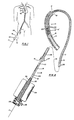
- FIG. 1 shows a general view of a mechanical atherectomy system 10 which is percutaneously introduced into a human femoral artery 11 at the groin area, and its distal end is snaked through the arterial system to reach a work site in a coronary artery 12.
- FIG. 2 shows an enlarged cross sectional view of a proximal end 13 and of a distal end 14, of the system 10.
- the distal end is inserted into the diseased coronary artery 12 (same numbers are used to indicated same items throughout the FIGS.) containing a blood clot 15′ seated on an atherosclerotic obstruction 15.
- the mid portion of the mechanical atherectomy system is represented by a phantom line 16.
- the system 10 comprises a flexible guide-wire 17 having a section at its distal eno shaped as an auger 18.
- the guide-wire is designed to be insertable through the human vascular system.
- a flexible rotary-catheter 19 has a wall 20 defining a longitudinal channel 21.
- the catheter 19 is rotatable and slidable over the guide-wire 17.
- a tubular-blade 22 is mounted to the distal end of the rotary-catheter 19.
- the tubular-blade 22 defines a through-hole 23 forming with the channel 21 a continuous passageway for accepting the obstruction material ingested into the through-hole.
- a motor 24 has a hollow tapered shaft 25 which couples to the proximal end of the flexible rotary-catheter through a matching tapered seat 30 for rotating it around the guide-wire 17.
- a sleeve 26 introduces the rotary-catheter into the vascular system and may be extended to separate the arterial wall from the rotating catheter and to deliver contrast and/or irrigating fluid to the work site.
- the sleeve 26 may be formed to a desired shape and serve as a guiding-catheter and assist in guiding the system through the vascular system to the work site.
- a port 27 is provided to accept fluids for delivery through the sleeve's distal end, and a seal 31 prevents the fluids from escaping out of the proximal end of the sleeve.
- a rotary joint 28 has a port 29 which is connected through the hollow shaft 25 to the channel 21 and can be used for delivering fluids to the work site or for creating a negative pressure in the channel 21 to assist in drawing the obstructon material into it.
- the guide-wire slidably passes through a close fitting hole formed at the end of the rotary joint 28.
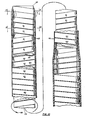
- FIG. 3 shows a first embodiment of a rotary-catheter 33 having means for diametrically stabilizing the rotary-catheter while transmitting torque and being bent, as for example when cleaning an obstruction located in the coronary arteries illustrated in FIG. 2.
- the diametrically stabilizing means is in the form of a series of hoop members 34 connected one to the other by the torque transmitting means in the form of strips 35.
- the hoops 34 and strips 35 form a skeleton of the rotary catheter on which a flexible plastic wall 38 is molded to define a channel 39.
- FIG. 4 shows a shape cut out of a flat thin material such as stainless steel sheet, including horizontal strips 34′ inter-connected by the inclined strips 35.
- the horizontal strips 34′ are folded and their ends bonded, or welded, to form the diametrically rigid hoops.
- the ends of the strips 34′ can be made to butt and bond along the inclined line 40 to avoid local double thickness of the hoop at the point of connection.
- the hoops' rigidity can be enhanced by giving them a slight arced cross section as shown in FIG. 3.
- the thin strips 35 bend easily, but only in one direction, therefore they are phased at third of a circle intervals, as shown in FIG. 3 so that every three consecutive hoops act as a miniature universal-joint that can bend in any direction while transmitting rotation and torque.
- the paddles can be formed by cutting a rectangular slot 53 along three of its sides and bending the material inwards around the fourth side which is left intact.
- the paddles 52 assist in pulling the obstruction material into the rotary-catheter 33 by turning the cut obstruction material that enter the through-hole around the stationary auger, and also by being inclined themselves the paddles operate as inclined planes to move the material into the rotary-catheter 33.
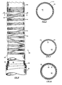
- FIG. 8 shows a second embodiment of a rotary-catheter 88 wherein the hoop members are a few closely spaced windings 41 connected one to the other by a widely spaced partial winding 42.
- the closely spaced windings 41 can be brazed together to increase their diametrical stability.
- the widely spaced partial windings 42 serve to transmit torque from one hoop to the other.
- a tubular toothed blade 43 is brazed to the distal end of a skeleton (defined hereinafter).
- the rotary-catheter 88 comprises a neck section which extends from the blade 43 down to a point 44 at which point the rotary-catheter diameter increases to form a shaft section 45 with an increased torque transmitting capacity.
- the winding 41, 42 and 48 (which is the continuation of the windings in the shaft section) form a skeleton over which a flexible plastic wall 46 is formed to complete the rotary-catheter's structure and define a channel 49 therein.
- FIG. 10 shows a third embodiment 111 of a rotary catheter wherein the means for diametrically stabilizing and for transmitting torque comprise a helix 61 wound in the direction of rotation (which means that moving along the coils of the helix in the direction of rotation illustrated by arrow 66 on FIG. 10, while the helix is stationary, would cause advancing from the proximal end to the distal end).
- Such windings would tend to diametrically expand when the motor 24 drives the rotary-catheter 111 in the direction of the arrow 66, however, a second helix 62 wound in the counter-rotation direction tends to contract and thereby restrain the expansion of the first helix 61 and assist it in transmitting torque.
- a flexible plastic wall 63 seals a channel 69 defined by the rotary-catheter 111 so that negative pressue or flid introduced at its proximal end would reach its distal end.
- a thin plastic layer can be inlaid between the helixes to minimize friction betwen them.
- the helixes When the helixes are made of flat ribbon material as shown in FIG. 10 they form a wall which does not seal fluids effectively but may be sufficient for the purposes of mechanically containing the cut obstruction particles without the benefit of the plastic layer 63. Therefore, if fluid conveyance or suction through the rotary catheter are not contemplated, the plastic wall 63 may be omitted to increase flexibility and decrease wall thickness of the rotary-catheter, and a thin slippery coating may be applied to the ribbons which are used to form the helixes, to minimize friction between the helixes and of the helixes with their surroundings.
- a tubular blade 64 is made as an integral part of helixes 61 and 62, the last few coils of which are brazed together at their distal end and then sharpened
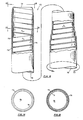
- FIG. 13 shows a partially sectioned view of the fourth embodiment 113 of the rotary-catheter wherein the means for diametricaly stabilizing and for transmitting torque comprise a helix 71 wound in the direction of rotation (which means that moving along the coils of the helix in the direction of rotation illustrated by arrow 66 on FIG. 10, while the helix is stationary, would cause advancing from the proximal end to the distal end).
- the means for diametricaly stabilizing and for transmitting torque comprise a helix 71 wound in the direction of rotation (which means that moving along the coils of the helix in the direction of rotation illustrated by arrow 66 on FIG. 10, while the helix is stationary, would cause advancing from the proximal end to the distal end).
- an external restraining member in the form of a flexible wall 73 restrains such expansion (the wall's cross sectional marking is standard, single line marking so as not to obscure a cord 76 which is integrated therein).
- the wall restraining action is reinforced by peripheral restraining means 76 in the form of cord made of, for example, nylon or aramid fibers which restrain the diametrical expansion of the helix 71 but have little effect on the wall's ability to stretch along its longitudinal axis and therefore on its ability to bend as shown in FIGS. 1 and 2.
- the wall 73 defines a fluid worthy channel 79.
- a tubular blade 74 is made as an integral part of the helix 71, the last few coils of which are brazed together at their distal end and then sharpended.
- the present invention puts in the hand of the physician a method to immediately and effectively intervene in what is often referred to as a "heart attack" which is commonly caused by an obstruction made of a soft fresh blood clot formed on an atherosclerotic plaque which has developed for several years.
- a "heart attack” which is commonly caused by an obstruction made of a soft fresh blood clot formed on an atherosclerotic plaque which has developed for several years.
- angioplasty since angioplasty may dislodge and release downstream some of the blood clot's material causing additional arterial occlusions possibly at points which would be more difficult to treat or points where no alternate blood supply exists (at the point of the original obstruction, being an "old” obstruction, alternate blood supply may have developed).
- the process for removing an obstruction made of a soft blood clot 15′ formed on an atherosclerotic plaque from a blood vessel comprises the following steps: inserting into the blood vessel a guide wire 17 and advancing it into the blood clot 15 which formed on the obstructon 15, inserting into the blood vessel, over the guide wire, the flexible rotary-catheter 19 having a poximal end 13 and distal end 14 with a tubular-blade 22 affixed thereto, advancing the distal end 14 to mechanically engage and unseat the blood clot 15′ while applying suction to port 29 to suck the blood clot 15′ into the through-hole 33, advancing the tubular-blade 22 to rotatably engage and peripherally cut the atherosclerotic plaque of the obstruction 15, removing the blood clot, the atherosclerotic plaque and the flxible rotary-catheter 19 out of the blood vessel 12.
- a tubular-blade is efficient and requires less energy input, in comparison to blades used in alternative mechnical systems which pulverize the obstruction material.
- the tubular-blade 22 peripherally cuts and extracts an obstruction with an outside diameter of 3mm, an inside diameter (lumen) of 1mm and a length of 10mm the area that the tubular-blade 22 has to cut through is approximately 100 square mm.
- a conventional blade for example as shown in US patent 4,445,509 by Auth, is used to break the same obstruction to shavings measuring .1mm by .1mm by 1mm the area that the conventional blade would have had to cut through is approximately 3800 square mm, and this much larger area requires a much larger energy input to the blade increasing the probability of traumatizing the artery. Further, the hollow construction of the flexible rotary-catheter enables it to swallow the obstruction material as it is being cut for efficient removal thereof.
Abstract
A mechanical atherectomy system (10) insertable into a human blood vessel (11) over a flexible guide-wire (17) for remotely cutting and removing an obstruction therein, having a diametrically stabilized torque transmitting flexible rotary catheter (19) equipped with a tubular blade (22) at its distal end, and a motor (24) connected to its proximal end. Cut material may be removed through a central channel (21) within the catheter by means of a suction pump.
Description
- With age a large portion of the population develops arterial obstructions formed by fats, fibrous material and calcified deposits, resulting in a diminished blood circulation. These obstructions can induce blood clots which further diminish or block the blood flow. When this occurs in the coronary arteries serving the heart muscles it is referred to as a heart attack. Presently such obstructions are bypassed with a graft or they are treated by angioplasty using a catheter equipped with a ballon which is inserted, over a guide wire, into the obstructon through the arterial system and then inflated to dilate the obstruction's lumen. Problems with this treatment are that it injures the aeterial wall and may burst it. In certain cases it is ineffective. It creates a rough lumen. It does not remove the obstructing material out of the vascular system and may even release obstruction material into the vascular system. Thus, angioplasty during a heart attack carries the risk of dislodging particles of the blood clot and allowing them to move down stream creating further, potentially critical, damage.
- An objective of the present invention is to provide a flexible torque transmitting rotary catheter for a mechanical atherectomy system which can be percutaneously or intra-operatively introduced into the vascular system for cutting and removing an obstruction therein. The rotary-catheter is insertable and rotatable over a guide-wire and transmits rotation and torque to a blade affixed at its distal end from a motor affixed to its proximal end.
- A further objective of the present invention is to provide a flexible rotary-catheter that would positively remove out of the human body the obstrucion material, including blood clots if present, create a smooth lumen, and would minimize injury to the blood vessel's wall.
- A further objective of the invention is to provide a system that can be used actually during a heat attack to provide an immediate relief and a long term correction of the diseased arterial site.
- The flexible rotary catheter should be produceable in diameters down to around 1mm (millimeter) and a length of up to a meter to be able to reach and enter small and remote blood vessels. Preferably, the procedure using the mechanical atherectomy system would resemble angioplasty so that present skills of the medical staff can be utilized.
- The rotary-catheter should be simultaneously flexible and capable of transmitting torque so that when it is introduced percutaneously to treat an obstruction in a remote artery, for example a coronary artery, it can assume a tortuous path of the vascular system including some sharp turns found in the coronary vascular system.
- These and other objectives of the invention will become apparent from the following discussion and the accompanying drawings.
-
- FIG. 1 shows a general view of a mechanical atherectomy system being inserted into an obstructed human coronary artery. The mechanical atherectomy system is introduced into the vascular system percutaneously at the groin area and is snaked through the arterial system to reach the work site where the obstruction is about to be removed.
- FIG. 2 shows a cross sectional view of the proximal and distal ends of the mechanical atherectomy system with its distal end inserted into an obstructed coronary artery. The general positioning of the parts corresponds to their position in FIG. 1. Due to space limitations on the drawing sheets a segment or segments of the mechanical atherectomy system and rotary catheter are omitted and in FIG. 2 the mid section of the system is represented by a phantom line.
- FIG. 3 shows a partially sectional view of a first embodiment of a rotary-catheter.
- FIG. 4 shows a skelton member of the rotary-catheter of the first embodiment in its flat position before it has been rolled to form the intermittent tube shown in FIG. 3
- FIG. 5 shows an end view of a first embodiment viewed along line 5-5 marked on FIG. 3.
- FIG. 6 shows a cross sectional view of the first embodiment as viewed along line 6-6 marked on FIG. 3.
- FIG. 7 shows a cross sectional view of the first embodiment as viewed along line 7-7 marked on FIG. 3
- FIG. 8 shows a partially sectioned view of a second embodiment of a rotary-catheter.
- FIG. 9 shows a cross sectional view of the second embodiment as viewed along line 9-9 marked on FIG. 8.
- FIG. 10 shows a sectioned view of a third embodiment of the rotary catheter.
- FIG. 11 shows a cross sectional view of the third embodiment as viewed along a line 11-11 marked on FIG. 10.
- FIG. 12 shows a cross sectional view of the third embodiment as viewed along line 12-12 marked on FIG. 10.
- FIG. 13 shows a cross sectional view of a fourth embodiment of the rotary-catheter.
- FIG. 14 shows an end view of the fourth embodiment as viewed along a line 14-14 marked on FIG. 13.
- FIG. 15 shows a cross sectional view of the fourth embodiment as viewed along a line 15-15 marked on FIG. 13.
- FIG. 1 shows a general view of a
mechanical atherectomy system 10 which is percutaneously introduced into a human femoral artery 11 at the groin area, and its distal end is snaked through the arterial system to reach a work site in acoronary artery 12. - FIG. 2 shows an enlarged cross sectional view of a
proximal end 13 and of adistal end 14, of thesystem 10. The distal end is inserted into the diseased coronary artery 12 (same numbers are used to indicated same items throughout the FIGS.) containing ablood clot 15′ seated on anatherosclerotic obstruction 15. The mid portion of the mechanical atherectomy system is represented by aphantom line 16. - The
system 10 comprises a flexible guide-wire 17 having a section at its distal eno shaped as anauger 18. The guide-wire is designed to be insertable through the human vascular system. - A flexible rotary-
catheter 19 has awall 20 defining alongitudinal channel 21. Thecatheter 19 is rotatable and slidable over the guide-wire 17. A tubular-blade 22 is mounted to the distal end of the rotary-catheter 19. The tubular-blade 22 defines a through-hole 23 forming with the channel 21 a continuous passageway for accepting the obstruction material ingested into the through-hole. - A
motor 24 has a hollowtapered shaft 25 which couples to the proximal end of the flexible rotary-catheter through a matching taperedseat 30 for rotating it around the guide-wire 17. - A
sleeve 26 introduces the rotary-catheter into the vascular system and may be extended to separate the arterial wall from the rotating catheter and to deliver contrast and/or irrigating fluid to the work site. Thesleeve 26 may be formed to a desired shape and serve as a guiding-catheter and assist in guiding the system through the vascular system to the work site. Aport 27 is provided to accept fluids for delivery through the sleeve's distal end, and aseal 31 prevents the fluids from escaping out of the proximal end of the sleeve. - A
rotary joint 28 has aport 29 which is connected through thehollow shaft 25 to thechannel 21 and can be used for delivering fluids to the work site or for creating a negative pressure in thechannel 21 to assist in drawing the obstructon material into it. The guide-wire slidably passes through a close fitting hole formed at the end of therotary joint 28. - FIG. 3 shows a first embodiment of a rotary-
catheter 33 having means for diametrically stabilizing the rotary-catheter while transmitting torque and being bent, as for example when cleaning an obstruction located in the coronary arteries illustrated in FIG. 2. The diametrically stabilizing means is in the form of a series ofhoop members 34 connected one to the other by the torque transmitting means in the form ofstrips 35. Collectively thehoops 34 and strips 35 form a skeleton of the rotary catheter on which a flexibleplastic wall 38 is molded to define achannel 39. - FIG. 4 shows a shape cut out of a flat thin material such as stainless steel sheet, including
horizontal strips 34′ inter-connected by theinclined strips 35. At a later stage thehorizontal strips 34′ are folded and their ends bonded, or welded, to form the diametrically rigid hoops. As shown in FIG. 5 the ends of thestrips 34′ can be made to butt and bond along the inclined line 40 to avoid local double thickness of the hoop at the point of connection. The hoops' rigidity can be enhanced by giving them a slight arced cross section as shown in FIG. 3. Thethin strips 35 bend easily, but only in one direction, therefore they are phased at third of a circle intervals, as shown in FIG. 3 so that every three consecutive hoops act as a miniature universal-joint that can bend in any direction while transmitting rotation and torque. - During the manufacturing process, while the material is still flat, as shown in FIG. 4, it can be readily accessed with tools and dies, and
teeth 51 andpaddles 52 can be relatively easily fabricated onto it. The paddles can be formed by cutting arectangular slot 53 along three of its sides and bending the material inwards around the fourth side which is left intact. Thepaddles 52 assist in pulling the obstruction material into the rotary-catheter 33 by turning the cut obstruction material that enter the through-hole around the stationary auger, and also by being inclined themselves the paddles operate as inclined planes to move the material into the rotary-catheter 33. - Since the torque that is transmitted through the rotary-catheter gradually increases with distance from its distal end due to additive frictional losses along the rotary-catheter, it is desirable to correspondingly increase the torque transmitting capacity of the rotary-catheter. As shown in FIG. 4
horizontal strips 36 andvertical strips 37 have been made longer and wider, respectively, increasing the rotary-catheter diameter (note FIG. 3) and torque transmitting capacity (from hereon the small diameter and larger diameter catheter sections will be referred to as the neck and shaft section, respectively). - FIG. 8 shows a second embodiment of a rotary-
catheter 88 wherein the hoop members are a few closely spacedwindings 41 connected one to the other by a widely spaced partial winding 42. The closely spacedwindings 41 can be brazed together to increase their diametrical stability. The widely spacedpartial windings 42 serve to transmit torque from one hoop to the other. A tubulartoothed blade 43 is brazed to the distal end of a skeleton (defined hereinafter). The rotary-catheter 88 comprises a neck section which extends from theblade 43 down to apoint 44 at which point the rotary-catheter diameter increases to form ashaft section 45 with an increased torque transmitting capacity. - The winding 41, 42 and 48 (which is the continuation of the windings in the shaft section) form a skeleton over which a flexible
plastic wall 46 is formed to complete the rotary-catheter's structure and define achannel 49 therein. The fact that the skeleton of the second embodiment is made of a continuous wire simplifies the handling and fabrication of the rotary catheter, however, notwithstanding this, individual hoop members can be used to stabilize the rotary catheter's diameter in which case the plastic wall itself transmits the torque. - FIG. 10 shows a third embodiment 111 of a rotary catheter wherein the means for diametrically stabilizing and for transmitting torque comprise a
helix 61 wound in the direction of rotation (which means that moving along the coils of the helix in the direction of rotation illustrated byarrow 66 on FIG. 10, while the helix is stationary, would cause advancing from the proximal end to the distal end). Such windings would tend to diametrically expand when themotor 24 drives the rotary-catheter 111 in the direction of thearrow 66, however, asecond helix 62 wound in the counter-rotation direction tends to contract and thereby restrain the expansion of thefirst helix 61 and assist it in transmitting torque. - A flexible
plastic wall 63 seals achannel 69 defined by the rotary-catheter 111 so that negative pressue or flid introduced at its proximal end would reach its distal end. Alternatively, a thin plastic layer can be inlaid between the helixes to minimize friction betwen them. - When the helixes are made of flat ribbon material as shown in FIG. 10 they form a wall which does not seal fluids effectively but may be sufficient for the purposes of mechanically containing the cut obstruction particles without the benefit of the
plastic layer 63. Therefore, if fluid conveyance or suction through the rotary catheter are not contemplated, theplastic wall 63 may be omitted to increase flexibility and decrease wall thickness of the rotary-catheter, and a thin slippery coating may be applied to the ribbons which are used to form the helixes, to minimize friction between the helixes and of the helixes with their surroundings. - A
tubular blade 64 is made as an integral part ofhelixes - FIG. 13 shows a partially sectioned view of the
fourth embodiment 113 of the rotary-catheter wherein the means for diametricaly stabilizing and for transmitting torque comprise ahelix 71 wound in the direction of rotation (which means that moving along the coils of the helix in the direction of rotation illustrated byarrow 66 on FIG. 10, while the helix is stationary, would cause advancing from the proximal end to the distal end). Such windings would tend to diametrically expand when the motor drives therotary catheter 113 in the direction of thearrow 77, however, an external restraining member in the form of aflexible wall 73 restrains such expansion (the wall's cross sectional marking is standard, single line marking so as not to obscure acord 76 which is integrated therein). The wall restraining action is reinforced by peripheral restraining means 76 in the form of cord made of, for example, nylon or aramid fibers which restrain the diametrical expansion of thehelix 71 but have little effect on the wall's ability to stretch along its longitudinal axis and therefore on its ability to bend as shown in FIGS. 1 and 2. Thewall 73 defines a fluidworthy channel 79. - A
tubular blade 74 is made as an integral part of thehelix 71, the last few coils of which are brazed together at their distal end and then sharpended. - The present invention puts in the hand of the physician a method to immediately and effectively intervene in what is often referred to as a "heart attack" which is commonly caused by an obstruction made of a soft fresh blood clot formed on an atherosclerotic plaque which has developed for several years. Currently, the presence of the fresh blood clot, which has jelly like consistency, deters angioplasty since angioplasty may dislodge and release downstream some of the blood clot's material causing additional arterial occlusions possibly at points which would be more difficult to treat or points where no alternate blood supply exists (at the point of the original obstruction, being an "old" obstruction, alternate blood supply may have developed). Currently, several pharmacologic treatments are being tested that dissolve the blood clot, after which angioplasty may be performed, however, because the present invention is effective in releasing and removing blood clots as well as atherosclerotic plaque it circumvents the delay and added risks that the pharmacologic treatment introduces, such as for example bleeding elsewhere.
- The process for removing an obstruction made of a
soft blood clot 15′ formed on an atherosclerotic plaque from ablood vessel 12, comprises the following steps:
inserting into the blood vessel aguide wire 17 and advancing it into theblood clot 15 which formed on theobstructon 15,
inserting into the blood vessel, over the guide wire, the flexible rotary-catheter 19 having apoximal end 13 anddistal end 14 with a tubular-blade 22 affixed thereto,
advancing thedistal end 14 to mechanically engage and unseat theblood clot 15′ while applying suction toport 29 to suck theblood clot 15′ into the through-hole 33,
advancing the tubular-blade 22 to rotatably engage and peripherally cut the atherosclerotic plaque of theobstruction 15,
removing the blood clot, the atherosclerotic plaque and the flxible rotary-catheter 19 out of theblood vessel 12. - It should be noted that a tubular-blade is efficient and requires less energy input, in comparison to blades used in alternative mechnical systems which pulverize the obstruction material. To illustrate this point, when the tubular-
blade 22 peripherally cuts and extracts an obstruction with an outside diameter of 3mm, an inside diameter (lumen) of 1mm and a length of 10mm the area that the tubular-blade 22 has to cut through is approximately 100 square mm. If a conventional blade, for example as shown in US patent 4,445,509 by Auth, is used to break the same obstruction to shavings measuring .1mm by .1mm by 1mm the area that the conventional blade would have had to cut through is approximately 3800 square mm, and this much larger area requires a much larger energy input to the blade increasing the probability of traumatizing the artery. Further, the hollow construction of the flexible rotary-catheter enables it to swallow the obstruction material as it is being cut for efficient removal thereof. - While the present invention has been illustrated by a limited number of embodiments, it should be understood that various modifications and substitutions may be made without departing form the spirit of the invention or the scope of the claims.
Claims (22)
1. A mechanical atherectomy system insertable into a human blood vessel for remotely cutting and removing an obstruction therein, comprising in combination:
a flexible guide-wire insertable into said blood vessel,
a flexible rotary-catheter defining a channel and having distal and proximal ends, said flexible rotary-catheter being rotatably disposed and slidable over said guide-wire, a tubular-blade mounted to said distal end, said tubular-blade having a through hole forming with said channel a continuous passage for passing obstruction material ingested into said through-hole, into said flexible rotary-catheter,
coupling means at said proximal end of said flexible rotary-catheter for rotating said flexible rotary-catheter and said tubular-blade around said guide-wire,
means for a dimetrically stabilizing and means for transmitting torque being incorporated in said flexible rotary-catheter.
2. A mechanical atherectomy system as in claim 1, wherein said means for diametrically stabilizing said rotary-catheter comprise a series of hoop members
connected one to the other by said torque transmittng means.
connected one to the other by said torque transmittng means.
3. A mechanical atherectomy system as in claim 2, wherein said hoop members are rolled strips connected one to the other by strips.
4. A mechanical atherectomy system as in claim 2, wherein said hoop members are closely spaced windings connected one to the other by a widely spaced winding.
5. A mechanical atherectomy system as in claim 1, wherein said means for diametrically stabilizing comprise a helix wound in the direction of rotation, an external member restraining the expansion of said helix, said helix carrying at least part of the torque transmitted through said flexible rotary-catheter.
6. A mechanical atherectomy system as in claim 5, wherein said external restraining member comprises a helix wound in the counter rotation direction.
7. A mechanical atherectomy system as in claim 5, wherein said external restraining member comprises a flexible wall.
8. A mechanical atherectomy system as in claim 7, wherein said flexible wall contains eripheral restraining means.
9. A mechanical atherectomy system as in claim 1, wherein said tubular blade is an integral part of said means for diametrically stabilizing said flexible rotary-catheter.
10. A mechanical atherectomy system as in claim 1, wherein said tubular blade is an integral part of said means for transmitting torque.
11. A process for removing from a human blood vessel a soft blood clot,comprising the following steps:
inserting into said blood vessel a guide-wire and advancing it into said blood clot,
inserting into said blood vessel, over said guide wire, a flexible rotary-catheter having distal and proximal ends, advancing said distal end to mechanically engage and unseat said blood clot while applying suction to said proximal end to suck said blood clot into said distal end,
removing said blood clot and said catheter out of said blood vessel.
12. A process as in claim 11, wherein, at least a portion of said guide-wire is shaped as an auger.
13. A process for removing from a human blood vessel an obstruction made of a soft blood clot formed on an atherosclerotic plaque, comprising the following steps:
inserting into said blood vessel a guide-wire and advancing it into said blood clot,
inserting into said blood vessel, over said guide wire, a flexible rotary-catheter having a proximal end and a distal end with a tubular blade affixed to said distal end,
advancing said distal end to mechanically engage and unseat said blood clot while applying suction to said proximal end to suck such blood clot into said distal end,
rotating and advancing said tubular blade to peripherally cut and swallow said atherosclerotic plaque,
removing said blood clot, said atherosclerotic plaque and said catheter out of said blood vessel.
14. A process as in claim 13, wherein, at least a portion of said guide-wire is shaped as an auger.
15. A mechanical atherectomy system insertable into a human blood vessel for remotely cutting and removing an obstruction therein, comprising in combination:
a flexible guide wire insertable into said blood vessel,
a flexible rotary-catheter defining a channel and having distal and proximal ends, said flexible rotary-catheter being rotatably disposed and slidable over said guide-wire, a tubular-blade mounted to said distal end, said tubular-blade having a through-hole forming with said channel an inner wall which defines a continuous passage for accepting ingested obstruction,
said inner wall having inclined plane means which assist in pulling the obstruction material into the continuous passage,
coupling means at said proximal end of said flexible rotary catheter for rotating said flexible rotary-catheter and said tubular blade around said guide wire.
16. A mechanical atherectomy system as in claim 15, wherein said flexible rotary-catheter is rotatably disposed in a sleeve.
17. A mechanical atherectomy system as in claim 15, wherein said flexible rotary-catheter comprises a helix wound in the direction of rotation.
18. A mechanical atherectomy system as in claim 17, wherein said flexible rotary-catheter is rotatably disposed in a sleeve.
19. A mechanical atherectomy system as in claim 17, wherein a restraining member surrounds said helix and restrains its diametrical expansion.
20. A mechanical atherectomy system as in claim 19, wherein said restraining member comprises a helix wound in the counter rotation direction.
21. A mechanical atherectomy system as in claim 19, wherein said restraining member comprises a flexible wall.
22. A mechanical atherectomy system as in claim 21, wherein said flexible wall contains peripheral restraining means.
Priority Applications (4)
| Application Number | Priority Date | Filing Date | Title |
|---|---|---|---|
| US07/078,042 US4819634A (en) | 1984-05-14 | 1987-07-27 | Rotary-catheter for atherectomy system |
| CA000577462A CA1329531C (en) | 1987-07-27 | 1988-09-15 | Rotary-catheter for atherectomy system |
| EP19880308555 EP0358825A1 (en) | 1987-07-27 | 1988-09-16 | Rotary-catheter for atherectomy system |
| DE1988308555 DE358825T1 (en) | 1988-09-16 | 1988-09-16 | ROTATING CATHETER FOR ATHEREECTOMY SYSTEM. |
Applications Claiming Priority (3)
| Application Number | Priority Date | Filing Date | Title |
|---|---|---|---|
| US07/078,042 US4819634A (en) | 1984-05-14 | 1987-07-27 | Rotary-catheter for atherectomy system |
| CA000577462A CA1329531C (en) | 1987-07-27 | 1988-09-15 | Rotary-catheter for atherectomy system |
| EP19880308555 EP0358825A1 (en) | 1987-07-27 | 1988-09-16 | Rotary-catheter for atherectomy system |
Publications (1)
| Publication Number | Publication Date |
|---|---|
| EP0358825A1 true EP0358825A1 (en) | 1990-03-21 |
Family
ID=27168046
Family Applications (1)
| Application Number | Title | Priority Date | Filing Date |
|---|---|---|---|
| EP19880308555 Withdrawn EP0358825A1 (en) | 1984-05-14 | 1988-09-16 | Rotary-catheter for atherectomy system |
Country Status (3)
| Country | Link |
|---|---|
| US (1) | US4819634A (en) |
| EP (1) | EP0358825A1 (en) |
| CA (1) | CA1329531C (en) |
Cited By (7)
| Publication number | Priority date | Publication date | Assignee | Title |
|---|---|---|---|---|
| EP0393834A2 (en) * | 1989-03-16 | 1990-10-24 | Samuel Shiber | Rotary catheter for atherectomy system |
| EP0448859A2 (en) * | 1990-03-27 | 1991-10-02 | Samuel Shiber | Guided atherectomy system |
| FR2667238A1 (en) * | 1990-09-28 | 1992-04-03 | Peyrou Pierre | ANCILLARY PERCUTANEOUS DISCECTOMY MATERIAL IN THE TREATMENT OF DISCAL HERNIA. |
| US8663259B2 (en) | 2010-05-13 | 2014-03-04 | Rex Medical L.P. | Rotational thrombectomy wire |
| US8764779B2 (en) | 2010-05-13 | 2014-07-01 | Rex Medical, L.P. | Rotational thrombectomy wire |
| US9023070B2 (en) | 2010-05-13 | 2015-05-05 | Rex Medical, L.P. | Rotational thrombectomy wire coupler |
| US9795406B2 (en) | 2010-05-13 | 2017-10-24 | Rex Medical, L.P. | Rotational thrombectomy wire |
Families Citing this family (105)
| Publication number | Priority date | Publication date | Assignee | Title |
|---|---|---|---|---|
| US5443443A (en) * | 1984-05-14 | 1995-08-22 | Surgical Systems & Instruments, Inc. | Atherectomy system |
| US5334211A (en) * | 1984-05-14 | 1994-08-02 | Surgical System & Instruments, Inc. | Lumen tracking atherectomy system |
| US4909781A (en) * | 1988-04-08 | 1990-03-20 | Husted Royce Hill | Catheter with flexible cutter |
| GB8829182D0 (en) | 1988-12-14 | 1989-01-25 | Univ Birmingham | Surgical instrument |
| US5078723A (en) * | 1989-05-08 | 1992-01-07 | Medtronic, Inc. | Atherectomy device |
| US5269793A (en) * | 1989-07-20 | 1993-12-14 | Devices For Vascular Intervention, Inc. | Guide wire systems for intravascular catheters |
| ES2079483T3 (en) * | 1989-08-18 | 1996-01-16 | Evi Corp | CATHETER ATEROTOME. |
| US5211651A (en) * | 1989-08-18 | 1993-05-18 | Evi Corporation | Catheter atherotome |
| US5282484A (en) * | 1989-08-18 | 1994-02-01 | Endovascular Instruments, Inc. | Method for performing a partial atherectomy |
| US5156610A (en) * | 1989-08-18 | 1992-10-20 | Evi Corporation | Catheter atherotome |
| US5152744A (en) * | 1990-02-07 | 1992-10-06 | Smith & Nephew Dyonics | Surgical instrument |
| US5084010A (en) * | 1990-02-20 | 1992-01-28 | Devices For Vascular Intervention, Inc. | System and method for catheter construction |
| US5160342A (en) * | 1990-08-16 | 1992-11-03 | Evi Corp. | Endovascular filter and method for use thereof |
| AU660444B2 (en) * | 1991-02-15 | 1995-06-29 | Ingemar H. Lundquist | Torquable catheter and method |
| WO1993013704A1 (en) * | 1992-01-09 | 1993-07-22 | Endomedix Corporation | Bi-directional miniscope |
| US5643297A (en) * | 1992-11-09 | 1997-07-01 | Endovascular Instruments, Inc. | Intra-artery obstruction clearing apparatus and methods |
| US5792157A (en) * | 1992-11-13 | 1998-08-11 | Scimed Life Systems, Inc. | Expandable intravascular occlusion material removal devices and methods of use |
| US5836868A (en) * | 1992-11-13 | 1998-11-17 | Scimed Life Systems, Inc. | Expandable intravascular occlusion material removal devices and methods of use |
| US5501694A (en) * | 1992-11-13 | 1996-03-26 | Scimed Life Systems, Inc. | Expandable intravascular occlusion material removal devices and methods of use |
| US5490859A (en) * | 1992-11-13 | 1996-02-13 | Scimed Life Systems, Inc. | Expandable intravascular occlusion material removal devices and methods of use |
| US5897567A (en) * | 1993-04-29 | 1999-04-27 | Scimed Life Systems, Inc. | Expandable intravascular occlusion material removal devices and methods of use |
| US5417703A (en) * | 1993-07-13 | 1995-05-23 | Scimed Life Systems, Inc. | Thrombectomy devices and methods of using same |
| US5419774A (en) * | 1993-07-13 | 1995-05-30 | Scimed Life Systems, Inc. | Thrombus extraction device |
| US5571130A (en) * | 1994-10-04 | 1996-11-05 | Advanced Cardiovascular Systems, Inc. | Atherectomy and prostectomy system |
| US5863294A (en) * | 1996-01-26 | 1999-01-26 | Femrx, Inc. | Folded-end surgical tubular cutter and method for fabrication |
| US6379334B1 (en) * | 1997-02-10 | 2002-04-30 | Essex Technology, Inc. | Rotate advance catheterization system |
| EP1007139A1 (en) | 1997-02-12 | 2000-06-14 | Prolifix Medical, Inc. | Apparatus for removal of material from stents |
| US5882329A (en) * | 1997-02-12 | 1999-03-16 | Prolifix Medical, Inc. | Apparatus and method for removing stenotic material from stents |
| US7037316B2 (en) * | 1997-07-24 | 2006-05-02 | Mcguckin Jr James F | Rotational thrombectomy device |
| US5951480A (en) * | 1997-09-29 | 1999-09-14 | Boston Scientific Corporation | Ultrasound imaging guidewire with static central core and tip |
| US6001112A (en) | 1998-04-10 | 1999-12-14 | Endicor Medical, Inc. | Rotational atherectomy device |
| US6482217B1 (en) * | 1998-04-10 | 2002-11-19 | Endicor Medical, Inc. | Neuro thrombectomy catheter |
| US6666874B2 (en) | 1998-04-10 | 2003-12-23 | Endicor Medical, Inc. | Rotational atherectomy system with serrated cutting tip |
| US8328829B2 (en) * | 1999-08-19 | 2012-12-11 | Covidien Lp | High capacity debulking catheter with razor edge cutting window |
| US7708749B2 (en) | 2000-12-20 | 2010-05-04 | Fox Hollow Technologies, Inc. | Debulking catheters and methods |
| US7713279B2 (en) | 2000-12-20 | 2010-05-11 | Fox Hollow Technologies, Inc. | Method and devices for cutting tissue |
| US6299622B1 (en) | 1999-08-19 | 2001-10-09 | Fox Hollow Technologies, Inc. | Atherectomy catheter with aligned imager |
| US7655016B2 (en) | 1999-09-17 | 2010-02-02 | Covidien | Mechanical pump for removal of fragmented matter and methods of manufacture and use |
| US6454775B1 (en) * | 1999-12-06 | 2002-09-24 | Bacchus Vascular Inc. | Systems and methods for clot disruption and retrieval |
| US7048717B1 (en) | 1999-09-27 | 2006-05-23 | Essex Technology, Inc. | Rotate-to-advance catheterization system |
| AU2614901A (en) | 1999-10-22 | 2001-04-30 | Boston Scientific Corporation | Double balloon thrombectomy catheter |
| US8414543B2 (en) | 1999-10-22 | 2013-04-09 | Rex Medical, L.P. | Rotational thrombectomy wire with blocking device |
| US6408649B1 (en) * | 2000-04-28 | 2002-06-25 | Gyrotron Technology, Inc. | Method for the rapid thermal treatment of glass and glass-like materials using microwave radiation |
| ES2436668T3 (en) | 2000-12-20 | 2014-01-03 | Covidien Lp | Catheter to remove atheromatous or thrombotic occlusive material |
| US6926725B2 (en) * | 2002-04-04 | 2005-08-09 | Rex Medical, L.P. | Thrombectomy device with multi-layered rotational wire |
| US8377035B2 (en) | 2003-01-17 | 2013-02-19 | Boston Scientific Scimed, Inc. | Unbalanced reinforcement members for medical device |
| US8246640B2 (en) | 2003-04-22 | 2012-08-21 | Tyco Healthcare Group Lp | Methods and devices for cutting tissue at a vascular location |
| US7553323B1 (en) | 2004-01-08 | 2009-06-30 | Perez Juan I | Steerable endovascular graft delivery system |
| US20050272976A1 (en) * | 2004-03-15 | 2005-12-08 | Olympus Corporation | Endoscope insertion aiding device |
| WO2005089629A1 (en) * | 2004-03-18 | 2005-09-29 | Olympus Corporation | Insertion device |
| WO2006007410A2 (en) * | 2004-06-16 | 2006-01-19 | Medtronic, Inc. | Minimally invasive coring vein harvester |
| WO2006093976A1 (en) | 2005-02-28 | 2006-09-08 | Spirus Medical Inc. | Rotate-to-advance catheterization system |
| US8414477B2 (en) | 2005-05-04 | 2013-04-09 | Olympus Endo Technology America Inc. | Rotate-to-advance catheterization system |
| US8235942B2 (en) | 2005-05-04 | 2012-08-07 | Olympus Endo Technology America Inc. | Rotate-to-advance catheterization system |
| US8343040B2 (en) * | 2005-05-04 | 2013-01-01 | Olympus Endo Technology America Inc. | Rotate-to-advance catheterization system |
| US7780650B2 (en) | 2005-05-04 | 2010-08-24 | Spirus Medical, Inc. | Rotate-to-advance catheterization system |
| US8317678B2 (en) | 2005-05-04 | 2012-11-27 | Olympus Endo Technology America Inc. | Rotate-to-advance catheterization system |
| US7645290B2 (en) * | 2005-05-05 | 2010-01-12 | Lucas Paul R | Multi-functional thrombectomy device |
| EP4292548A3 (en) | 2005-09-12 | 2024-02-28 | Boston Scientific Scimed, Inc. | Endovascular devices |
| US8083727B2 (en) | 2005-09-12 | 2011-12-27 | Bridgepoint Medical, Inc. | Endovascular devices and methods for exploiting intramural space |
| US7918870B2 (en) | 2005-09-12 | 2011-04-05 | Bridgepoint Medical, Inc. | Endovascular devices and methods |
| US11020141B2 (en) | 2005-09-12 | 2021-06-01 | Bridgepoint Medical, Inc. | Endovascular devices and methods |
| US8025655B2 (en) | 2005-09-12 | 2011-09-27 | Bridgepoint Medical, Inc. | Endovascular devices and methods |
| US20070138915A1 (en) * | 2005-12-16 | 2007-06-21 | Maureen Mulvihill | Piezoelectric micro-device for blockage removal |
| US8574220B2 (en) | 2006-02-28 | 2013-11-05 | Olympus Endo Technology America Inc. | Rotate-to-advance catheterization system |
| US8435229B2 (en) | 2006-02-28 | 2013-05-07 | Olympus Endo Technology America Inc. | Rotate-to-advance catheterization system |
| JP4504941B2 (en) * | 2006-04-25 | 2010-07-14 | テルモ株式会社 | Thrombus aspiration catheter |
| US20070276419A1 (en) | 2006-05-26 | 2007-11-29 | Fox Hollow Technologies, Inc. | Methods and devices for rotating an active element and an energy emitter on a catheter |
| US8419658B2 (en) * | 2006-09-06 | 2013-04-16 | Boston Scientific Scimed, Inc. | Medical device including structure for crossing an occlusion in a vessel |
| US11298511B2 (en) | 2006-11-21 | 2022-04-12 | Bridgepoint Medical, Inc. | Endovascular devices and methods for exploiting intramural space |
| US9060802B2 (en) | 2006-11-21 | 2015-06-23 | Bridgepoint Medical, Inc. | Endovascular devices and methods for exploiting intramural space |
| US10888354B2 (en) * | 2006-11-21 | 2021-01-12 | Bridgepoint Medical, Inc. | Endovascular devices and methods for exploiting intramural space |
| WO2008144033A2 (en) * | 2007-05-18 | 2008-11-27 | Spirus Medical, Inc. | Rotate-to-advance catheterizaton system |
| US8870755B2 (en) | 2007-05-18 | 2014-10-28 | Olympus Endo Technology America Inc. | Rotate-to-advance catheterization system |
| EP3659664A1 (en) * | 2007-10-22 | 2020-06-03 | Bridgepoint Medical, Inc. | Devices for crossing chronic total occlusions |
| EP2211765A1 (en) | 2007-11-02 | 2010-08-04 | Rex Medical, L.P. | Method of inserting a vein filter |
| US7841994B2 (en) | 2007-11-02 | 2010-11-30 | Boston Scientific Scimed, Inc. | Medical device for crossing an occlusion in a vessel |
| US8337425B2 (en) | 2008-02-05 | 2012-12-25 | Bridgepoint Medical, Inc. | Endovascular device with a tissue piercing distal probe and associated methods |
| US8202246B2 (en) | 2008-02-05 | 2012-06-19 | Bridgepoint Medical, Inc. | Crossing occlusions in blood vessels |
| US8784440B2 (en) * | 2008-02-25 | 2014-07-22 | Covidien Lp | Methods and devices for cutting tissue |
| EP2291128B1 (en) | 2008-04-28 | 2016-08-31 | Bridgepoint Medical, Inc. | Apparatus for crossing occlusions in blood vessels |
| KR101645754B1 (en) | 2008-10-13 | 2016-08-04 | 코비디엔 엘피 | Devices and methods for manipulating a catheter shaft |
| WO2010126882A1 (en) * | 2009-04-29 | 2010-11-04 | Fox Hollow Technologies, Inc. | Methods and devices for cutting and abrading tissue |
| RU2509538C2 (en) | 2009-05-14 | 2014-03-20 | ТАЙКО ХЕЛСКЕА ГРУП эЛПи | Cleanable atherectomy catheters and methods for using them |
| WO2011068932A1 (en) | 2009-12-02 | 2011-06-09 | Fox Hollow Technologies, Inc. | Methods and devices for cutting tissue |
| JP5511107B2 (en) * | 2009-12-11 | 2014-06-04 | コヴィディエン リミテッド パートナーシップ | Substance removal device and method with improved substance capture efficiency |
| US20150094733A1 (en) | 2010-05-04 | 2015-04-02 | Samuel Shiber | Rotary catheter drive unit containing seal-sets |
| US9907567B2 (en) | 2010-05-04 | 2018-03-06 | Samuel Shiber | Mechanical — pharmaceutical system for opening obstructed bodily vessels |
| US10952764B2 (en) | 2010-05-04 | 2021-03-23 | Samuel Shiber | Rotary catheter drive unit containing seal-sets |
| KR101493138B1 (en) | 2010-06-14 | 2015-02-12 | 코비디엔 엘피 | Material removal device |
| EP2632352B1 (en) | 2010-10-28 | 2017-04-12 | Covidien LP | Material removal device |
| CA2817213C (en) | 2010-11-11 | 2016-06-14 | Covidien Lp | Flexible debulking catheters with imaging and methods of use and manufacture |
| EP2744424B1 (en) * | 2011-08-17 | 2017-11-08 | Samuel Shiber | Adaptive rotary catheter for opening obstructed bodily vessels |
| WO2013033426A2 (en) | 2011-09-01 | 2013-03-07 | Covidien Lp | Catheter with helical drive shaft and methods of manufacture |
| US9532844B2 (en) | 2012-09-13 | 2017-01-03 | Covidien Lp | Cleaning device for medical instrument and method of use |
| KR101717387B1 (en) | 2012-11-08 | 2017-03-16 | 코비디엔 엘피 | Tissue-removing catheter including operational control mechanism |
| US9943329B2 (en) | 2012-11-08 | 2018-04-17 | Covidien Lp | Tissue-removing catheter with rotatable cutter |
| US20140261841A1 (en) * | 2013-03-14 | 2014-09-18 | Robert Bosch Gmbh | Kink resistant hose system with coil layer and method of manufacturing |
| US9526519B2 (en) | 2014-02-03 | 2016-12-27 | Covidien Lp | Tissue-removing catheter with improved angular tissue-removing positioning within body lumen |
| US9456843B2 (en) | 2014-02-03 | 2016-10-04 | Covidien Lp | Tissue-removing catheter including angular displacement sensor |
| WO2015200702A1 (en) | 2014-06-27 | 2015-12-30 | Covidien Lp | Cleaning device for catheter and catheter including the same |
| US10314667B2 (en) | 2015-03-25 | 2019-06-11 | Covidien Lp | Cleaning device for cleaning medical instrument |
| US10292721B2 (en) | 2015-07-20 | 2019-05-21 | Covidien Lp | Tissue-removing catheter including movable distal tip |
| US10314664B2 (en) | 2015-10-07 | 2019-06-11 | Covidien Lp | Tissue-removing catheter and tissue-removing element with depth stop |
| US10588656B2 (en) | 2017-11-10 | 2020-03-17 | Penumbra, Inc. | Thrombectomy catheter |
Citations (5)
| Publication number | Priority date | Publication date | Assignee | Title |
|---|---|---|---|---|
| GB191303531A (en) * | 1912-02-28 | 1913-07-31 | Louis Marie Clement Charnaux | Improvements in Probes, Cannulas, Surgical Drainage-tubes and the like. |
| US4445509A (en) * | 1982-02-04 | 1984-05-01 | Auth David C | Method and apparatus for removal of enclosed abnormal deposits |
| US4653496A (en) * | 1985-02-01 | 1987-03-31 | Bundy Mark A | Transluminal lysing system |
| EP0254414A1 (en) * | 1986-06-16 | 1988-01-27 | Samuel Shiber | A rotary catheter for removing an obstruction froma blood vessel |
| US4729763A (en) * | 1986-06-06 | 1988-03-08 | Henrie Rodney A | Catheter for removing occlusive material |
Family Cites Families (10)
| Publication number | Priority date | Publication date | Assignee | Title |
|---|---|---|---|---|
| US3773034A (en) * | 1971-11-24 | 1973-11-20 | Itt Research Institute | Steerable catheter |
| US3749086A (en) * | 1972-07-24 | 1973-07-31 | Medical Evaluation Devices & I | Spring guide with flexible distal tip |
| US4020829A (en) * | 1975-10-23 | 1977-05-03 | Willson James K V | Spring guide wire with torque control for catheterization of blood vessels and method of using same |
| US4368730A (en) * | 1981-02-12 | 1983-01-18 | Nigel Sharrock | Intravenous catheter |
| US4627436A (en) * | 1984-03-01 | 1986-12-09 | Innoventions Biomedical Inc. | Angioplasty catheter and method for use thereof |
| US4732154A (en) * | 1984-05-14 | 1988-03-22 | Surgical Systems & Instruments, Inc. | Rotary catheter system |
| JPH025799Y2 (en) * | 1986-02-07 | 1990-02-13 | ||
| US4728319A (en) * | 1986-03-20 | 1988-03-01 | Helmut Masch | Intravascular catheter |
| US4676249A (en) * | 1986-05-19 | 1987-06-30 | Cordis Corporation | Multi-mode guidewire |
| US4749376A (en) * | 1986-10-24 | 1988-06-07 | Intravascular Surgical Instruments, Inc. | Reciprocating working head catheter |
-
1987
- 1987-07-27 US US07/078,042 patent/US4819634A/en not_active Expired - Lifetime
-
1988
- 1988-09-15 CA CA000577462A patent/CA1329531C/en not_active Expired - Fee Related
- 1988-09-16 EP EP19880308555 patent/EP0358825A1/en not_active Withdrawn
Patent Citations (5)
| Publication number | Priority date | Publication date | Assignee | Title |
|---|---|---|---|---|
| GB191303531A (en) * | 1912-02-28 | 1913-07-31 | Louis Marie Clement Charnaux | Improvements in Probes, Cannulas, Surgical Drainage-tubes and the like. |
| US4445509A (en) * | 1982-02-04 | 1984-05-01 | Auth David C | Method and apparatus for removal of enclosed abnormal deposits |
| US4653496A (en) * | 1985-02-01 | 1987-03-31 | Bundy Mark A | Transluminal lysing system |
| US4729763A (en) * | 1986-06-06 | 1988-03-08 | Henrie Rodney A | Catheter for removing occlusive material |
| EP0254414A1 (en) * | 1986-06-16 | 1988-01-27 | Samuel Shiber | A rotary catheter for removing an obstruction froma blood vessel |
Cited By (16)
| Publication number | Priority date | Publication date | Assignee | Title |
|---|---|---|---|---|
| EP0393834A2 (en) * | 1989-03-16 | 1990-10-24 | Samuel Shiber | Rotary catheter for atherectomy system |
| EP0393834A3 (en) * | 1989-03-16 | 1991-01-09 | Samuel Shiber | Rotary catheter for atherectomy system |
| EP0680730A2 (en) | 1989-03-16 | 1995-11-08 | Samuel Shiber | Rotary catheter for atherectomy system |
| EP0680730A3 (en) * | 1989-03-16 | 1996-01-24 | Samuel Shiber | Rotary catheter for atherectomy system. |
| EP0448859A2 (en) * | 1990-03-27 | 1991-10-02 | Samuel Shiber | Guided atherectomy system |
| EP0448859A3 (en) * | 1990-03-27 | 1992-05-27 | Samuel Shiber | Guided atherectomy system |
| FR2667238A1 (en) * | 1990-09-28 | 1992-04-03 | Peyrou Pierre | ANCILLARY PERCUTANEOUS DISCECTOMY MATERIAL IN THE TREATMENT OF DISCAL HERNIA. |
| WO1992005742A1 (en) * | 1990-09-28 | 1992-04-16 | Peyrou Pierre Louis | Ancillary material for percutaneous dissectomy in the treatment of slipped discs |
| US8663259B2 (en) | 2010-05-13 | 2014-03-04 | Rex Medical L.P. | Rotational thrombectomy wire |
| US8764779B2 (en) | 2010-05-13 | 2014-07-01 | Rex Medical, L.P. | Rotational thrombectomy wire |
| US9023070B2 (en) | 2010-05-13 | 2015-05-05 | Rex Medical, L.P. | Rotational thrombectomy wire coupler |
| US9282992B2 (en) | 2010-05-13 | 2016-03-15 | Rex Medical, L.P. | Rotational thrombectomy wire |
| US9700346B2 (en) | 2010-05-13 | 2017-07-11 | Rex Medical, L.P. | Rotational thrombectomy wire |
| US9795406B2 (en) | 2010-05-13 | 2017-10-24 | Rex Medical, L.P. | Rotational thrombectomy wire |
| US10064645B2 (en) | 2010-05-13 | 2018-09-04 | Rex Medical, L.P. | Rotational thrombectomy wire |
| US10517630B2 (en) | 2010-05-13 | 2019-12-31 | Rex Medical, L.P. | Rotational thrombectomy wire |
Also Published As
| Publication number | Publication date |
|---|---|
| CA1329531C (en) | 1994-05-17 |
| US4819634A (en) | 1989-04-11 |
Similar Documents
| Publication | Publication Date | Title |
|---|---|---|
| US4819634A (en) | Rotary-catheter for atherectomy system | |
| US5007896A (en) | Rotary-catheter for atherectomy | |
| US5024651A (en) | Atherectomy system with a sleeve | |
| US4842579A (en) | Atherectomy device | |
| US5041082A (en) | Mechanical atherectomy system and method | |
| US5653696A (en) | Stent unclogging method | |
| US6482215B1 (en) | Adjustable vessel cleaner and method | |
| EP0375381B1 (en) | Atherectomy system | |
| US4957482A (en) | Atherectomy device with a positive pump means | |
| US4732154A (en) | Rotary catheter system | |
| CA2157697C (en) | Vascular incisor/dilator | |
| US4653496A (en) | Transluminal lysing system | |
| US5895400A (en) | Catheter with bristles | |
| US6113614A (en) | Medical device for dissolution of tissue within the human body | |
| EP0147192A2 (en) | Recanalisation catheter with cutter head | |
| EP0387980A1 (en) | Atherectomy system with a clutch | |
| US20050119615A1 (en) | Guidewire for crossing occlusions or stenoses | |
| JPH02104371A (en) | Atelectomy apparatus | |
| US6146397A (en) | Endarterectomy loop | |
| EP0353087B1 (en) | Atherectomy device | |
| JPH0295359A (en) | Mechanical atheroma removing apparatus | |
| CA2367280A1 (en) | Flexible-agitator system and method | |
| WO1999060934A1 (en) | Medical device for the transportation and dissolution of fluid and matter from within the human body | |
| EP0387451B1 (en) | Atherectomy system | |
| JPH06319745A (en) | Atheromatous occlusion eliminating device |
Legal Events
| Date | Code | Title | Description |
|---|---|---|---|
| PUAI | Public reference made under article 153(3) epc to a published international application that has entered the european phase |
Free format text: ORIGINAL CODE: 0009012 |
|
| AK | Designated contracting states |
Kind code of ref document: A1 Designated state(s): DE FR GB |
|
| 17P | Request for examination filed |
Effective date: 19900608 |
|
| EL | Fr: translation of claims filed | ||
| DET | De: translation of patent claims | ||
| 17Q | First examination report despatched |
Effective date: 19920508 |
|
| RAP3 | Party data changed (applicant data changed or rights of an application transferred) |
Owner name: SHIBER, SAMUEL |
|
| STAA | Information on the status of an ep patent application or granted ep patent |
Free format text: STATUS: THE APPLICATION IS DEEMED TO BE WITHDRAWN |
|
| 18D | Application deemed to be withdrawn |
Effective date: 19921120 |