EP0325272A2 - Drill bit with improved steerability - Google Patents
Drill bit with improved steerability Download PDFInfo
- Publication number
- EP0325272A2 EP0325272A2 EP89100960A EP89100960A EP0325272A2 EP 0325272 A2 EP0325272 A2 EP 0325272A2 EP 89100960 A EP89100960 A EP 89100960A EP 89100960 A EP89100960 A EP 89100960A EP 0325272 A2 EP0325272 A2 EP 0325272A2
- Authority
- EP
- European Patent Office
- Prior art keywords
- gage
- drill bit
- cutting
- bit
- borehole
- Prior art date
- Legal status (The legal status is an assumption and is not a legal conclusion. Google has not performed a legal analysis and makes no representation as to the accuracy of the status listed.)
- Granted
Links
Images
Classifications
-
- E—FIXED CONSTRUCTIONS
- E21—EARTH DRILLING; MINING
- E21B—EARTH DRILLING, e.g. DEEP DRILLING; OBTAINING OIL, GAS, WATER, SOLUBLE OR MELTABLE MATERIALS OR A SLURRY OF MINERALS FROM WELLS
- E21B17/00—Drilling rods or pipes; Flexible drill strings; Kellies; Drill collars; Sucker rods; Cables; Casings; Tubings
- E21B17/10—Wear protectors; Centralising devices, e.g. stabilisers
- E21B17/1092—Gauge section of drill bits
-
- E—FIXED CONSTRUCTIONS
- E21—EARTH DRILLING; MINING
- E21B—EARTH DRILLING, e.g. DEEP DRILLING; OBTAINING OIL, GAS, WATER, SOLUBLE OR MELTABLE MATERIALS OR A SLURRY OF MINERALS FROM WELLS
- E21B10/00—Drill bits
- E21B10/46—Drill bits characterised by wear resisting parts, e.g. diamond inserts
-
- E—FIXED CONSTRUCTIONS
- E21—EARTH DRILLING; MINING
- E21B—EARTH DRILLING, e.g. DEEP DRILLING; OBTAINING OIL, GAS, WATER, SOLUBLE OR MELTABLE MATERIALS OR A SLURRY OF MINERALS FROM WELLS
- E21B7/00—Special methods or apparatus for drilling
- E21B7/04—Directional drilling
- E21B7/06—Deflecting the direction of boreholes
- E21B7/064—Deflecting the direction of boreholes specially adapted drill bits therefor
Definitions
- the present invention relates generally to drill bits, and, more specifically, relates to drill bits conformed to provide improved steerability of the bit through unique design of the gage portions of the bit.
- Conventional drill bits typically include one or more cutting surfaces to initially cut the gage of the borehole, i.e., the nominal diameter of the borehole.
- This cutting element may be one of any of the conventional types of cutting elements, such as a discrete cutting element, [such as] a surface-set natural diamond cutter, or a cutting or abrasive matrix, such as is formed by sintering small, grit-size diamonds in an abradable matrix.
- gage pads typically include gage pads extending along the side of the bit to contact the sides of the borehole (as cut and defined by the gage cutting elements), to help maintain stability of the bit.
- Conventional gage pads typically provide relatively broad contact surfaces extending along 30-60% of the radial periphery of the bit.
- These gage pads are typically formed of diamond impregnated pads, of pads including vertical rows of diamonds (referred to as "broach stones") or of other wear-resistent materials such as tungstun carbide slugs. With the diamond impregnated pads, the diamond impregnation is utilized primarily to provide abrasion resistance to the bit gage pad as it rotates within the wellbore.
- the broach stone gage cutters are typically conformed to provide a minimal cutting capability to the gage pad.
- the primary purpose of gage pads in conventional bits is to maintain hole diameter and resist deviation from the borehole axis.
- Drill bits heretofore utilized for navigational drilling have, however, typically been of the conventional types as described above. However, such bits are better adapted, because of their gage design, for straight, rather than deviated, drilling of wellbores.
- the present invention provides new and improved drill bits and methods for constructing drill bits whereby the bits will exhibit improved steerability relative to conventional designs, thereby providing optimal performance in directional and navigational drilling environments.
- Drill bits in accordance with the present invention employ gage designs adapted to facilitate the bit's cutting an arcuate or curved path in a formation in response to side loading of the bit. This may be accomplished In different ways and with a variety of gage configurations intended to function as cutting means, in contrast to the prior art.
- the gage of the bit will be adapted to minimize contact with the side of the borehole by a surface other than a cutting surface.
- the gage portion of the bit will include cutting elements of a type adapted to cut the formations in which the bit is designed to operate.
- the bit includes two gage portions separated by a peripheral recess. This recess allows the bit to turn within the formation while the upper gage section will assure that the hole size is maintained throughout the turn while acting as a fulcrum to bit deviation.
- Drill bit 10 in accordance with the present invention, illustrated from a side view.
- Drill bit 10 includes a body member, indicated generally at 12, which includes a plurality of cutting pads, indicated generally at 14.
- Body member 12 is preferably a molded component fabricated through conventional metal matrix infiltration technology.
- Drill bit 10 also preferably includes a shank with a threaded portion adapted to couple bit 10 into a drill string.
- Cutting pads 14 each include a bottom cutting portion 16, generally that portion beneath gage line 18. Bottom cutting portions 16 are arranged in generally radial spokes, extending along the periphery of drill bit 10 from proximate the axial center of drill bit 10. Cutting pads 14 are depicted as including surface set natural diamond cutting elements, indicated generally and typically at 19. The depiction of these cutting elements is for illustrative purposes only, as any type of known or satisfactory cutting element may be used on drill bits in accordance with the present invention, including, for example, impregnated pads, thermally stable diamond cutters, poly-crystalline diamond cutters and tungsten carbide cutters. Unlike conventional bits, these cutting elements on bit 10 may preferably extend along the entire vertical length of cutting pads 14, both above and below gage line 18. The cutting elements 19 above gage line 18 may be of a different type than those on bottom cutting portions 16.
- Cutting pads 14 each include a gage cutting portion 20, which is that portion extending above gage line 18.
- a plurality of cutting elements for example, as indicated at 21a and 21b, are provided at gage line 18 to cut the nominal gage of the borehole.
- gage cutting portions 20 of cutting pads 14 depart from their radial/vertical placement on drill bit 10, and spiral around a portion of the periphery of drill bit 10.
- the spiraled gage cutting portions 20 spiral around bit 10 to lag gage cutters 21a, 21b as bit 10 is rotated in a borehole.
- portions 20 may also lead gage cutters 21a, 21b.
- a gap width (w), indicated generally at 22, is placed between the leading edge 24 of each gage cutting portion 20 and the exposure of cutting elements on that cutting portion 20.
- bit 10 As bit 10 is rotated in a formation to drill the formation and gage cutters 21a, 21b cut the gage of the formation, bit 10 will be progressing downwardly, penetrating the formation. Accordingly, cutters proximate leading edge 24 of the gage cutting portion 20 would not typically be providing actual cutting of the formation, but would merely be proceeding in the path of gage cutters 21a, 21b. Accordingly, in this exemplary embodiment, width (w) 22 is provided, thereby offsetting cutting elements 19 on spiraled gage cutting portions 20 where cutting elements 19 will be intersecting more of the formation.
- Offset width (w) 22 may be adapted for particular bits and particular cutter configurations, and may be functionally related to the depth of cut of bottom cutting portion 16 and the expected depth of penetration of the bit per revolution within the formation. Alternatively, offset width 22 may be omitted and cutting elements can be provided along the entire surface of spiraled gage cutting portion 20.
- drill bit 10 In operation within a well, drill bit 10 will exhibit improved steerability due to the contours of gage cutting portions 20 of cutting pads 14. This improved steerability can best be explained by comparison to a bit having vertically extending gage portions, such as if the gage portions of drill bit 10 continued the radial extension of bottom cutting portion 16.
- the drill bit When a drill bit is directed in a formation to drill a deviated wellbore, the drill bit is deflected within the established portion of the wellbore as it cuts along an arc.
- gage pads With a conventional drill bit having large, vertically extending, gage pads, the entire length of the gage pads will simultaneously contact a generally vertical line on the side of the formation. This line may be envisioned as lying along the innermost portion of the desired arcuate wellbore.
- gage cutting portion 20 does not serve as a standoff to prevent lateral cutting of bit 10, but is free to cut laterally in the formation.
- gage cutting portion 20 As bit 10 rotates and penetrates the formation, a new, vertically offset, point of gage cutting portion 20 is brought into contact with uncut formation material along the conceptualized path of the borehole. This new point is then free to cut the formation to which it is exposed, as are following points in turn.
- the side loading necessary to cause drill bit 10 to cut the sidewall of the borehole is substantially reduced.
- Drill bit 30 again includes a body section 32 and a plurality of cutting pads 34.
- Cutting pads 34 are arranged in spirals around respective portions of the periphery of drill bit 30.
- Each cutting pad 34 may be a generally continuous land which extends from proximate the longitudinal axis of bit 30 to substantially above gage line 36.
- each continuous land 34 surrounds an aperture 38 which directs a dedicated hydraulic flow regime across the cutting elements on cutting pads 34.
- Gage cutting portions 40 of continuous lands 34 may include cutting elements of the type as utilized on cutting pads 34 beneath gage line 36, although different types of cutting elements may also be employed.
- Gage cutting portions 40 of drill bit 30 function in a manner similar to that described with respect to gage cutting portions 20 of drill bit 10 of Fig. 1.
- the spiraled arrangements of cutting lands 34, particularly along gage cutting portions 40 minimize the side loading on bit 30 required to allow bit 30 to deflect within a wellbore.
- Drill bit 50 includes a plurality of bottom cutting pads 52, 54 which extend generally radially along the periphery of drill bit 50.
- Cutting pads 52 cut primarily along the bottom surface when drill bit 50 is operated within a formation, while cutting pads 54 extend to the gage 56 of bit 50.
- Cutting pads 52 thus extend from proximate the longitudinal axis of drill bit 50 to generally vertical above gage line 56.
- Each cutting pad 52, 54 preferably exhibits a generally triangular form along the periphery of drill bit 50.
- Each cutting pad 52, 54 may again, as in bit 30 of Fig. 2, be a generally continuous pad surrounding a central aperture 58, 60, respectively, to provide a dedicated hydraulic flow across each cutting pad 52, 54.
- Drill bit 50 further includes discrete gage cutting pads 62 which are preferably disposed in generally radial alignment with cutting pads 52.
- Gage cutting pads 62 preferably include cutting elements suitable for cutting the formations which bottom cutting pads are designed to cut.
- each gage cutting pad 62 will have cutting elements arranged primarily on the lower portion, for example the lower two-thirds, of the pad 62. This allows the lower portion of the gage cutting pad 62 to cut freely into the formation, while the upper portions will tend to function as a stand-off for bit 50.
- the upper portions of gage cutting pad 62 will preferably be formed of an abrasion resistant material, such as a diamond impregnated matrix, as discussed earlier herein.
- the distribution and sizing of discrete gage cutting pads 62 establishes a relatively wide angle ( ⁇ ) 64 between adjacent leading and trailing edges of neighboring gage cutting pads 62.
- ⁇ relatively wide angle
- Each gage cutting pad 62 extends upwardly from a position at or below gage line 56.
- gage cutting pads 62 In operation, as drill bit 50 is rotated and deflected within a borehole, these discrete gage cutting pads 62 will facilitate optimal steerability for bit 50. As drill bit 50 begins to cut an arc, the surfaces which normally tend to oppose deflection of the bit are gage cutting pads 62. However, because of the spacing of gage cutting pads 62, there is a distance around the periphery of drill bit 50, as a result of the angular spacing represented by angle ( ⁇ ) 64, which will not oppose deflection of bit 50.
- drill bit 50 may be considered as being capable of deflecting around a fulcrum defined by the adjacent leading and trailing edges of adjacent gage cutting pads 62, as indicated generally along dashed line 66 in Figures 3A-B or around a fulcrum 68 defined by the corresponding edges of cutting pads 54. Accordingly, as drill bit 50 is deflected and rotated within the formation, each pad cutting the gage dimension, 54, 62, will take a progressively deeper cut to the inner side of the arc trajectory, facilitating the cutting of the arc. Further, as the full dimension of the gage cutting pads 62 traverses downwardly through the formations, they will continue to cut the gage dimension.
- the cooperative arrangement of cutting pads 54 extending to the gage of bit 50, and the spaced distribution of relatively narrow gage cutting pads 62, as depicted on drill bit 50, serves to concentrate side loading on drill bit 50 when drill bit 50 is operated in a formation such that the side load is applied primarily to the side and gage cutting portions of the bit encountering the formation. Accordingly, the bit does not provide an undesirable resistance to steering along a desired nonlinear path, as is the case with prior art bits.
- Drill bit 70 again includes a body member 72 and a plurality of cutting pads 74.
- Cutting pads 74 each preferably extend radially, and may eventually be vertical, from proximate the longitudinal axis of drill bit 70 to lower gage line 76 of bit 70.
- Each cutting pad 74 again may surround a central aperture 78 to provide dedicated hydraulic flow across cutting pad 74.
- Drill bit 70 also includes an upper gage section, indicated generally at 80.
- Upper gage section defines an upper gage line 94 which is separated from lower gage line 76 by a separation distance 82.
- Upper gage section 80 includes a plurality of vertical gage cutting pads distributed around the periphery of drill bit 70. The portions of gage cutters 84 within separation distance include a radius 92 terminating at gage dimension.
- Upper gage section cutters are depicted as including cutting elements across their entire surface. In some configurations, it may be desirable to include cutting elements only proximate the lower portion of gage cutting pads 84 and to establish the upper portion of each gage pad 84 as merely a diamond impregnated pad, as previously described herein.
- separation distance 82 provides a relief to facilitate deflection of bit 70 and to thereby facilitate the drilling of the nonlinear path, because the cutting pads 74 do not have excessive resistance to side loading as in conventional bits, and gage cutting pads 84 provide a contact point against which bit 70 may turn. Since lower cutting pads 74 extend only a minimal distance above lower gage line 76, when side load forces are placed on drill bit 70, there is relatively minimal resistance to lateral cutting of the formation. Because of the dimensional relief provided by separation distance 82, upper gage line 94 may be considered the location of a fulcrum on the interior of the arc around which drill bit 70 can deflect.
- references herein to cutting or holding a gage dimension while the bit is traversing a nonlinear path are not meant to imply that the borehole is of perfect gage, or even symmetrical.
- Turning a bit will normally result in an oversized, generally elliptical cross-section, hole, with its longer dimension parallel to the direction of the turn.
- a generally circular but oversized hole in all radial dimensions may result.
- gage portions may be utilized which include relatively wide spiraled cutting pads to provide some nominal resistance to sideloading to prevent inadvertent deviation of the bit.
- conventional large, predominantly non-cutting gage pads may be utilized on a bit in conjunction with spiral and/or cutting gage pads as described herein.
- different cutting elements may be employed on various cutting pads. Reverse-directed spiral pads, discontinuous spirals or spirals disposed at varying angles may also be employed. Accordingly, it should be readily understood that the embodiments described and illustrated herein are illustrative only and are not to be considered as limitations on the present invention.
Abstract
Description
- The present invention relates generally to drill bits, and, more specifically, relates to drill bits conformed to provide improved steerability of the bit through unique design of the gage portions of the bit.
- Conventional drill bits typically include one or more cutting surfaces to initially cut the gage of the borehole, i.e., the nominal diameter of the borehole. This cutting element may be one of any of the conventional types of cutting elements, such as a discrete cutting element, [such as] a surface-set natural diamond cutter, or a cutting or abrasive matrix, such as is formed by sintering small, grit-size diamonds in an abradable matrix.
- Additionally, conventional drill bits typically include gage pads extending along the side of the bit to contact the sides of the borehole (as cut and defined by the gage cutting elements), to help maintain stability of the bit. Conventional gage pads typically provide relatively broad contact surfaces extending along 30-60% of the radial periphery of the bit. These gage pads are typically formed of diamond impregnated pads, of pads including vertical rows of diamonds (referred to as "broach stones") or of other wear-resistent materials such as tungstun carbide slugs. With the diamond impregnated pads, the diamond impregnation is utilized primarily to provide abrasion resistance to the bit gage pad as it rotates within the wellbore. The broach stone gage cutters are typically conformed to provide a minimal cutting capability to the gage pad. In summary, the primary purpose of gage pads in conventional bits is to maintain hole diameter and resist deviation from the borehole axis.
- The drilling of angled or "deviated" wellbores has been known for many years. However, techniques for drilling deviated wellbores through navigational drilling techniques are becoming increasingly sophisticated. These navigational drilling techniques may benefit from drill bits with improved steerability, i.e., an ability to respond to directional loading forces applied by steering apparatus. Drill bits heretofore utilized for navigational drilling have, however, typically been of the conventional types as described above. However, such bits are better adapted, because of their gage design, for straight, rather than deviated, drilling of wellbores.
- Accordingly, the present invention provides new and improved drill bits and methods for constructing drill bits whereby the bits will exhibit improved steerability relative to conventional designs, thereby providing optimal performance in directional and navigational drilling environments.
- Drill bits in accordance with the present invention employ gage designs adapted to facilitate the bit's cutting an arcuate or curved path in a formation in response to side loading of the bit. This may be accomplished In different ways and with a variety of gage configurations intended to function as cutting means, in contrast to the prior art. Preferably, the gage of the bit will be adapted to minimize contact with the side of the borehole by a surface other than a cutting surface. Preferably, the gage portion of the bit will include cutting elements of a type adapted to cut the formations in which the bit is designed to operate. In another preferred embodiment, the bit includes two gage portions separated by a peripheral recess. This recess allows the bit to turn within the formation while the upper gage section will assure that the hole size is maintained throughout the turn while acting as a fulcrum to bit deviation.
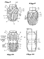
- Fig. 1 depicts, in pertinent part, an exemplary embodiment of a drill bit in accordance with the present invention, depicted from a side view.
- Fig. 2 depicts an alternative embodiment of a drill bit in accordance with the present invention, depicted from a side view.
- Figs. 3A-B depict another alternative embodiment of a drill bit in accordance with the present invention. Fig. 3A depicts the drill bit from a side view. Fig. 3B depicts the drill bit in a partial, bottom plan view.
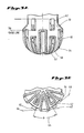
- Figs. 4A-B depict another alternative embodiment of a drill bit in accordance with the present invention. Fig. 4A depicts the drill bit from a side view. Fig. 4B schematically depicts the drill bit of Fig. 4A in a earth borehole, illustrated in vertical section.
- Referring now to Fig. 1, therein is depicted a
drill bit 10 in accordance with the present invention, illustrated from a side view.Drill bit 10 includes a body member, indicated generally at 12, which includes a plurality of cutting pads, indicated generally at 14.Body member 12 is preferably a molded component fabricated through conventional metal matrix infiltration technology.Drill bit 10 also preferably includes a shank with a threaded portion adapted tocouple bit 10 into a drill string. -
Cutting pads 14 each include abottom cutting portion 16, generally that portion beneathgage line 18.Bottom cutting portions 16 are arranged in generally radial spokes, extending along the periphery ofdrill bit 10 from proximate the axial center ofdrill bit 10.Cutting pads 14 are depicted as including surface set natural diamond cutting elements, indicated generally and typically at 19. The depiction of these cutting elements is for illustrative purposes only, as any type of known or satisfactory cutting element may be used on drill bits in accordance with the present invention, including, for example, impregnated pads, thermally stable diamond cutters, poly-crystalline diamond cutters and tungsten carbide cutters. Unlike conventional bits, these cutting elements onbit 10 may preferably extend along the entire vertical length ofcutting pads 14, both above and belowgage line 18. Thecutting elements 19 abovegage line 18 may be of a different type than those onbottom cutting portions 16. -
Cutting pads 14 each include agage cutting portion 20, which is that portion extending abovegage line 18. A plurality of cutting elements, for example, as indicated at 21a and 21b, are provided atgage line 18 to cut the nominal gage of the borehole. As can be seen in Fig. 1, abovegage line 18,gage cutting portions 20 ofcutting pads 14 depart from their radial/vertical placement ondrill bit 10, and spiral around a portion of the periphery ofdrill bit 10. In the illustrated embodiment, the spiraledgage cutting portions 20 spiral aroundbit 10 to laggage cutters bit 10 is rotated in a borehole. However,portions 20 may also leadgage cutters - Additionally, in the embodiment of Fig. 1, a gap width (w), indicated generally at 22, is placed between the leading
edge 24 of eachgage cutting portion 20 and the exposure of cutting elements on thatcutting portion 20. Asbit 10 is rotated in a formation to drill the formation andgage cutters bit 10 will be progressing downwardly, penetrating the formation. Accordingly, cutters proximate leadingedge 24 of thegage cutting portion 20 would not typically be providing actual cutting of the formation, but would merely be proceeding in the path ofgage cutters cutting elements 19 on spiraledgage cutting portions 20 where cuttingelements 19 will be intersecting more of the formation. Offset width (w) 22 may be adapted for particular bits and particular cutter configurations, and may be functionally related to the depth of cut ofbottom cutting portion 16 and the expected depth of penetration of the bit per revolution within the formation. Alternatively,offset width 22 may be omitted and cutting elements can be provided along the entire surface of spiraledgage cutting portion 20. - In operation within a well,
drill bit 10 will exhibit improved steerability due to the contours ofgage cutting portions 20 ofcutting pads 14. This improved steerability can best be explained by comparison to a bit having vertically extending gage portions, such as if the gage portions ofdrill bit 10 continued the radial extension ofbottom cutting portion 16. When a drill bit is directed in a formation to drill a deviated wellbore, the drill bit is deflected within the established portion of the wellbore as it cuts along an arc. With a conventional drill bit having large, vertically extending, gage pads, the entire length of the gage pads will simultaneously contact a generally vertical line on the side of the formation. This line may be envisioned as lying along the innermost portion of the desired arcuate wellbore. As a result, extremely high sideloading on the bit is required to cause this large surface to cut into the formation. This is true even where the gage pads include broach stones, as the entire length of the stones will be contacting the formation wall. During the drilling of an arc, this side loading requirement must continually be overcome as the bit is directed along a radius. - In contrast, when
drill bit 10 is directed along a radius in a formation, only a small portion, theoretically essentially a point contact, is made betweengage cutting portion 20 and a similar generally vertical line along the sidewall of the borehole. Accordingly,gage cutting portion 20 does not serve as a standoff to prevent lateral cutting ofbit 10, but is free to cut laterally in the formation. Asbit 10 rotates and penetrates the formation, a new, vertically offset, point ofgage cutting portion 20 is brought into contact with uncut formation material along the conceptualized path of the borehole. This new point is then free to cut the formation to which it is exposed, as are following points in turn. As a result, the side loading necessary to causedrill bit 10 to cut the sidewall of the borehole is substantially reduced. - Referring now to Fig. 2, therein is depicted the lower, cutting, portion of an alternative embodiment of a
drill bit 30 in accordance with the present invention.Drill bit 30 again includes abody section 32 and a plurality of cuttingpads 34. Cuttingpads 34 are arranged in spirals around respective portions of the periphery ofdrill bit 30. Eachcutting pad 34 may be a generally continuous land which extends from proximate the longitudinal axis ofbit 30 to substantially abovegage line 36. As illustrated by way of example and not of limitation, eachcontinuous land 34 surrounds anaperture 38 which directs a dedicated hydraulic flow regime across the cutting elements on cuttingpads 34. The use of a dedicated hydraulic flow regime on drill bit cutting pads is disclosed in the co-pending application of Gordon Tibbitts filed the same day as the present application and entitled "Methods and Apparatus for Establishing Hydraulic Flow Regime in Drill Bits," and assigned to the assignee of the present invention. -
Gage cutting portions 40 of continuous lands 34 (those portions above gage line 36), again may include cutting elements of the type as utilized on cuttingpads 34 beneathgage line 36, although different types of cutting elements may also be employed.Gage cutting portions 40 ofdrill bit 30 function in a manner similar to that described with respect togage cutting portions 20 ofdrill bit 10 of Fig. 1. The spiraled arrangements of cuttinglands 34, particularly alonggage cutting portions 40 minimize the side loading onbit 30 required to allowbit 30 to deflect within a wellbore. - Referring now to Figs. 3A-B, therein is depicted another alternative embodiment of a
drill bit 50 in accordance with the present invention.Drill bit 50 includes a plurality ofbottom cutting pads drill bit 50. Cuttingpads 52 cut primarily along the bottom surface whendrill bit 50 is operated within a formation, while cuttingpads 54 extend to thegage 56 ofbit 50. Cuttingpads 52 thus extend from proximate the longitudinal axis ofdrill bit 50 to generally vertical abovegage line 56. Eachcutting pad drill bit 50. Eachcutting pad bit 30 of Fig. 2, be a generally continuous pad surrounding acentral aperture pad -
Drill bit 50 further includes discretegage cutting pads 62 which are preferably disposed in generally radial alignment withcutting pads 52.Gage cutting pads 62 preferably include cutting elements suitable for cutting the formations which bottom cutting pads are designed to cut. Preferably, eachgage cutting pad 62 will have cutting elements arranged primarily on the lower portion, for example the lower two-thirds, of thepad 62. This allows the lower portion of thegage cutting pad 62 to cut freely into the formation, while the upper portions will tend to function as a stand-off forbit 50. The upper portions ofgage cutting pad 62 will preferably be formed of an abrasion resistant material, such as a diamond impregnated matrix, as discussed earlier herein. - The distribution and sizing of discrete
gage cutting pads 62 establishes a relatively wide angle (φ) 64 between adjacent leading and trailing edges of neighboringgage cutting pads 62. Eachgage cutting pad 62 extends upwardly from a position at or belowgage line 56. - In operation, as
drill bit 50 is rotated and deflected within a borehole, these discretegage cutting pads 62 will facilitate optimal steerability forbit 50. Asdrill bit 50 begins to cut an arc, the surfaces which normally tend to oppose deflection of the bit aregage cutting pads 62. However, because of the spacing ofgage cutting pads 62, there is a distance around the periphery ofdrill bit 50, as a result of the angular spacing represented by angle (φ) 64, which will not oppose deflection ofbit 50. By way of illustration only,drill bit 50 may be considered as being capable of deflecting around a fulcrum defined by the adjacent leading and trailing edges of adjacentgage cutting pads 62, as indicated generally along dashedline 66 in Figures 3A-B or around afulcrum 68 defined by the corresponding edges of cuttingpads 54. Accordingly, asdrill bit 50 is deflected and rotated within the formation, each pad cutting the gage dimension, 54, 62, will take a progressively deeper cut to the inner side of the arc trajectory, facilitating the cutting of the arc. Further, as the full dimension of thegage cutting pads 62 traverses downwardly through the formations, they will continue to cut the gage dimension. - The cooperative arrangement of cutting
pads 54 extending to the gage ofbit 50, and the spaced distribution of relatively narrowgage cutting pads 62, as depicted ondrill bit 50, serves to concentrate side loading ondrill bit 50 whendrill bit 50 is operated in a formation such that the side load is applied primarily to the side and gage cutting portions of the bit encountering the formation. Accordingly, the bit does not provide an undesirable resistance to steering along a desired nonlinear path, as is the case with prior art bits. - Referring now to Figs. 4A and 4B, therein is depicted another alternative embodiment of a
drill bit 70 in accordance with the present invention.Drill bit 70 again includes abody member 72 and a plurality of cuttingpads 74. Cuttingpads 74 each preferably extend radially, and may eventually be vertical, from proximate the longitudinal axis ofdrill bit 70 tolower gage line 76 ofbit 70. Eachcutting pad 74 again may surround acentral aperture 78 to provide dedicated hydraulic flow across cuttingpad 74. -
Drill bit 70 also includes an upper gage section, indicated generally at 80. Upper gage section defines anupper gage line 94 which is separated fromlower gage line 76 by aseparation distance 82.Upper gage section 80 includes a plurality of vertical gage cutting pads distributed around the periphery ofdrill bit 70. The portions ofgage cutters 84 within separation distance include aradius 92 terminating at gage dimension. Upper gage section cutters are depicted as including cutting elements across their entire surface. In some configurations, it may be desirable to include cutting elements only proximate the lower portion ofgage cutting pads 84 and to establish the upper portion of eachgage pad 84 as merely a diamond impregnated pad, as previously described herein. - When
drill bit 70 is operated to drill a nonlinear borehole path,separation distance 82 provides a relief to facilitate deflection ofbit 70 and to thereby facilitate the drilling of the nonlinear path, because thecutting pads 74 do not have excessive resistance to side loading as in conventional bits, andgage cutting pads 84 provide a contact point against which bit 70 may turn. Sincelower cutting pads 74 extend only a minimal distance abovelower gage line 76, when side load forces are placed ondrill bit 70, there is relatively minimal resistance to lateral cutting of the formation. Because of the dimensional relief provided byseparation distance 82,upper gage line 94 may be considered the location of a fulcrum on the interior of the arc around whichdrill bit 70 can deflect. As more and more of cuttingpads 84 encounter the formation, the resistance to deflection ofdrill bit 70 within the formation will increase. The separation distance, therefore, in combination with the number and size of uppergage cutting pads 84 and the cutting element distribution on eachpad 84 will cooperatively serve to define a radius whichdrill bit 70 can optimally traverse. It will be apparent that the dimension of separation distance may vary between different embodiments of bits. However, by way of example only, separation distances of from 1.25 inches to 3 inches may potentially advantageously be utilized in embodiments ofbit 70. Althoughupper gage section 80 ofdrill bit 70 is depicted as having vertically arranged cutting pads, these cutting pads could easily be arranged in spiraled or other curvilinear shapes along their respective portions of the periphery ofdrill bit 70. - It will be understood by one of ordinary skill in the art that references herein to cutting or holding a gage dimension while the bit is traversing a nonlinear path are not meant to imply that the borehole is of perfect gage, or even symmetrical. Turning a bit will normally result in an oversized, generally elliptical cross-section, hole, with its longer dimension parallel to the direction of the turn. In some instances, as for example where the turn is not entirely planar, a generally circular but oversized hole (in all radial dimensions) may result.
- It will also be appreciated that the use of the present invention in a bit may also be employed to reduce, enhance or otherwise control the bit's tendency to "sidetrack" to the right or left by varying its resistance to lateral displacement in the borehole.
- Many modifications and variations may be made in the techniques and structures described and illustrated herein without departing from the spirit and scope of the present invention. For example, gage portions may be utilized which include relatively wide spiraled cutting pads to provide some nominal resistance to sideloading to prevent inadvertent deviation of the bit. Additionally, conventional large, predominantly non-cutting gage pads may be utilized on a bit in conjunction with spiral and/or cutting gage pads as described herein. Also, different cutting elements may be employed on various cutting pads. Reverse-directed spiral pads, discontinuous spirals or spirals disposed at varying angles may also be employed. Accordingly, it should be readily understood that the embodiments described and illustrated herein are illustrative only and are not to be considered as limitations on the present invention.
Claims (15)
Applications Claiming Priority (2)
| Application Number | Priority Date | Filing Date | Title |
|---|---|---|---|
| US14629088A | 1988-01-20 | 1988-01-20 | |
| US146290 | 1988-01-20 |
Publications (3)
| Publication Number | Publication Date |
|---|---|
| EP0325272A2 true EP0325272A2 (en) | 1989-07-26 |
| EP0325272A3 EP0325272A3 (en) | 1990-02-07 |
| EP0325272B1 EP0325272B1 (en) | 1993-04-28 |
Family
ID=22516689
Family Applications (1)
| Application Number | Title | Priority Date | Filing Date |
|---|---|---|---|
| EP19890100960 Expired - Lifetime EP0325272B1 (en) | 1988-01-20 | 1989-01-20 | Drill bit with improved steerability |
Country Status (4)
| Country | Link |
|---|---|
| EP (1) | EP0325272B1 (en) |
| AU (1) | AU613142B2 (en) |
| CA (1) | CA1306245C (en) |
| DE (1) | DE68906166T2 (en) |
Cited By (4)
| Publication number | Priority date | Publication date | Assignee | Title |
|---|---|---|---|---|
| US5161167A (en) * | 1990-06-21 | 1992-11-03 | Mitsubishi Denki Kabushiki Kaisha | Semiconductor laser producing visible light |
| FR2743843A1 (en) * | 1996-01-24 | 1997-07-25 | D A T C Diamond And Tungsten C | DRILLING TOOL, PARTICULARLY FOR PERFORMING OIL DRILLING |
| FR2751372A1 (en) * | 1996-07-22 | 1998-01-23 | Total Sa | Relaxation drill bit with side cutters set behind a main cutting face |
| BE1012751A5 (en) * | 1997-09-08 | 2001-03-06 | Baker Hughes Inc | Blades rotary drill dirigeable aggression a longitudinal variable size front zone. |
Citations (6)
| Publication number | Priority date | Publication date | Assignee | Title |
|---|---|---|---|---|
| US2553701A (en) * | 1949-09-16 | 1951-05-22 | Willard F Comstock | Well drilling bit |
| US3318400A (en) * | 1965-03-31 | 1967-05-09 | Exxon Production Research Co | Hollow crown diamond bit |
| US3367430A (en) * | 1966-08-24 | 1968-02-06 | Christensen Diamond Prod Co | Combination drill and reamer bit |
| US3833077A (en) * | 1971-02-12 | 1974-09-03 | L Lavallee | Diamond drills |
| US3978933A (en) * | 1975-01-27 | 1976-09-07 | Smith International, Inc. | Bit-adjacent stabilizer and steel |
| US4176723A (en) * | 1977-11-11 | 1979-12-04 | DTL, Incorporated | Diamond drill bit |
-
1989
- 1989-01-18 AU AU28585/89A patent/AU613142B2/en not_active Expired - Fee Related
- 1989-01-19 CA CA000588595A patent/CA1306245C/en not_active Expired - Lifetime
- 1989-01-20 DE DE1989606166 patent/DE68906166T2/en not_active Expired - Fee Related
- 1989-01-20 EP EP19890100960 patent/EP0325272B1/en not_active Expired - Lifetime
Patent Citations (6)
| Publication number | Priority date | Publication date | Assignee | Title |
|---|---|---|---|---|
| US2553701A (en) * | 1949-09-16 | 1951-05-22 | Willard F Comstock | Well drilling bit |
| US3318400A (en) * | 1965-03-31 | 1967-05-09 | Exxon Production Research Co | Hollow crown diamond bit |
| US3367430A (en) * | 1966-08-24 | 1968-02-06 | Christensen Diamond Prod Co | Combination drill and reamer bit |
| US3833077A (en) * | 1971-02-12 | 1974-09-03 | L Lavallee | Diamond drills |
| US3978933A (en) * | 1975-01-27 | 1976-09-07 | Smith International, Inc. | Bit-adjacent stabilizer and steel |
| US4176723A (en) * | 1977-11-11 | 1979-12-04 | DTL, Incorporated | Diamond drill bit |
Cited By (5)
| Publication number | Priority date | Publication date | Assignee | Title |
|---|---|---|---|---|
| US5161167A (en) * | 1990-06-21 | 1992-11-03 | Mitsubishi Denki Kabushiki Kaisha | Semiconductor laser producing visible light |
| FR2743843A1 (en) * | 1996-01-24 | 1997-07-25 | D A T C Diamond And Tungsten C | DRILLING TOOL, PARTICULARLY FOR PERFORMING OIL DRILLING |
| WO1997027379A1 (en) * | 1996-01-24 | 1997-07-31 | Datc Diamond And Tungsten Carbide S.A.R.L. | Drilling tool |
| FR2751372A1 (en) * | 1996-07-22 | 1998-01-23 | Total Sa | Relaxation drill bit with side cutters set behind a main cutting face |
| BE1012751A5 (en) * | 1997-09-08 | 2001-03-06 | Baker Hughes Inc | Blades rotary drill dirigeable aggression a longitudinal variable size front zone. |
Also Published As
| Publication number | Publication date |
|---|---|
| EP0325272B1 (en) | 1993-04-28 |
| EP0325272A3 (en) | 1990-02-07 |
| AU2858589A (en) | 1989-07-20 |
| DE68906166T2 (en) | 1993-11-25 |
| AU613142B2 (en) | 1991-07-25 |
| CA1306245C (en) | 1992-08-11 |
| DE68906166D1 (en) | 1993-06-03 |
Similar Documents
| Publication | Publication Date | Title |
|---|---|---|
| US5004057A (en) | Drill bit with improved steerability | |
| US6568492B2 (en) | Drag-type casing mill/drill bit | |
| EP1096103B1 (en) | Drill-out bi-center bit | |
| US7331410B2 (en) | Drill bit arcuate-shaped inserts with cutting edges and method of manufacture | |
| US5372210A (en) | Rolling cutter drill bits | |
| EP0869256B1 (en) | Rotary drill bit with gage definition region, method of manufacturing such a drill bit and method of drilling a subterranean formation | |
| US5435403A (en) | Cutting elements with enhanced stiffness and arrangements thereof on earth boring drill bits | |
| US5611649A (en) | Elements faced with superhard material | |
| US6823951B2 (en) | Arcuate-shaped inserts for drill bits | |
| US5984005A (en) | Wellbore milling inserts and mills | |
| US6206117B1 (en) | Drilling structure with non-axial gage | |
| EP0707130A2 (en) | Rotary drill bits | |
| EP0692607A2 (en) | Tool component with abrasive compact | |
| GB2301852A (en) | Drill bit and cutting structure having enhanced placement and sizing of cutters for improved bit stabilization | |
| GB2357534A (en) | Drill Bit With A Predictable Tendency To Reduce Its Angle of Inclination | |
| EP0764760B1 (en) | Cutting insert for rotary drag bit | |
| GB2308143A (en) | Improvements relating to elements faced with superhard material | |
| CA1306245C (en) | Drill bit with improved steerability | |
| AU2002212221B2 (en) | Drill bit | |
| AU2002212221A1 (en) | Drill bit | |
| AU727657B2 (en) | Drill bit | |
| EP1134355A2 (en) | Rotary drill bit | |
| EP1270868B1 (en) | A bi-centre bit for drilling out through a casing shoe |
Legal Events
| Date | Code | Title | Description |
|---|---|---|---|
| PUAI | Public reference made under article 153(3) epc to a published international application that has entered the european phase |
Free format text: ORIGINAL CODE: 0009012 |
|
| AK | Designated contracting states |
Kind code of ref document: A2 Designated state(s): AT BE CH DE ES FR GB GR IT LI LU NL SE |
|
| RBV | Designated contracting states (corrected) |
Designated state(s): BE DE FR GB NL |
|
| PUAL | Search report despatched |
Free format text: ORIGINAL CODE: 0009013 |
|
| AK | Designated contracting states |
Kind code of ref document: A3 Designated state(s): BE DE FR GB NL |
|
| 17P | Request for examination filed |
Effective date: 19900320 |
|
| 17Q | First examination report despatched |
Effective date: 19910508 |
|
| RAP1 | Party data changed (applicant data changed or rights of an application transferred) |
Owner name: EASTMAN TELECO COMPANY |
|
| GRAA | (expected) grant |
Free format text: ORIGINAL CODE: 0009210 |
|
| AK | Designated contracting states |
Kind code of ref document: B1 Designated state(s): BE DE FR GB NL |
|
| REF | Corresponds to: |
Ref document number: 68906166 Country of ref document: DE Date of ref document: 19930603 |
|
| ET | Fr: translation filed | ||
| PLBE | No opposition filed within time limit |
Free format text: ORIGINAL CODE: 0009261 |
|
| STAA | Information on the status of an ep patent application or granted ep patent |
Free format text: STATUS: NO OPPOSITION FILED WITHIN TIME LIMIT |
|
| 26N | No opposition filed | ||
| PG25 | Lapsed in a contracting state [announced via postgrant information from national office to epo] |
Ref country code: NL Effective date: 19940801 |
|
| NLV4 | Nl: lapsed or anulled due to non-payment of the annual fee | ||
| PG25 | Lapsed in a contracting state [announced via postgrant information from national office to epo] |
Ref country code: FR Effective date: 19940930 |
|
| PG25 | Lapsed in a contracting state [announced via postgrant information from national office to epo] |
Ref country code: DE Effective date: 19941001 |
|
| REG | Reference to a national code |
Ref country code: FR Ref legal event code: ST |
|
| REG | Reference to a national code |
Ref country code: GB Ref legal event code: IF02 |
|
| PGFP | Annual fee paid to national office [announced via postgrant information from national office to epo] |
Ref country code: GB Payment date: 20030115 Year of fee payment: 15 |
|
| PGFP | Annual fee paid to national office [announced via postgrant information from national office to epo] |
Ref country code: BE Payment date: 20030206 Year of fee payment: 15 |
|
| PG25 | Lapsed in a contracting state [announced via postgrant information from national office to epo] |
Ref country code: GB Free format text: LAPSE BECAUSE OF NON-PAYMENT OF DUE FEES Effective date: 20040120 |
|
| PG25 | Lapsed in a contracting state [announced via postgrant information from national office to epo] |
Ref country code: BE Free format text: LAPSE BECAUSE OF NON-PAYMENT OF DUE FEES Effective date: 20040131 |
|
| BERE | Be: lapsed |
Owner name: *EASTMAN TELECO CY Effective date: 20040131 |
|
| GBPC | Gb: european patent ceased through non-payment of renewal fee |
Effective date: 20040120 |