EP0316469B2 - High frequence surgical device to cut and/or coagulate biological tissues - Google Patents
High frequence surgical device to cut and/or coagulate biological tissues Download PDFInfo
- Publication number
- EP0316469B2 EP0316469B2 EP87116954A EP87116954A EP0316469B2 EP 0316469 B2 EP0316469 B2 EP 0316469B2 EP 87116954 A EP87116954 A EP 87116954A EP 87116954 A EP87116954 A EP 87116954A EP 0316469 B2 EP0316469 B2 EP 0316469B2
- Authority
- EP
- European Patent Office
- Prior art keywords
- frequency
- signal
- voltage
- frequency surgical
- output
- Prior art date
- Legal status (The legal status is an assumption and is not a legal conclusion. Google has not performed a legal analysis and makes no representation as to the accuracy of the status listed.)
- Expired - Lifetime
Links
Images


Classifications
-
- A—HUMAN NECESSITIES
- A61—MEDICAL OR VETERINARY SCIENCE; HYGIENE
- A61B—DIAGNOSIS; SURGERY; IDENTIFICATION
- A61B18/00—Surgical instruments, devices or methods for transferring non-mechanical forms of energy to or from the body
- A61B18/04—Surgical instruments, devices or methods for transferring non-mechanical forms of energy to or from the body by heating
- A61B18/12—Surgical instruments, devices or methods for transferring non-mechanical forms of energy to or from the body by heating by passing a current through the tissue to be heated, e.g. high-frequency current
- A61B18/1206—Generators therefor
-
- A—HUMAN NECESSITIES
- A61—MEDICAL OR VETERINARY SCIENCE; HYGIENE
- A61B—DIAGNOSIS; SURGERY; IDENTIFICATION
- A61B18/00—Surgical instruments, devices or methods for transferring non-mechanical forms of energy to or from the body
- A61B2018/00636—Sensing and controlling the application of energy
- A61B2018/00773—Sensed parameters
- A61B2018/00892—Voltage
-
- H—ELECTRICITY
- H01—ELECTRIC ELEMENTS
- H01F—MAGNETS; INDUCTANCES; TRANSFORMERS; SELECTION OF MATERIALS FOR THEIR MAGNETIC PROPERTIES
- H01F19/00—Fixed transformers or mutual inductances of the signal type
- H01F19/04—Transformers or mutual inductances suitable for handling frequencies considerably beyond the audio range
- H01F19/08—Transformers having magnetic bias, e.g. for handling pulses
- H01F2019/085—Transformer for galvanic isolation
-
- Y—GENERAL TAGGING OF NEW TECHNOLOGICAL DEVELOPMENTS; GENERAL TAGGING OF CROSS-SECTIONAL TECHNOLOGIES SPANNING OVER SEVERAL SECTIONS OF THE IPC; TECHNICAL SUBJECTS COVERED BY FORMER USPC CROSS-REFERENCE ART COLLECTIONS [XRACs] AND DIGESTS
- Y10—TECHNICAL SUBJECTS COVERED BY FORMER USPC
- Y10S—TECHNICAL SUBJECTS COVERED BY FORMER USPC CROSS-REFERENCE ART COLLECTIONS [XRACs] AND DIGESTS
- Y10S128/00—Surgery
- Y10S128/908—Patient protection from electric shock
Definitions
- the invention relates to a high-frequency surgical device for cutting and / or coagulating biological Tissue using high frequency electrical Current, with a one control amplifier containing control loop for automatic control the output voltage of the high frequency generator.
- High frequency surgical equipment for cutting and / or coagulating biological tissue by means of high-frequency electrical alternating current Known for over 50 years and have been owned by many years for equipping surgical workplaces various surgical specialties.
- An essential component of all high-frequency surgical devices are high frequency generators, which are for cutting and / or coagulating required high-frequency electrical alternating currents to generate.
- To electrical irritation from The frequency is supposed to prevent nerves and muscles of the alternating current at least 300 kHz be. With respect to patient safety as well as the surgeon may use the nominal output power of high-frequency surgical devices, averaged over a second, do not exceed 400 watts.
- the detector which is the actual value of the Should determine output voltage consists of a Coil 132, which is connected to the magnetic circuit 34 of the resonant circuit of the oscillator coupled is.
- a proportionality between the output voltage of the generator at the output sockets 122 and the output of this detector is inadequate in that the Voltage drop at that in high-frequency surgical devices common capacitor 118 im Application circuit, which low-frequency Currents and the possible irritation of nerves and muscles and which one according to the international standard IEC 601 part 2-2 must not be greater than 5000 pF, not taken into account becomes.
- Such a capacitor has, for example at 500 kHz 63.7 ohms and at 300 kHz, for example 106 ohm resistance.
- the invention is based on the knowledge that for cutting and / or coagulating biological Tissue using high-frequency electrical alternating current although performance is required for this required, from cut to cut, from coagulation for coagulation and during each cutting and / or Coagulation process more or less fluctuating performance with conventional High frequency surgical equipment is neither optimal preset during individual cutting and / or Coagulation processes optimally to everyone Corresponding time to existing power requirements can be delivered.
- the invention is also based on the knowledge that a minimum voltage of approximately 150 V rms is required for cutting biological tissue by means of high-frequency electrical alternating current in order to achieve the electrical field strength required to ignite and maintain electrical arcs between the cutting electrode and tissue. It is also important in this connection to observe that even small increases in the output voltage above the minimum voltage change the cut quality significantly, in such a way that the intensity of the electric arcs becomes significantly greater and thus also the degree of coagulation of the cut surfaces during the cutting. It is particularly important in this context to observe that the cutting quality becomes largely independent of the cutting speed and depth of the cut if the output voltage is kept constant.
- the inventive solution to the above object differs from that Known solution cited above in that the output voltage directly to the Output sockets are automatically checked and automatically connected to a setpoint device adjustable level is regulated. Control and automatic would be even better Regulation of the electrical voltage directly between the active electrode and the neutral electrode or even the biological tissue near the cutting and / or Coagulation processes or directly on the poles of bipolar electrodes.
- the invention particularly takes into account the problem of definitive voltage regulation is only possible if the shape of the voltage or its proportion is more harmonious and / or non-harmonic frequencies during all relevant operating conditions remains constant, otherwise the ratio of peak value to effective value or the RMS value would not be constant at any mean value of the voltage.
- the high-frequency surgical device according to the invention can therefore be further improved by equipping it with a high frequency generator that is one of constant voltage form independent of all relevant operating conditions, preferably a pure sinusoidal shape.
- the high-frequency surgical device not only offers the advantage of being reproducible and constant quality of cutting and / or coagulation processes, but also the advantage that the output voltage before and during Cutting and / or coagulation processes automatically controlled and on an electronic Display device can be displayed. So the actual value of the output voltage automatically compared with the target value of the output voltage and generates optical and / or acoustic signals at any selectable tolerance limits as soon as the selected tolerance limits are exceeded. An over or Falling below any selectable tolerance limits for the deviation of the actual value from the setpoint the output voltage can also be used to automatically switch off the high-frequency generator be used.
- the display of the actual value and / or the setpoint the output voltage allows both a pre-setting of the output voltage the use of the device for cutting and / or coagulating as well as a control the output voltage during cutting and / or coagulation processes.
- High frequency surgical devices with multiple Setpoint sensors which are different Deliver setpoints. That way you can different cutting and / or coagulation qualities preprogrammed and as required via different buttons on the electrode handle, different Pedals or buttons, for example on the front panel of the high-frequency surgical device be retrieved.
- This configuration offer semiconductor integrated circuits and microprocessors easy to implement options.
- the isolating transformer 5 is necessary in order to ensure a sufficient electrical insulation gap between the application circuit 17 and the internal operating voltages of the high-frequency surgical device on the one hand and earth potential on the other hand.
- this required electrical insulation can also be realized with other components, such as by means of optocouplers, for example, a light bulb being connected to the output voltage U a and the light of which is supplied, for example, to a photo element, a photo transistor or a photo resistor, so that brightness fluctuations in the light bulb lead to proportional electrical signals at the photo element, photo transistor or photo resistor due to fluctuations in the output voltage U a .
- a voltage converter would deliver an electrical signal proportional to the effective value of U a .
- the setpoint generator 8 can be designed in such a way that it supplies either a signal that is constant over time, or a signal b that is modulated in terms of amplitude over time. Depending on how large or small the control time constant of the entire control loop is, the output voltage U a follows the setpoint signal b more or less proportionally.
- FIG. 1 also shows an oscillator 1, which is activated by means of a button or pedal 9, and schematically biological tissue 14, as well as an active 13 and a neutral electrode 15 and, alternatively, a bipolar electrode 12.
- oscillator 1 which is activated by means of a button or pedal 9, and schematically biological tissue 14, as well as an active 13 and a neutral electrode 15 and, alternatively, a bipolar electrode 12.
- Conventional high-frequency surgical devices are usually equipped with high-frequency generators, which have power amplifiers in consideration of the highest possible efficiency, which are operated in switch mode, so that the shape of the output voltage U a deviates more or less from a pure sinusoidal shape.
- a photoelectric voltage converter as already described above, is suitable for this.
- the dependence of the proportionality of the electrical signal a on the shape of the output voltage U a can be avoided by using a high-frequency generator which supplies a sinusoidal output voltage U a to the output sockets 10, 11 under all relevant operating conditions, that is to say is free from harmonic and / or non-harmonic frequencies of the fundamental frequency.
- An advantageous embodiment of the high-frequency surgical device according to the invention is therefore the combination with a high-frequency generator which, if possible, generates only the fundamental frequency, that is to say as far as possible no harmonic and / or nonharmonic frequencies of the fundamental frequency.
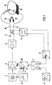
- FIG. 1 An embodiment of a high-frequency surgical device according to the invention, which is equipped with a high-frequency generator that supplies a pure, sinusoidal output voltage U a , is shown in the form of a block diagram in FIG.
- the output of the high-frequency generator consisting of an oscillator 1, an amplifier 2 and an output transformer 3, is routed via a low-pass filter 18, so that only the fundamental frequency of the oscillator 1 is present at the output sockets 10, 11 .
- the automatic regulation of the output voltage U a offers the advantage over known high-frequency surgical devices in which the output voltage is either insufficiently or not automatically regulated that the output voltage U a is automatically monitored in a simple manner and displayed on an electronic display device can. Since the level of the output voltage U a is an important parameter for coagulation and / or cutting processes, it is not only advantageous to regulate this constantly during coagulation and / or cutting processes, but it is reproducible even before the coagulation and / or cutting processes begin and to be able to adjust them sufficiently precisely.
- positive and / or negative deviations can be signaled, the maximum permissible positive and / or negative deviations being able to be defined independently of one another and either triggering only the positive or the negative deviations or triggering both optical 20 and / or acoustic 27 signals.
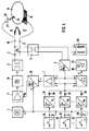
- FIG. 3 Another advantageous embodiment of the in Figure 3 schematically shown high-frequency surgical device offers the equipment with several, Setpoints that can be set independently of one another 22.23 ..., with each setpoint generator over separate buttons 24, 25 ... of an electrode handle or can be activated via separate pedals 24, 25 ... can.
- the individual setpoints can also via buttons on the front panel of the high-frequency surgical device selected and via a finger key activated on the electrode handle or a pedal will.
- FIG. 4 schematically shows a further embodiment of the exemplary embodiment described with reference to FIG. 3 in the form of a block diagram.
- This exemplary embodiment shown in FIG. 4 is equipped with a plurality of setpoint transmitters 22, 23 ... n which can be set independently of one another and which are each activated via separate buttons on the electrode handle and / or pedals 24, 25 ... n. 1 to 3, the setpoint generator may continuously supply a setpoint signal b, in the case of several setpoint generators according to FIG. 4, care must be taken to ensure that the respectively selected setpoint b1 or b2 etc. is only sent to the control amplifier 7 it is delivered how the respective setpoint device 22, 23 ... n is activated by means of buttons or pedal 24, 25 ... n.
- the various setpoint transmitters can also be selected, for example, using buttons on the front panel of the high-frequency surgical device and activated using only one button 26 on the electrode handle 27 or by pedal.
- the outputs of the individual setpoint transmitters are decoupled from one another via diodes 28.
- the activation signal e of the various keys 24, 25 ... n is summarized via the diodes 29.
- the activation signal is supplied not only to the oscillator 1, but also to the electronically controlled power supply unit 16, so that this power supply unit only supplies operating voltage U B when a button or pedal 24, 25 ... n is actuated.
Description
Die Erfindung betrifft ein Hochfrequenz-Chirurgiegerät zum Schneiden und/oder Koagulieren biologischer Gewebe mittels hochfrequenten elektrischen Stromes, mit einem einen Regelverstärker enthaltenden Regelkreis zur automatischen Regelung der Ausgangsspannung des Hochfrequenz-Generators.The invention relates to a high-frequency surgical device for cutting and / or coagulating biological Tissue using high frequency electrical Current, with a one control amplifier containing control loop for automatic control the output voltage of the high frequency generator.
Hochfrequenz-Chirurgiegeräte zum Schneiden und/oder Koagulieren biologischer Gewebe mittels hochfrequenten elektrischen Wechselstromes sind seit über 50 Jahren bekannt und gehören seit vielen Jahren zur Ausrüstung chirurgischer Arbeitsplätze verschiedener chirurgischer Fachbereiche.High frequency surgical equipment for cutting and / or coagulating biological tissue by means of high-frequency electrical alternating current Known for over 50 years and have been owned by many years for equipping surgical workplaces various surgical specialties.
Die Eigenschaften von sowie die Anforderungen an Hochfrequenz-Chirurgiegeräte sind in nationalen und internationalen Normen, insbesondere in DIN/IEC 601 Teil 2-2, Ausgabe Sept. 1984, definiert und festgelegt.The characteristics of as well as the requirements of high-frequency surgical devices are in national and international standards, especially in DIN / IEC 601 Part 2-2, September 1984 edition and fixed.
Wesentlicher Bestandteil aller Hochfrequenz-Chirurgiegeräte sind Hochfrequenzgeneratoren, welche die zum Schneiden und/oder Koagulieren erforderlichen hochfrequenten elektrischen Wechselströme generieren. Um elektrische Reizung von Nerven und Muskeln zu verhindern, soll die Frequenz des Wechselstromes mindestens 300 kHz betragen. Mit Rücksicht auf die Sicherheit des Patienten sowie der Operateure darf die Nenn-Ausgangsleistung von Hochfrequenz-Chirurgiegeräten, gemittelt über eine Sekunde, 400 Watt nicht überschreiten.An essential component of all high-frequency surgical devices are high frequency generators, which are for cutting and / or coagulating required high-frequency electrical alternating currents to generate. To electrical irritation from The frequency is supposed to prevent nerves and muscles of the alternating current at least 300 kHz be. With respect to patient safety as well as the surgeon may use the nominal output power of high-frequency surgical devices, averaged over a second, do not exceed 400 watts.
Je nach Fachbereich und individuellem Anwendungsfall sind zum Schneiden und/oder Koagulieren mehr oder weniger hohe Leistungen erforderlich. Deswegen sind bekannte Hochfrequenz-Chirurgiegeräte mit Einstellelementen für die Ausgangsleistung ausgestattet. Entsprechend DIN/IEC 601 Teil 2-2 müssen Hochfrequenz-Chirurgiegeräte mit Einstellelementen ausgestattet sein, mit denen die Ausgangsleistung auf nicht mehr als 5 % der Nenn-Ausgangsleistung oder auf 10 Watt abgesenkt werden kann, je nachdem, was kleiner ist.Depending on the department and individual application are for cutting and / or coagulating more or less high performance required. That is why known high-frequency surgical devices are with setting elements for the output power fitted. According to DIN / IEC 601 part 2-2 must have high frequency surgical equipment be equipped with setting elements with which the output power to no more than 5% of the Nominal output power or reduced to 10 watts can be, whichever is smaller.
Bei einem bekannten Hochfrequenz-Chirurgiegerät der eingangs genannten Art mit automatischer Regelung der Intensität der elektrischen Lichtbogen zwischen der aktiven Elektrode und dem zu schneidenden oder zu koagulierenden Gewebe, wird zur Feststellung des Ausmaßes der Lichtbogen ein davon abhängiges elektrisches Signal über ein Filter abgeleitet, welches mindestens eine Frequenz der von den elektrischen Lichtbogen erzeugten nichtharmonischen Frequenzen der Grundfrequenz des Hochfrequenz-Oszillators aus der elektrischen Spannung oder aus dem elektrischen Strom im Ausgang durchläßt. Dabei kann abwechselnd ein Sollwertgeber für die Intensität der Schneideleistung oder ein Sollwertgeber für die Intensität der Koagulationsleistung eingeschaltet werden.Ferner wird die Ausgangsleistung des Leistungsverstärkers durch das Ausgangssignal des Regelverstärkers mittels eines Amplitudenmodulators so gesteuert, daß die Intensität der Lichtbogen auf den Sollwert des betreffenden Sollwertgebers geregelt wird (EP-A- 219 568).In a known high-frequency surgical device of the type mentioned at the beginning with automatic Regulation of the intensity of the electrical Arc between the active electrode and the tissue to be cut or coagulated, is used to determine the extent of the Arc an electrical signal dependent on it derived via a filter, which at least a frequency of from the electric arc generated non-harmonic frequencies of the Base frequency of the high-frequency oscillator of the electrical voltage or from the electrical Current passes through. It can alternately a setpoint generator for the intensity the cutting power or a setpoint generator for the Intensity of the coagulation power switched on Furthermore, the output power of the power amplifier by the output signal of the Control amplifier using an amplitude modulator controlled so that the intensity of the arc to the setpoint of the relevant setpoint generator is regulated (EP-A-219 568).
Es ist seit der Einführung der Hochfrequenzchirurgie vor über 50 Jahren bekannt, daß die Leistung, welche Hochfrequenz-Chirurgiegeräte im biologischen Gewebe erzeugen, von verschiedenen Parametern abhängig ist. Die wichtigsten leistungsbestimmenden Parameter sind die Leerlaufspannung und der Innenwiderstand des jeweiligen Hochfrequenzgenerators sowie der elektrische Widerstand des biologischen Gewebes beziehungsweise der Lastwiderstand. Um den Operateuren die Abhängigkeit der vom Hochfrequenz-Chirurgiegerät abgegebenen Leistung vom Lastwiderstand deutlich zu machen, müssen Hersteller von Hochfrequenz-Chirurgiegeräten entsprechend Artikel 6.8.3 DIN/IEC 601 Teil 2-2 in der technischen Beschreibung der Geräte Diagramme angeben, die die abgegebene Leistung bei voller und halber Einstellung des Leistungsstellers über dem Lastwiderstandsbereich von 50 bis 2000 Ohm darstellen, und zwar jeweils für alle Betriebsarten, wie Schneiden, Koagulieren und koagulierender Schnitt. Außerdem müssen auch Diagramme angegeben werden, die die abgegebene Leistung als Funktion der Position des Leistungsstellers für einen anzugebenden Lastwiderstand im Bereich von 50 bis 2000 Ohm für die oben aufgeführten Betriebsarten darstellen.It has been since the advent of radio frequency surgery announced over 50 years ago that performance, which high-frequency surgical devices in produce biological tissues from different Parameters. The main performance determining The parameters are the open circuit voltage and the internal resistance of each High frequency generator as well as the electrical resistance of the biological tissue respectively the load resistance. To the surgeons Dependence on the high-frequency surgical device power output from the load resistance clearly To make, manufacturers of high frequency surgical equipment according to Article 6.8.3 DIN / IEC 601 part 2-2 in the technical description of the devices specify diagrams that the delivered Performance at full and half setting of the power controller over the load resistance range from 50 to 2000 ohms, and for all operating modes, such as cutting, Coagulate and coagulate cut. Furthermore diagrams must also be specified that the output as a function of the position of the power controller for a load resistance to be specified in the range of 50 to 2000 ohms for represent the operating modes listed above.
Dem Operateur helfen die oben genannten Diagramme bestenfalls bei der Auswahl eines für seine spezielle Anwendung geeigneten Hochfrequenz-Chirurgiegerätes. Während der Anwendung, insbesondere wenn dasselbe Hochfrequenz-Chirurgiegeräte für verschiedene Operationen eingesetzt wird, helfen diese Diagramme dem Operateur nicht. Die während des Schneidens und/oder Koagulierens erforderliche Leistung ist nicht, wie oft fälschlich angenommen wird, konstant, sondern von vielen verschiedenen Parametern, wie beispielsweise Tiefe und Geschwindigkeit des Schnittes, Größe der effektiven Kontaktfläche zwischen Koagulationselektrode und Gewebe, Temperatur des koagulierenden Gewebes und physikalische Eigenschaften des zu schneidenden und/oder zu koagulierenden Gewebes, abhängig. In der Praxis ist weder die für den jeweiligen Schneide- und/oder Koagulationsvorgang erforderliche Leistung noch die jeweils vom Hochfrequenz-Chirurgiegerät in jedem Zeitpunkt des Schneide- und/oder Koagulationsvorganges gelieferte Leistung konstant. Dieser Umstand erschwert die Anwendung der Hochfrequenzchirurgie insofern, als die Reproduzierbarkeit der Schneide- und/oder Koagulationseffekte zur Erzielung konstanter Qualität dieser Effekte sehr schwierig ist.The above diagrams help the surgeon at best when choosing one for his Special application of suitable high-frequency surgical device. During use, in particular if the same high frequency surgical equipment is used for various operations, these diagrams do not help the surgeon. The during cutting and / or coagulation required performance is not how often wrong is assumed to be constant, but by many various parameters, such as depth and speed of the cut, size of the effective contact area between the coagulation electrode and tissue, temperature of the coagulating Tissue and physical properties the one to be cut and / or coagulated Tissue, dependent. In practice, neither is for the respective cutting and / or coagulation process required performance still each from the high-frequency surgical device at any time the cutting and / or coagulation process delivered performance constant. This condition complicates the use of high frequency surgery insofar as the reproducibility of the cutting and / or coagulation effects to achieve constant quality of these effects very difficult is.
Trotz dieser Problematik sind seit mehreren Jahren mehr und mehr Hochfrequenz-Chirurgiegeräte bekannt geworden, die mit digitalen Ziffernanzeigen ausgestattet sind, welche Leistungen anzeigen, wobei jedoch nicht die jeweils vom Hochfrequenz-Chirurgiegerät abgegebene Leistung, sondern meistens die theoretisch bei Leistungsanpassung mögliche Leistung angezeigt wird. Eine derartige Anzeige nützt dem Operateur jedoch nicht mehr und nicht weniger als eine dimensionslose Skala am Leistungseinsteller, weswegen DIN/IEC 601 Teil 2-2 diesbezüglich auch vorschreibt, daß der Leistungseinsteller für die Ausgangsleistung mit einer Skala oder Anzeigevorrichtung ausgestattet sein muß, die die abgegebene Hochfrequenzleistung in relativen Einheiten anzeigt. Eine Einteilung der Skala für die Ausgangsleistung in 10 Hauptintervallen wird hierin außerdem empfohlen.Despite this problem, there have been several Years more and more high frequency surgical equipment become known with digital numerical displays are equipped which indicate services, but not each of the high-frequency surgical device output, but mostly the theoretical when adjusting performance possible performance is displayed. Such However, the ad does not benefit the surgeon more and no less than a dimensionless one Scale on the power adjuster, which is why DIN / IEC 601 Part 2-2 in this regard also prescribes that the power adjuster for the output power equipped with a scale or display device must be the high-frequency power output displays in relative units. A division the scale for the output power in 10 main intervals is also recommended herein.
Die Problematik der Leistung bei Hochfrequenz-Chirurgiegeräten wird ausführlich beschrieben in FARIN, G.: Möglichkeiten und Probleme der Standardisierung der Hochfrequenzleistung, in: Hochfrequenzdiathermie in der Endoskopie, herausgegeben von G. Lux und K. Semm, Springer-Verlag, Berlin, Heidelberg, 1987.The performance issue with high frequency surgical equipment is described in detail in FARIN, G .: Possibilities and Problems of Standardization of high frequency power, in: High frequency diathermy in endoscopy, published by G. Lux and K. Semm, Springer-Verlag, Berlin, Heidelberg, 1987.
Da bei konventionellen Hochfrequenz-Chirurgiegeräten eine optimale Übereinstimmung der von Schnitt zu Schnitt beziehungsweise von Koagulation zu Koagulation und auch während jedes einzelnen Schneide- und/oder Koagulationsvorganges erforderlichen Leistung und der vom Gerät gelieferten Leistung fast nie erreicht wird, schwankt die Qualität der Schnitte und/oder Koagulationen mehr oder weniger stark.As with conventional high-frequency surgical devices an optimal match of Cut to cut or coagulation to coagulation and also during each one Cutting and / or coagulation process required Performance and that supplied by the device Performance is almost never achieved, fluctuates Quality of the cuts and / or coagulations more or less strong.
Aus der deutschen Offenlegungsschrift DE 3531576 A ist ein Elektrochirurgiegenerator bekannt, welcher einige der oben dargestellten Probleme dadurch lösen soll, daß die Ausgangsleistung dieses Generators in einem mehr oder weniger großen Lastwiderstandsbereich automatisch auf eine einstellbare Sollausgangsleistung konstant geregelt wird. Diese Lösung widerspricht der praktischen Erfahrung, daß die während Schneide- und/oder Koagulationsvorgängen erforderliche Leistung nicht konstant, sondern von verschiedenen, bereits oben aufgeführten Parametern abhängig ist.From the German published application DE 3531576 A an electrosurgery generator is known which are some of the problems outlined above should solve that the output power this generator in a more or less wide load resistance range automatically an adjustable target output power is constantly regulated becomes. This solution contradicts the practical one Experience that during cutting and / or Coagulation operations required performance not constant, but of different, already depends on the parameters listed above.
Aus dieser Problematik resultiert zusätzlich das Problem, daß eine automatische Überwachung, ob das Hochfrequenz-Chirurgiegerät mehr oder weniger Leistung liefert, als für den jeweiligen Zweck erforderlich, nicht möglich ist. Das hat in der Praxis zur Folge, daß mehr Gewebe thermisch geschädigt wird als notwendig, oder daß der gewünschte Effekt ausbleibt. Bei kritischen Operationen, wie beispielsweise im Bereich der operativen Endoskopie, kann dies, wie die Erfahrung zeigt, zu schweren Komplikationen führen.This also results from this problem Problem that automatic monitoring whether the high-frequency surgical device more or less Performance delivers than for the purpose required, is not possible. That has in practice as a result, more tissue is thermally damaged is considered necessary or that the desired effect is absent. For critical operations such as in the field of operative endoscopy, As experience shows, this can be too serious Complications.
Aus der amerikanischen Patentschrift US 4,092,986 ist ein Hochfrequenz-Chirurgiegerät bekannt, bei welchem ein Rückkoppelungskreis vom Ausgang zum Eingang des Oszillators vorhanden ist, um die gewählte Ausgangsspannung unabhängig vom Lastwiderstand auf einen konstanten Pegel zu halten. Hierfür wird ein automatischer Regelkreis in an sich bekannter Wirkungsweise vorgestellt, bestehend aus einem Generator, dessen Istwert der Ausgangsspannung mittels eines Detektors ermittelt und mit einem Sollwert verglichen wird, wobei Abweichungen des Istwertes vom Sollwert so auf den Generator einwirken, daß diese Abweichung möglichst klein ist.From the American patent specification US 4,092,986 a high-frequency surgical device is known in which a feedback loop from Output to the input of the oscillator available is independent of the selected output voltage from the load resistance to a constant level to keep. For this an automatic control loop presented in a manner known per se, consisting of a generator, its actual value the output voltage is determined by means of a detector and compared to a target value, where Deviations of the actual value from the target value see above act on the generator that this deviation is as small as possible.
Diese Aufgabe wird mit der in US-A-4 092 986 beschriebenen Einrichtung jedoch nur unzureichend gelöst. Der Detektor, welcher den Istwert der Ausgangsspannung ermitteln soll, besteht aus einer Spule 132, welche an den magnetischen Kreis 34 des Resonanzkreises des Oszillators angekoppelt ist. Eine Proportionalität zwischen der Ausgangsspannung des Generators an den Ausgangsbuchsen 122 und dem Ausgangssignal dieses Detektors ist insofern nur unzureichend vorhanden, als der Spannungsabfall an dem bei Hochfrequenz-Chirurgiegeräten allgemein üblichen Kondensator 118 im Anwendungsstromkreis, welcher niederfrequente Ströme und die hierdurch möglichen Reizungen von Nerven und Muskeln verhindern soll und welcher nach der internationalen Norm IEC 601 Teil 2-2 nicht größer als 5000 pF sein darf, nicht berücksichtigt wird. Ein derartiger Kondensator hat beispielsweise bei 500 kHz 63,7 Ohm und bei 300 kHz beispielsweise 106 Ohm Widerstand.This task is accomplished with that in US-A-4 092 986 described facility, however, is insufficient solved. The detector, which is the actual value of the Should determine output voltage consists of a Coil 132, which is connected to the magnetic circuit 34 of the resonant circuit of the oscillator coupled is. A proportionality between the output voltage of the generator at the output sockets 122 and the output of this detector is inadequate in that the Voltage drop at that in high-frequency surgical devices common capacitor 118 im Application circuit, which low-frequency Currents and the possible irritation of nerves and muscles and which one according to the international standard IEC 601 part 2-2 must not be greater than 5000 pF, not taken into account becomes. Such a capacitor has, for example at 500 kHz 63.7 ohms and at 300 kHz, for example 106 ohm resistance.
Da bei Schneide- und Koagulationsvorgängen Stromstärken von einigen mA bis zu etwa 2000 mA vorkommen, ergeben sich Schwankungen der Ausgangsspannung bis zu etwa 200 Volt. Bei speziellen Anwendungen, bei denen, wenn auch kurzzeitig, noch größere Stromstärken entstehen, schwankt die Ausgangsspannung entsprechend stärker. Hierdurch wird die gewünschte Reproduzierbarkeit der Schneide- und/oder Koagulationsqualität nicht erreicht.As with cutting and coagulation processes Current strengths from a few mA up to about 2000 mA fluctuations in the output voltage occur up to about 200 volts. With special Applications in which, albeit briefly, even greater currents arise the output voltage fluctuates accordingly stronger. This makes the desired reproducibility the cutting and / or coagulation quality not reached.
Es ist Aufgabe der Erfindung, Hochfrequenz-Chirurgiegeräte derart zu gestalten, daß die automatische Regelung der HF-Ausgangsspannung im Vergleich zu der aus US-A-4 092 986 bekannten Regeleinrichtung verbessert wird. Ferner sollen die oben aufgeführten Parameter, welche die für Schneide- und/oder Koagulationsvorgänge erforderliche Leistung beeinflussen, weitestgehend automatisch berücksichtigt werden, so daß die Qualität der Schnitte sowie der Koagulationen unabhängig wird von dieses Parametern. Ferner soll ermöglicht werden, die Hochfrequenz-Chirurgiegeräte mit Anzeigeeinrichtungen auszustatten, welche dem Operateur vor und während des Schneidens und/oder Koagulierens zuverlässig relevante, vom Hochfrequenz-Chirurgiegerät bestimmte Parameter anzeigen, die mit der Qualität des Schnittes und/oder der Koagulation korrelieren. Ferner soll ermöglicht werden, die Hochfrequenz-Chirurgiegeräte mit Sicherheitseinrichtungen auszustatten, welche die Einhaltung der für Schneide- und/oder Koagulagionsvorgänge relevanten Parameter überwachen und Abweichungen von Sollwerten dieser Parameter signalisieren.It is an object of the invention to high-frequency surgical devices in such a way that the automatic Regulation of the HF output voltage in the Comparison to that known from US-A-4 092 986 Control device is improved. Furthermore, the parameters listed above, which are the for Cutting and / or coagulation processes required Influence performance, largely automatically be taken into account so that the quality of the Cuts as well as the coagulation becomes independent of this parameter. It should also enable the high-frequency surgical devices with display devices equip which the surgeon before and during cutting and / or Coagulate reliably relevant, from the high frequency surgical device display certain parameters, with the quality of the cut and / or correlate the coagulation. It should also allow high-frequency surgical devices with safety devices equip which the Compliance with the requirements for cutting and / or coagulation processes monitor relevant parameters and deviations from target values of these parameters signal.
Diese Aufgabe wird erfindungsgemäß durch den Gegenstand des Patentanspruches 1 gelöst. Vorteilhafte Weiterbildungen der Erfindung sind Gegenstand der abhängigen Ansprüche.This object is achieved by solved the subject of claim 1. Advantageous developments of the invention are Subject of the dependent claims.
Die Erfindung geht von der Erkenntnis aus, daß zum Schneiden und/oder Koagulieren biologischer Gewebe mittels hochfrequenten elektrischen Wechselstromes zwar Leistung erforderlich, die hierfür erforderliche, von Schnitt zu Schnitt, von Koagulation zu Koagulation und während jedes Schneide- und/oder Koagulationsvorganges mehr oder weniger schwankende Leistung jedoch bei konventionellen Hochfrequenz-Chirurgiegeräten weder optimal voreingestellt noch während einzelner Schneide- und/oder Koagulationsvorgänge optimal dem zu jedem Zeitpunkt bestehenden Leistungsbedarf entsprechend geliefert werden kann.The invention is based on the knowledge that for cutting and / or coagulating biological Tissue using high-frequency electrical alternating current although performance is required for this required, from cut to cut, from coagulation for coagulation and during each cutting and / or Coagulation process more or less fluctuating performance with conventional High frequency surgical equipment is neither optimal preset during individual cutting and / or Coagulation processes optimally to everyone Corresponding time to existing power requirements can be delivered.
Die oben aufgeführten Probleme, welche aus der Diskrepanz zwischen für Schneide- und/oder Koagulationsvorgänge erforderlichen und der von konventionellen Hochfrequenz-Chirurgiegeräten gelieferten Leistung resultieren, werden bei dem erfindungsgemäßen Hochfrequenz-Chirurgiegerät vermieden, indem bei diesem Gerät nicht die Leistung, sondern die Ausgangsspannung als Kriterium für Schneide- und/oder Koagulationseffekte eingestellt kontrolliert und angezeigt wird. Voraussetzung hierfür ist jedoch, daß die Ausgangsspannung des Hochfrequenz-Chirurgiegerätes für Schneide- und/oder Koagulationsvorgänge definitiv eingestellt werden kann und daß die eingestellte Ausgangsspannung bei allen relevanten Lastwiderständen automatisch und ausreichend schnell auf den eingestellten Pegel geregelt wird.The problems listed above, which from the discrepancy between for cutting and / or Coagulation processes required and that of conventional high frequency surgical equipment Performance will result in the invention High-frequency surgical device avoided, by not giving the performance, but the output voltage as a criterion set for cutting and / or coagulation effects checked and displayed. requirement for this, however, is that the output voltage the high-frequency surgical device for cutting and / or Coagulation processes definitely stopped can and that the set output voltage with all relevant load resistances automatically and sufficiently quickly to the set Level is regulated.
Die Erfindung geht außerdem von der Erkenntnis aus, daß zum Schneiden biologischer Gewebe mittels hochfrequenten elektrischen Wechselstromes eine Mindestspannung von etwa 150 Veff erforderlich ist, um die zum Zünden und Aufrechterhalten elektrischer Lichtbogen zwischen Schneideelektrode und Gewebe erforderliche elektrische Feldstärke zu erreichen. Wichtig in diesem Zusammenhang ist auch die Beobachtung, daß bereits geringe Erhöhungen der Ausgangsspannung über die Mindestspannung hinaus deutlich die Schnittqualität ändern, und zwar in der Weise, daß die Intensität der elektrischen Lichtbogen deutlich größer wird und damit auch der Koagulationsgrad der Schnittflächen während des Schneidens. Wichtig in diesem Zusammenhang ist insbesondere auch die Beobachtung, daß die Schnittqualität weitgehend unabhängig von der Schnittgeschwindigkeit und Tiefe des Schnittes wird, wenn die Ausgangsspannung konstant gehalten wird. Bei Koagulationen mit typischen Koagulationselektroden, wie beispielsweise Kugel- oder Plattenelektroden, konnte beobachtet werden, daß die Koagulationsvorgänge und Koagulationsqualität weitgehend unabhängig von der Kontaktfläche zwischen der jeweiligen Koagulationselektrode und dem biologischen Gewebe ist, wenn die Ausgangsspannung konstant gehalten wird. Aber auch hierbei ergeben bereits Änderungen der Ausgangsspannung Infolge der physikalischen Gesetzmäßigkeit, daß die Leistung dem Quadrat der Spannung proportional ist, relativ große Änderungen der Koagulationsqualität.The invention is also based on the knowledge that a minimum voltage of approximately 150 V rms is required for cutting biological tissue by means of high-frequency electrical alternating current in order to achieve the electrical field strength required to ignite and maintain electrical arcs between the cutting electrode and tissue. It is also important in this connection to observe that even small increases in the output voltage above the minimum voltage change the cut quality significantly, in such a way that the intensity of the electric arcs becomes significantly greater and thus also the degree of coagulation of the cut surfaces during the cutting. It is particularly important in this context to observe that the cutting quality becomes largely independent of the cutting speed and depth of the cut if the output voltage is kept constant. In coagulation with typical coagulation electrodes, such as spherical or plate electrodes, it was observed that the coagulation processes and coagulation quality are largely independent of the contact area between the respective coagulation electrode and the biological tissue if the output voltage is kept constant. But even here changes in the output voltage already result in relatively large changes in the coagulation quality due to the physical law that the power is proportional to the square of the voltage.
Die erfindungsgemäße Lösung der oben genannten Aufgabe unterscheidet sich von der oben zitierten bekannten Lösung dadurch, daß die Ausgangsspannung direkt an den Ausgangsbuchsen automatisch kontrolliert und automatisch auf den an einem Sollwertgeber einstellbaren Pegel geregelt wird. Noch besser wäre die Kontrolle und automatische Regelung der elektrischen Spannung direkt zwischen der aktiven Elektrode und der neutralen Elektrode oder gar dem biologischen Gewebe in der Nähe der Schneide- und/oder Koagulationsvorgänge bzw. direkt an den Polen von bipolaren Elektroden.The inventive solution to the above object differs from that Known solution cited above in that the output voltage directly to the Output sockets are automatically checked and automatically connected to a setpoint device adjustable level is regulated. Control and automatic would be even better Regulation of the electrical voltage directly between the active electrode and the neutral electrode or even the biological tissue near the cutting and / or Coagulation processes or directly on the poles of bipolar electrodes.
Die Erfindung berücksichtigt insbesondere das Problem, daß eine definitive Spannungsregelung nur dann möglich ist, wenn die Form der Spannung bzw. deren Anteil harmonischer und/oder nichtharmonischer Frequenzen während aller relevanten Betriebsbedingungen konstant bleibt, da andernfalls das Verhältnis von Spitzenwert zu Effektivwert oder Effektivwert zu einem beliebigen Mttelwert der Spannung nicht konstant wäre. Das erfindungsgemäße Hochfrequenz-Chirurgiegerät kann deswegen weiter verbessert werden, indem es mit einem Hochfrequenzgenerator ausgestattet wird, der eine von allen relevanten Betriebsbedingungen unabhängige konstante Spannungsform, vorzugsweise eine reine Sinusform, erzeugt.The invention particularly takes into account the problem of definitive voltage regulation is only possible if the shape of the voltage or its proportion is more harmonious and / or non-harmonic frequencies during all relevant operating conditions remains constant, otherwise the ratio of peak value to effective value or the RMS value would not be constant at any mean value of the voltage. The high-frequency surgical device according to the invention can therefore be further improved by equipping it with a high frequency generator that is one of constant voltage form independent of all relevant operating conditions, preferably a pure sinusoidal shape.
Das erfindungsgemäße Hochfrequenz-Chirurgiegerät bietet nicht nur den Vorteil reproduzierbarer und konstanter Qualität von Schneide- und/oder Koagulationsvorgängen, sondern darüber hinaus auch den Vorteil, daß die Ausgangsspannung vor und während Schneide- und/oder Koagulationsvorgängen automatisch kontrolliert und auf einer elektronischen Anzeigeeinrichtung angezeigt werden. So werden der Istwert der Ausgangsspannung mit dem Sollwert der Ausgangsspannung automatisch verglichen und bei beliebig wählbaren Toleranzgrenzen optische und/oder akustische Signale erzeugt sobald die gewählten Toleranzgrenzen überschritten sind. Ein Über-oder Unterschreiten beliebig wählbarer Toleranzgrenzen der Abweichung des Istwertes vom Sollwert der Ausgangsspanng kann auch zur automatischen Abschaltung der Hochfrequenzgenerators verwendet werden. Die Anzeige des Istwertes und/oder des Sollwertes der Ausgangsspannung ermöglicht sowohl eine Voreinstellung der Ausgangsspannung vor dem Einsatz des Gerätes zum Schneiden und/oder Koagulieren als auch eine Kontrolle der Ausgangsspannung während Schneide- und/oder Koagulationsvorgängen. The high-frequency surgical device according to the invention not only offers the advantage of being reproducible and constant quality of cutting and / or coagulation processes, but also the advantage that the output voltage before and during Cutting and / or coagulation processes automatically controlled and on an electronic Display device can be displayed. So the actual value of the output voltage automatically compared with the target value of the output voltage and generates optical and / or acoustic signals at any selectable tolerance limits as soon as the selected tolerance limits are exceeded. An over or Falling below any selectable tolerance limits for the deviation of the actual value from the setpoint the output voltage can also be used to automatically switch off the high-frequency generator be used. The display of the actual value and / or the setpoint the output voltage allows both a pre-setting of the output voltage the use of the device for cutting and / or coagulating as well as a control the output voltage during cutting and / or coagulation processes.
In weiterer Ausgestaltung der Erfindung können Hochfrequenz-Chirurgiegeräte mit mehreren Sollwertgebern ausgestattet werden, welche verschiedene Sollwerte liefern. Auf diese Weise können verschiedene Schneide- und/oder Koagulationsqualitäten vorprogrammiert und je nach Bedarf über verschiedene Tasten am Elektrodengriff, verschiedene Pedale oder beispielsweise über Tasten auf der Frontplatte des Hochfrequenz-Chirurgiegerätes abgerufen werden. Für diese Ausgestaltung bieten integrierte Halbleiterschaltungen und Mikroprozessoren einfach realisierbare Möglichkeiten.In a further embodiment of the invention High frequency surgical devices with multiple Setpoint sensors, which are different Deliver setpoints. That way you can different cutting and / or coagulation qualities preprogrammed and as required via different buttons on the electrode handle, different Pedals or buttons, for example on the front panel of the high-frequency surgical device be retrieved. For this configuration offer semiconductor integrated circuits and microprocessors easy to implement options.
Anhand schematischer Zeichnungen wird das
erfindungsgemäße Hochfrequenz-Chirurgiegerät
näher beschrieben. Es zeigen:
Der Trenntransformator 5 ist erforderlich um
eine ausreichende elektrische Isolationsstrecke zwischen
Anwendungsstromkreis 17 sowie interner
Betriebsspannungen des Hochfrequenz-Chirurgiegerätes
einerseits und Erdpotential andererseits zu
gewährleisten.The isolating
Diese erforderliche elektrische Isolation kann jedoch auch mit anderen Bauelementen, wie beispielsweise mittels Optokopplern, realisiert werden, wobei beispielsweise eine Glühbirne an die Ausgangsspannung Ua angeschlossen wird und deren Licht beispielsweise einem Fotoelement, einem Fototransistor oder einem Fotowiderstand zugeführt wird, so daß Helligkeitsschwankungen der Glühbirne infolge Schwankungen der Ausgagngsspannung Ua zu proportionalen elektrischen Signalen am Fotoelement, Fototransistor oder Fotowiderstand führen. Ein derartiger Spannungswandler würde ein dem Effektivwert von Ua proportionales elektrisches Signal liefern.However, this required electrical insulation can also be realized with other components, such as by means of optocouplers, for example, a light bulb being connected to the output voltage U a and the light of which is supplied, for example, to a photo element, a photo transistor or a photo resistor, so that brightness fluctuations in the light bulb lead to proportional electrical signals at the photo element, photo transistor or photo resistor due to fluctuations in the output voltage U a . Such a voltage converter would deliver an electrical signal proportional to the effective value of U a .
Das elektrische Signal
Die Rückkopplung eines der Ausgangsspannung
Ua an den Ausgangsbuchsen 10, 11 des
Hochfrequenz-Chirurgiegerätes proportionalen Signales
Der Vollständigkeit halber sind in Figur 1 auch
ein Oszillator 1, welcher mittels eines Tasters oder
Pedals 9 aktiviert wird, sowie schematisch biologisches
Gewebe 14 sowie eine aktive 13 und eine
neutrale Elektrode 15 und alternativ eine bipolare
Elektrode 12 dargestellt.
Konventionelle Hochfrequenz-Chirurgiegeräte sind
in der Regel mit Hochfrequenzgeneratoren ausgestattet,
welche mit Rücksicht auf einen möglichst
hohen Wirkungsgrad Endverstärker haben,die in
Schalterbetrieb betrieben werden, so daß die Form
der Ausgangsspannung Ua mehr oder weniger von
einer reinen Sinusform abweicht. Wenn diese Abweichung
von der reinen Sinusform außerdem auch
noch von der Betriebsbedingung des Hochfrequenz-Chirurgiegerätes
abhängig ist, wird die Definition
der Proportionalität des elektrischen Signales
Conventional high-frequency surgical devices are usually equipped with high-frequency generators, which have power amplifiers in consideration of the highest possible efficiency, which are operated in switch mode, so that the shape of the output voltage U a deviates more or less from a pure sinusoidal shape. If this deviation from the pure sinus shape is also dependent on the operating condition of the high-frequency surgical device, the definition of the proportionality of the electrical signal
Die Abhängigkeit der Proportionalität des elektrischen
Signales a von der Form der Ausgangsspannung
Ua kann vermieden werden, indem ein
Hochfrequenzgenerator verwendet wird, der bei allen
relevanten Betriebsbedingungen eine sinusförmige
Ausgangsspannung Ua an die Ausgangsbuchsen
10, 11 liefert, also frei ist von harmonischen
und/oder nichtharmonischen Frequenzen der
Grundfrequenz. Eine vorteilhafte Ausgestaltung des
erfindungsgemäßen Hochfrequenz-Chirurgiegerätes
stellt daher die Kombination mit einem Hochfrequenzgenerator
dar, welcher möglichst nur die
Grundfrequenz, also möglichst keine harmonischen
und/oder nichtharmonischen Frequenzen der
Grundfrequenz erzeugt.
Ein Ausführungsbeispiel eines erfindungsgemäßen
Hochfrequenz-Chirurgiegerätes, welches mit einem
Hochfrequenzgenerator ausgestattet ist, der eine
reine , sinusförmige Ausgangsspannung Ua liefert,
ist in Form eines Blockschaltbildes in Figur 2 dargestellt.
Zusätzlich zu allen aus Figur 1 bekannten
Elementen ist der Ausgang des Hochfrequenzgenerators,
bestehend aus einem Oszillator 1, einem
Verstärker 2 und einem Ausgangstransformator 3,
über ein Tiefpaßfilter 18 geführt, so daß an den
Ausgangsbuchsen 10, 11 nur die Grundfrequenz
des Oszillators 1 vorhanden ist.The dependence of the proportionality of the electrical signal a on the shape of the output voltage U a can be avoided by using a high-frequency generator which supplies a sinusoidal output voltage U a to the
An embodiment of a high-frequency surgical device according to the invention, which is equipped with a high-frequency generator that supplies a pure, sinusoidal output voltage U a , is shown in the form of a block diagram in FIG. In addition to all the elements known from FIG. 1, the output of the high-frequency generator, consisting of an oscillator 1, an
Die automatische Regelung der Ausgangsspannung Ua bietet im Vergleich zu bekannten Hochfrequenz-Chirurgiegeräten, bei denen die Ausgangsspannung entweder nur ungenügend oder gar nicht automatisch geregelt ist, den Vorteil, daß die Ausgangsspannung Ua in einfacher Weise automatisch überwacht und auf einer elektronischen Anzeigeeinrichtung angezeigt werden kann. Da die Höhe der Ausgangsspannung Ua ein wichtiger Parameter für Koagulations- und/oder Schneidevorgänge ist, ist es nicht nur vorteilhaft, diese während Koagulations- und/oder Schneidevorgängen konstant zu regeln, sondern diese bereits vor Beginn der Koagulations- und/oder Schneidevorgänge reproduzierbar und ausreichend genau einstellen zu können.The automatic regulation of the output voltage U a offers the advantage over known high-frequency surgical devices in which the output voltage is either insufficiently or not automatically regulated that the output voltage U a is automatically monitored in a simple manner and displayed on an electronic display device can. Since the level of the output voltage U a is an important parameter for coagulation and / or cutting processes, it is not only advantageous to regulate this constantly during coagulation and / or cutting processes, but it is reproducible even before the coagulation and / or cutting processes begin and to be able to adjust them sufficiently precisely.
In Figur 3 ist eine diesbezüglich weitere Ausgestaltung
des in Figur 2 schematisch dargestellten
Hochfrequenz-Chirurgiegerätes ebenfall in Form eines
Blockschaltbildes dargestellt. Da das elektrische
Signal
Außerdem kann das Signal a und/oder das
Signal b auf elektronischen Anzeigeeinrichtungen
26, beispielsweise mittels sogenannter Bar Graphen,
angezeigt werden.In addition, the signal a and / or that
Signal b on
Eine weitere vorteilhafte Ausgestaltung des in
Figur 3 schematisch dargestellten Hochfrequenz-Chirurgiegerätes
bietet die Ausstattung mit mehreren,
voneinander unabhängig einstellbaren Sollwertgebern
22,23..., wobei jeder Sollwertgeber über
separate Tasten 24,25... eines Elektrodengriffes
oder über separate Pedale 24,25... aktivierbar sein
kann. Die einzelnen Sollwertgeber können auch
über Tasten auf der Frontplatte des Hochfrequenz-Chirurgiegerätes
angewählt und über eine Fingertaste
am Elektrodengriff oder einem Pedal aktiviert
werden.Another advantageous embodiment of the in
Figure 3 schematically shown high-frequency surgical device
offers the equipment with several,
Setpoints that can be set independently of one another
22.23 ..., with each setpoint generator over
In Figur 4 ist diesbezüglich eine weitere Ausgestaltung
des anhand von Fig. 3 beschriebenen
Ausführungsbeispieles in Form eines Blockschaltbildes
schematisch dargestellt. Dieses in Fig. 4
dargestellte Ausführungsbeispiel ist mit mehreren
voneinander unabhängig einstellbaren Sollwertgebern
22, 23 ... n ausgestattet, welche jeweils über
separate Tasten am Elektrodengriff und/oder Pedale
24, 25 ... n aktiviert werden. Während bei den
vorhergehenden Ausführungsbeispielen entsprechend
Fig. 1 bis Fig. 3 der Sollwertgeber ständig
ein Sollwertsignal b liefern darf, muß bei mehreren
Sollwertgebern entsprechend Fig. 4 darauf geachtet
werden, daß der jeweils gewählte Sollwert b1
oder b2 usw. nur solange an den Regelverstärker 7
geliefert wird, wie der jeweilige Sollwertgeber 22,
23 ... n mittels Tasten oder Pedal 24, 25 ... n
aktiviert ist. Die verschiedenen Sollwertgeber können
jedoch beispielsweise auch per Tasten auf der
Frontplatte des Hochfrequenz-Chirurgiegerätes angewählt
und mittels nur einer Taste 26 am Elektrodengriff
27 oder per Pedal aktiviert werden. Die
Ausgänge der einzelnen Sollwertgeber sind über
Dioden 28 gegeneinander entkoppelt. Das Aktivierungssignal
e der verschiedenen Tasten 24, 25 ... n
wird über die Dioden 29 zusammengefaßt. Das
Aktivierungssignal wird nicht nur dem Oszillator 1,
sondern auch dem elektronisch gesteuerten Netzteil
16 zugeführt, so daß dieses Netzteil nur dann
Betriebsspannung UB liefert, wenn eine Taste bzw.
Pedal 24, 25 ... n betätigt ist.In this regard, FIG. 4 schematically shows a further embodiment of the exemplary embodiment described with reference to FIG. 3 in the form of a block diagram. This exemplary embodiment shown in FIG. 4 is equipped with a plurality of
Bezüglich des Einschwingverhaltens aller Ausführungsbeispiele
beim Aktivieren des Hochfrequenzgenerators
ist je nach Regelzeitkonstante des
Regelkreises darauf zu achten, daß in dem Zeitpunkt,
in dem das Sollwertsignal b über den Regelverstärker
7 auf den Verstärker 2 oder auf das
elektronisch gesteuerte Netzteil 16 einwirkt, während
das Signal a noch nicht am Regelverstärker
anliegt, die Ausgangsspannung Ua nicht, wenn
auch nur sehr kurzzeitig, unakzeptabel über den
gewünschten Sollwert ansteigt. Deswegen ist es
beispielsweise zweckmäßig, das elektronisch gesteuerte
Netzteil so zu dimensionieren, daß die
Anstiegsflanke der Betriebsspannung UB nicht zu
steil ist, sondern mit der Regelzeitkonstante des
Regelkreises so abgestimmt ist, daß UB so ansteigt,
daß Ua im Einschaltmoment infolge Regelverzögerung
nicht unakzeptabel hoch ansteigen
kann.Regarding the transient response of all exemplary embodiments when activating the high-frequency generator, depending on the control time constant of the control loop, care should be taken to ensure that at the point in time at which the setpoint signal b acts on the
Claims (9)
- A high-frequency surgical instrument for the cutting and/or coagulating of biological tissue by means of high-frequency (HF) electric current, with a HF generator containing an oscillator (1), an amplifier (2) and an output transformer (3), and also with a regulating circuit containing a nominal value setter (8),to produce a nominal value signal (b), and a regulating amplifier (7), for the automatic regulation of the output voltage of the HF generator, characterised in that at the output sockets (10,11) for the application current circuit (17) or points (12,13,14,15) of the application current circuit (17) lying closer to the electrodes, a voltage transducer (6) combined with an electric isolation (5) is connected, the output signal of which is supplied as actual value signal (
and that signals corresponding to the
nominal value signal (b) and the actual value signal (a) are able to be supplied to a voltage comparator (19), after which a display arrangement (20,21) is connected, in order to produce an optical signal and/or an acoustic signal when predetermined tolerance thresholds of the difference (d) of the nominal value signal (b) and of the actual value signal (a) are exceeded or are fallen below, for supporting the operator. - A high-frequency surgical instrument according to Claim 1, characterised in that the electric isolation is provided in the form of an isolating transformer (5) or of an opto-coupler.
- A high-frequency surgical instrument according to one of the preceding claims, characterised in that the high-frequency generator (1,2,3) is equipped with a low-pass filter (18), so that it delivers a pure sinusoidal voltage (Ua) to the output sockets (10,11).
- A high-frequency surgical instrument according to one of the preceding claims, characterised in that several nominal value setters (22,23 ...n), able to be adjusted independently of each other, are present, which can be activated independently of each other by means of keys on the electrode grip (27) and/or pedals (24,25... n).
- A high-frequency surgical instrument according to Claim 1, characterised in that the voltage converter (6) is constructed such that it delivers an electrical signal (a) proportional to the peak value of the output voltage (Ua).
- A high-frequency surgical instrument according to Claim 1, characterised in that the voltage converter (6) is constructed such that it delivers an electrical signal (a) proportional to the effective value of the output voltage (Ua).
- A high-frequency surgical instrument according to Claim 1, characterised in that the voltage converter (6) is constructed such that it delivers an electrical signal (a) proportional to a mean value of the output voltage (Ua).
- A high-frequency surgical instrument according to Claim 4, characterised in that the nominal value setters (22,23... n), which are adjustable independently of each other, are able to be selected by means of keys on the exterior of the high-frequency surgical instrument.
- A high-frequency surgical instrument according to one of the preceding claims, characterised in that a high-frequency generator (1,2,3,18) is provided, which only produces the fundamental frequency without harmonic and/or non-harmonic frequencies of the fundamental frequency.
Priority Applications (4)
| Application Number | Priority Date | Filing Date | Title |
|---|---|---|---|
| EP87116954A EP0316469B2 (en) | 1987-11-17 | 1987-11-17 | High frequence surgical device to cut and/or coagulate biological tissues |
| EP95100278A EP0653192B1 (en) | 1987-11-17 | 1987-11-17 | High frequence surgical device to cut and/or coagulate biological tissues |
| DE3751452T DE3751452D1 (en) | 1987-11-17 | 1987-11-17 | High-frequency surgical device for cutting and / or coagulating biological tissue. |
| US07/477,117 US4969885A (en) | 1987-11-17 | 1990-02-07 | High frequency surgery device for cutting and/or coagulating biologic tissue |
Applications Claiming Priority (1)
| Application Number | Priority Date | Filing Date | Title |
|---|---|---|---|
| EP87116954A EP0316469B2 (en) | 1987-11-17 | 1987-11-17 | High frequence surgical device to cut and/or coagulate biological tissues |
Related Child Applications (2)
| Application Number | Title | Priority Date | Filing Date |
|---|---|---|---|
| EP95100278A Division EP0653192B1 (en) | 1987-11-17 | 1987-11-17 | High frequence surgical device to cut and/or coagulate biological tissues |
| EP95100278.1 Division-Into | 1987-11-17 |
Publications (3)
| Publication Number | Publication Date |
|---|---|
| EP0316469A1 EP0316469A1 (en) | 1989-05-24 |
| EP0316469B1 EP0316469B1 (en) | 1995-08-09 |
| EP0316469B2 true EP0316469B2 (en) | 1998-11-25 |
Family
ID=8197452
Family Applications (2)
| Application Number | Title | Priority Date | Filing Date |
|---|---|---|---|
| EP87116954A Expired - Lifetime EP0316469B2 (en) | 1987-11-17 | 1987-11-17 | High frequence surgical device to cut and/or coagulate biological tissues |
| EP95100278A Expired - Lifetime EP0653192B1 (en) | 1987-11-17 | 1987-11-17 | High frequence surgical device to cut and/or coagulate biological tissues |
Family Applications After (1)
| Application Number | Title | Priority Date | Filing Date |
|---|---|---|---|
| EP95100278A Expired - Lifetime EP0653192B1 (en) | 1987-11-17 | 1987-11-17 | High frequence surgical device to cut and/or coagulate biological tissues |
Country Status (3)
| Country | Link |
|---|---|
| US (1) | US4969885A (en) |
| EP (2) | EP0316469B2 (en) |
| DE (1) | DE3751452D1 (en) |
Cited By (11)
| Publication number | Priority date | Publication date | Assignee | Title |
|---|---|---|---|---|
| US5944715A (en) | 1996-06-20 | 1999-08-31 | Gyrus Medical Limited | Electrosurgical instrument |
| US6004319A (en) | 1995-06-23 | 1999-12-21 | Gyrus Medical Limited | Electrosurgical instrument |
| US6013076A (en) | 1996-01-09 | 2000-01-11 | Gyrus Medical Limited | Electrosurgical instrument |
| US6015406A (en) | 1996-01-09 | 2000-01-18 | Gyrus Medical Limited | Electrosurgical instrument |
| US6027501A (en) | 1995-06-23 | 2000-02-22 | Gyrus Medical Limited | Electrosurgical instrument |
| US6090106A (en) | 1996-01-09 | 2000-07-18 | Gyrus Medical Limited | Electrosurgical instrument |
| US6093186A (en) | 1996-12-20 | 2000-07-25 | Gyrus Medical Limited | Electrosurgical generator and system |
| US6210405B1 (en) | 1996-06-20 | 2001-04-03 | Gyrus Medical Limited | Under water treatment |
| US6261286B1 (en) | 1995-06-23 | 2001-07-17 | Gyrus Medical Limited | Electrosurgical generator and system |
| US6277114B1 (en) | 1998-04-03 | 2001-08-21 | Gyrus Medical Limited | Electrode assembly for an electrosurical instrument |
| US6565561B1 (en) | 1996-06-20 | 2003-05-20 | Cyrus Medical Limited | Electrosurgical instrument |
Families Citing this family (176)
| Publication number | Priority date | Publication date | Assignee | Title |
|---|---|---|---|---|
| DE3911416A1 (en) * | 1989-04-07 | 1990-10-11 | Delma Elektro Med App | ELECTRO-SURGICAL HIGH-FREQUENCY DEVICE |
| DE4009819C2 (en) * | 1990-03-27 | 1994-10-06 | Siemens Ag | HF surgery device |
| US5279547A (en) * | 1991-01-03 | 1994-01-18 | Alcon Surgical Inc. | Computer controlled smart phacoemulsification method and apparatus |
| US5160317A (en) * | 1991-01-03 | 1992-11-03 | Costin John A | Computer controlled smart phacoemulsification method and apparatus |
| US5633578A (en) * | 1991-06-07 | 1997-05-27 | Hemostatic Surgery Corporation | Electrosurgical generator adaptors |
| US5330471A (en) * | 1991-06-07 | 1994-07-19 | Hemostatic Surgery Corporation | Bi-polar electrosurgical endoscopic instruments and methods of use |
| US5472443A (en) * | 1991-06-07 | 1995-12-05 | Hemostatic Surgery Corporation | Electrosurgical apparatus employing constant voltage and methods of use |
| US5484436A (en) * | 1991-06-07 | 1996-01-16 | Hemostatic Surgery Corporation | Bi-polar electrosurgical instruments and methods of making |
| US5207691A (en) * | 1991-11-01 | 1993-05-04 | Medical Scientific, Inc. | Electrosurgical clip applicator |
| US5713896A (en) * | 1991-11-01 | 1998-02-03 | Medical Scientific, Inc. | Impedance feedback electrosurgical system |
| US5902272A (en) * | 1992-01-07 | 1999-05-11 | Arthrocare Corporation | Planar ablation probe and method for electrosurgical cutting and ablation |
| US5683366A (en) * | 1992-01-07 | 1997-11-04 | Arthrocare Corporation | System and method for electrosurgical tissue canalization |
| US7429262B2 (en) | 1992-01-07 | 2008-09-30 | Arthrocare Corporation | Apparatus and methods for electrosurgical ablation and resection of target tissue |
| US5352868A (en) * | 1992-05-01 | 1994-10-04 | Hemostatic Surgery Corporation | Resistance feedback controlled power supply |
| US5318564A (en) * | 1992-05-01 | 1994-06-07 | Hemostatic Surgery Corporation | Bipolar surgical snare and methods of use |
| US5445635A (en) * | 1992-05-01 | 1995-08-29 | Hemostatic Surgery Corporation | Regulated-current power supply and methods for resistively-heated surgical instruments |
| EP0696182B1 (en) * | 1993-04-30 | 2003-01-22 | Medical Scientific, Inc. | Impedance feedback electrosurgical system |
| US5422567A (en) * | 1993-12-27 | 1995-06-06 | Valleylab Inc. | High frequency power measurement |
| US6391029B1 (en) | 1995-03-07 | 2002-05-21 | Enable Medical Corporation | Bipolar electrosurgical scissors |
| US5766166A (en) * | 1995-03-07 | 1998-06-16 | Enable Medical Corporation | Bipolar Electrosurgical scissors |
| US6464701B1 (en) | 1995-03-07 | 2002-10-15 | Enable Medical Corporation | Bipolar electrosurgical scissors |
| US6179837B1 (en) | 1995-03-07 | 2001-01-30 | Enable Medical Corporation | Bipolar electrosurgical scissors |
| US5658280A (en) * | 1995-05-22 | 1997-08-19 | Issa; Muta M. | Resectoscope electrode assembly with simultaneous cutting and coagulation |
| JPH11511674A (en) * | 1995-05-22 | 1999-10-12 | ムータ エム イーサ | Electrode assembly for resectoscope that performs cutting and coagulation simultaneously |
| US5993445A (en) * | 1995-05-22 | 1999-11-30 | Advanced Closure Systems, Inc. | Resectoscope electrode assembly with simultaneous cutting and coagulation |
| US5628745A (en) * | 1995-06-06 | 1997-05-13 | Bek; Robin B. | Exit spark control for an electrosurgical generator |
| US5720744A (en) * | 1995-06-06 | 1998-02-24 | Valleylab Inc | Control system for neurosurgery |
| US5693045A (en) * | 1995-06-07 | 1997-12-02 | Hemostatic Surgery Corporation | Electrosurgical generator cable |
| US6780180B1 (en) | 1995-06-23 | 2004-08-24 | Gyrus Medical Limited | Electrosurgical instrument |
| GB9604770D0 (en) * | 1995-06-23 | 1996-05-08 | Gyrus Medical Ltd | An electrosurgical generator and system |
| DE19542417B4 (en) * | 1995-11-14 | 2006-01-19 | Karl Storz Gmbh & Co. Kg | Method for controlling a high-frequency generator for low-coagulation cutting in high-frequency surgery |
| US5700261A (en) * | 1996-03-29 | 1997-12-23 | Ethicon Endo-Surgery, Inc. | Bipolar Scissors |
| DE19623840A1 (en) * | 1996-06-14 | 1997-12-18 | Berchtold Gmbh & Co Geb | High frequency electrosurgical generator |
| US5931836A (en) * | 1996-07-29 | 1999-08-03 | Olympus Optical Co., Ltd. | Electrosurgery apparatus and medical apparatus combined with the same |
| US5817091A (en) * | 1997-05-20 | 1998-10-06 | Medical Scientific, Inc. | Electrosurgical device having a visible indicator |
| US6007532A (en) * | 1997-08-29 | 1999-12-28 | 3M Innovative Properties Company | Method and apparatus for detecting loss of contact of biomedical electrodes with patient skin |
| US5807253A (en) * | 1997-10-06 | 1998-09-15 | General Electrical Company | Patient electrical isolation system |
| US6796981B2 (en) | 1999-09-30 | 2004-09-28 | Sherwood Services Ag | Vessel sealing system |
| US6398779B1 (en) * | 1998-10-23 | 2002-06-04 | Sherwood Services Ag | Vessel sealing system |
| US7137980B2 (en) | 1998-10-23 | 2006-11-21 | Sherwood Services Ag | Method and system for controlling output of RF medical generator |
| US7364577B2 (en) | 2002-02-11 | 2008-04-29 | Sherwood Services Ag | Vessel sealing system |
| US7901400B2 (en) | 1998-10-23 | 2011-03-08 | Covidien Ag | Method and system for controlling output of RF medical generator |
| US6464696B1 (en) * | 1999-02-26 | 2002-10-15 | Olympus Optical Co., Ltd. | Electrical surgical operating apparatus |
| DE19943792C2 (en) * | 1999-09-13 | 2003-07-31 | Erbe Elektromedizin | High frequency surgical device and high frequency surgery arrangement |
| US6773432B1 (en) | 1999-10-14 | 2004-08-10 | Applied Medical Resources Corporation | Electrosurgical snare |
| AU2002254712A1 (en) | 2001-04-20 | 2002-11-05 | Power Medical Interventions, Inc. | Bipolar or ultrasonic surgical device |
| US6913579B2 (en) | 2001-05-01 | 2005-07-05 | Surgrx, Inc. | Electrosurgical working end and method for obtaining tissue samples for biopsy |
| ES2333037T3 (en) | 2001-06-01 | 2010-02-16 | Covidien Ag | CABLE CONNECTOR OF A RETURN PAD. |
| US6630139B2 (en) * | 2001-08-24 | 2003-10-07 | Academia Sinica | Fibrinogenolytic proteases with thrombolytic and antihypertensive activities: medical application and novel process of expression and production |
| US6802843B2 (en) | 2001-09-13 | 2004-10-12 | Csaba Truckai | Electrosurgical working end with resistive gradient electrodes |
| US6773409B2 (en) | 2001-09-19 | 2004-08-10 | Surgrx Llc | Surgical system for applying ultrasonic energy to tissue |
| US7070597B2 (en) | 2001-10-18 | 2006-07-04 | Surgrx, Inc. | Electrosurgical working end for controlled energy delivery |
| US6929644B2 (en) | 2001-10-22 | 2005-08-16 | Surgrx Inc. | Electrosurgical jaw structure for controlled energy delivery |
| US6926716B2 (en) | 2001-11-09 | 2005-08-09 | Surgrx Inc. | Electrosurgical instrument |
| US6905497B2 (en) | 2001-10-22 | 2005-06-14 | Surgrx, Inc. | Jaw structure for electrosurgical instrument |
| US7354440B2 (en) | 2001-10-22 | 2008-04-08 | Surgrx, Inc. | Electrosurgical instrument and method of use |
| US7041102B2 (en) | 2001-10-22 | 2006-05-09 | Surgrx, Inc. | Electrosurgical working end with replaceable cartridges |
| US8075558B2 (en) | 2002-04-30 | 2011-12-13 | Surgrx, Inc. | Electrosurgical instrument and method |
| US7189233B2 (en) | 2001-10-22 | 2007-03-13 | Surgrx, Inc. | Electrosurgical instrument |
| US7083619B2 (en) | 2001-10-22 | 2006-08-01 | Surgrx, Inc. | Electrosurgical instrument and method of use |
| US7011657B2 (en) | 2001-10-22 | 2006-03-14 | Surgrx, Inc. | Jaw structure for electrosurgical instrument and method of use |
| US7517349B2 (en) | 2001-10-22 | 2009-04-14 | Vnus Medical Technologies, Inc. | Electrosurgical instrument and method |
| WO2003061456A2 (en) | 2002-01-22 | 2003-07-31 | Sciogen Llc | Electrosurgical instrument and method of use |
| WO2003092520A1 (en) | 2002-05-06 | 2003-11-13 | Sherwood Services Ag | Blood detector for controlling anesu and method therefor |
| EP1524946B1 (en) | 2002-07-25 | 2012-10-17 | Covidien AG | Electrosurgical pencil with drag sensing capability |
| US6860881B2 (en) | 2002-09-25 | 2005-03-01 | Sherwood Services Ag | Multiple RF return pad contact detection system |
| US7087054B2 (en) | 2002-10-01 | 2006-08-08 | Surgrx, Inc. | Electrosurgical instrument and method of use |
| US7244257B2 (en) | 2002-11-05 | 2007-07-17 | Sherwood Services Ag | Electrosurgical pencil having a single button variable control |
| US7044948B2 (en) | 2002-12-10 | 2006-05-16 | Sherwood Services Ag | Circuit for controlling arc energy from an electrosurgical generator |
| US7169146B2 (en) | 2003-02-14 | 2007-01-30 | Surgrx, Inc. | Electrosurgical probe and method of use |
| EP1949867B1 (en) | 2003-02-20 | 2013-07-31 | Covidien AG | Motion detector for controlling electrosurgical output |
| EP1617776B1 (en) | 2003-05-01 | 2015-09-02 | Covidien AG | System for programing and controlling an electrosurgical generator system |
| AU2003284929B2 (en) | 2003-10-23 | 2010-07-22 | Covidien Ag | Redundant temperature monitoring in electrosurgical systems for safety mitigation |
| AU2003286644B2 (en) | 2003-10-23 | 2009-09-10 | Covidien Ag | Thermocouple measurement circuit |
| US7396336B2 (en) | 2003-10-30 | 2008-07-08 | Sherwood Services Ag | Switched resonant ultrasonic power amplifier system |
| US7309849B2 (en) | 2003-11-19 | 2007-12-18 | Surgrx, Inc. | Polymer compositions exhibiting a PTC property and methods of fabrication |
| US7241294B2 (en) | 2003-11-19 | 2007-07-10 | Sherwood Services Ag | Pistol grip electrosurgical pencil with manual aspirator/irrigator and methods of using the same |
| US7503917B2 (en) | 2003-11-20 | 2009-03-17 | Covidien Ag | Electrosurgical pencil with improved controls |
| US7156842B2 (en) | 2003-11-20 | 2007-01-02 | Sherwood Services Ag | Electrosurgical pencil with improved controls |
| US7879033B2 (en) | 2003-11-20 | 2011-02-01 | Covidien Ag | Electrosurgical pencil with advanced ES controls |
| US7156844B2 (en) | 2003-11-20 | 2007-01-02 | Sherwood Services Ag | Electrosurgical pencil with improved controls |
| US7131860B2 (en) | 2003-11-20 | 2006-11-07 | Sherwood Services Ag | Connector systems for electrosurgical generator |
| US7632269B2 (en) | 2004-01-16 | 2009-12-15 | Ethicon Endo-Surgery, Inc. | Electrosurgical instrument with replaceable cartridge |
| US7766905B2 (en) | 2004-02-12 | 2010-08-03 | Covidien Ag | Method and system for continuity testing of medical electrodes |
| US7780662B2 (en) | 2004-03-02 | 2010-08-24 | Covidien Ag | Vessel sealing system using capacitive RF dielectric heating |
| US7955331B2 (en) | 2004-03-12 | 2011-06-07 | Ethicon Endo-Surgery, Inc. | Electrosurgical instrument and method of use |
| US7651490B2 (en) * | 2004-08-12 | 2010-01-26 | Alcon, Inc. | Ultrasonic handpiece |
| US7625388B2 (en) | 2004-03-22 | 2009-12-01 | Alcon, Inc. | Method of controlling a surgical system based on a load on the cutting tip of a handpiece |
| US7645255B2 (en) | 2004-03-22 | 2010-01-12 | Alcon, Inc. | Method of controlling a surgical system based on irrigation flow |
| US7572242B2 (en) * | 2004-03-22 | 2009-08-11 | Alcon, Inc. | Method of operating an ultrasound handpiece |
| US7297137B2 (en) * | 2004-03-22 | 2007-11-20 | Alcon, Inc. | Method of detecting surgical events |
| US7811255B2 (en) | 2004-03-22 | 2010-10-12 | Alcon, Inc. | Method of controlling a surgical system based on a rate of change of an operating parameter |
| US7645256B2 (en) * | 2004-08-12 | 2010-01-12 | Alcon, Inc. | Ultrasound handpiece |
| US7704249B2 (en) * | 2004-05-07 | 2010-04-27 | Arthrocare Corporation | Apparatus and methods for electrosurgical ablation and resection of target tissue |
| US7628786B2 (en) | 2004-10-13 | 2009-12-08 | Covidien Ag | Universal foot switch contact port |
| CA2541037A1 (en) | 2005-03-31 | 2006-09-30 | Sherwood Services Ag | Temperature regulating patient return electrode and return electrode monitoring system |
| US9474564B2 (en) | 2005-03-31 | 2016-10-25 | Covidien Ag | Method and system for compensating for external impedance of an energy carrying component when controlling an electrosurgical generator |
| US7500974B2 (en) | 2005-06-28 | 2009-03-10 | Covidien Ag | Electrode with rotatably deployable sheath |
| US7828794B2 (en) | 2005-08-25 | 2010-11-09 | Covidien Ag | Handheld electrosurgical apparatus for controlling operating room equipment |
| US8734438B2 (en) | 2005-10-21 | 2014-05-27 | Covidien Ag | Circuit and method for reducing stored energy in an electrosurgical generator |
| US7947039B2 (en) | 2005-12-12 | 2011-05-24 | Covidien Ag | Laparoscopic apparatus for performing electrosurgical procedures |
| US7736359B2 (en) | 2006-01-12 | 2010-06-15 | Covidien Ag | RF return pad current detection system |
| US9186200B2 (en) | 2006-01-24 | 2015-11-17 | Covidien Ag | System and method for tissue sealing |
| US8685016B2 (en) | 2006-01-24 | 2014-04-01 | Covidien Ag | System and method for tissue sealing |
| CA2574935A1 (en) | 2006-01-24 | 2007-07-24 | Sherwood Services Ag | A method and system for controlling an output of a radio-frequency medical generator having an impedance based control algorithm |
| US7513896B2 (en) | 2006-01-24 | 2009-04-07 | Covidien Ag | Dual synchro-resonant electrosurgical apparatus with bi-directional magnetic coupling |
| US8147485B2 (en) | 2006-01-24 | 2012-04-03 | Covidien Ag | System and method for tissue sealing |
| CA2575392C (en) | 2006-01-24 | 2015-07-07 | Sherwood Services Ag | System and method for tissue sealing |
| US8216223B2 (en) | 2006-01-24 | 2012-07-10 | Covidien Ag | System and method for tissue sealing |
| CA2574934C (en) | 2006-01-24 | 2015-12-29 | Sherwood Services Ag | System and method for closed loop monitoring of monopolar electrosurgical apparatus |
| DE102006010145A1 (en) * | 2006-01-27 | 2007-08-09 | Erbe Elektromedizin Gmbh | Optocoupler device and method for manufacturing the same |
| US7252088B1 (en) * | 2006-02-21 | 2007-08-07 | Nieves-Ramirez Ismael | Methods of powering medical equipment for the treatment of sleep apnea |
| US7651493B2 (en) | 2006-03-03 | 2010-01-26 | Covidien Ag | System and method for controlling electrosurgical snares |
| US7648499B2 (en) | 2006-03-21 | 2010-01-19 | Covidien Ag | System and method for generating radio frequency energy |
| US7651492B2 (en) | 2006-04-24 | 2010-01-26 | Covidien Ag | Arc based adaptive control system for an electrosurgical unit |
| US20070260240A1 (en) | 2006-05-05 | 2007-11-08 | Sherwood Services Ag | Soft tissue RF transection and resection device |
| US8753334B2 (en) | 2006-05-10 | 2014-06-17 | Covidien Ag | System and method for reducing leakage current in an electrosurgical generator |
| US7731717B2 (en) | 2006-08-08 | 2010-06-08 | Covidien Ag | System and method for controlling RF output during tissue sealing |
| US8034049B2 (en) | 2006-08-08 | 2011-10-11 | Covidien Ag | System and method for measuring initial tissue impedance |
| US7794457B2 (en) * | 2006-09-28 | 2010-09-14 | Covidien Ag | Transformer for RF voltage sensing |
| US7722603B2 (en) | 2006-09-28 | 2010-05-25 | Covidien Ag | Smart return electrode pad |
| US7927329B2 (en) | 2006-09-28 | 2011-04-19 | Covidien Ag | Temperature sensing return electrode pad |
| US20080172076A1 (en) * | 2006-11-01 | 2008-07-17 | Alcon, Inc. | Ultrasound apparatus and method of use |
| US8083735B2 (en) * | 2006-11-17 | 2011-12-27 | Genii, Inc. | Compact electrosurgery apparatuses |
| US8579929B2 (en) * | 2006-12-08 | 2013-11-12 | Alcon Research, Ltd. | Torsional ultrasound hand piece that eliminates chatter |
| US8777940B2 (en) | 2007-04-03 | 2014-07-15 | Covidien Lp | System and method for providing even heat distribution and cooling return pads |
| US8021360B2 (en) | 2007-04-03 | 2011-09-20 | Tyco Healthcare Group Lp | System and method for providing even heat distribution and cooling return pads |
| US8080007B2 (en) | 2007-05-07 | 2011-12-20 | Tyco Healthcare Group Lp | Capacitive electrosurgical return pad with contact quality monitoring |
| US8303530B2 (en) * | 2007-05-10 | 2012-11-06 | Novartis Ag | Method of operating an ultrasound handpiece |
| US8777941B2 (en) | 2007-05-10 | 2014-07-15 | Covidien Lp | Adjustable impedance electrosurgical electrodes |
| US8388612B2 (en) | 2007-05-11 | 2013-03-05 | Covidien Lp | Temperature monitoring return electrode |
| US8231614B2 (en) | 2007-05-11 | 2012-07-31 | Tyco Healthcare Group Lp | Temperature monitoring return electrode |
| US7834484B2 (en) | 2007-07-16 | 2010-11-16 | Tyco Healthcare Group Lp | Connection cable and method for activating a voltage-controlled generator |
| US8801703B2 (en) | 2007-08-01 | 2014-08-12 | Covidien Lp | System and method for return electrode monitoring |
| US8100898B2 (en) | 2007-08-01 | 2012-01-24 | Tyco Healthcare Group Lp | System and method for return electrode monitoring |
| US8506565B2 (en) | 2007-08-23 | 2013-08-13 | Covidien Lp | Electrosurgical device with LED adapter |
| US8216220B2 (en) | 2007-09-07 | 2012-07-10 | Tyco Healthcare Group Lp | System and method for transmission of combined data stream |
| US8512332B2 (en) | 2007-09-21 | 2013-08-20 | Covidien Lp | Real-time arc control in electrosurgical generators |
| US8235987B2 (en) | 2007-12-05 | 2012-08-07 | Tyco Healthcare Group Lp | Thermal penetration and arc length controllable electrosurgical pencil |
| DE102008004241B4 (en) | 2008-01-14 | 2012-01-12 | Erbe Elektromedizin Gmbh | Method for controlling an electrosurgical HF generator and electrosurgical unit |
| ES2428719T3 (en) | 2008-03-31 | 2013-11-11 | Applied Medical Resources Corporation | Electrosurgical system with means to measure tissue permittivity and conductivity |
| US8597292B2 (en) | 2008-03-31 | 2013-12-03 | Covidien Lp | Electrosurgical pencil including improved controls |
| US8663219B2 (en) | 2008-03-31 | 2014-03-04 | Covidien Lp | Electrosurgical pencil including improved controls |
| US8636733B2 (en) | 2008-03-31 | 2014-01-28 | Covidien Lp | Electrosurgical pencil including improved controls |
| US8226639B2 (en) | 2008-06-10 | 2012-07-24 | Tyco Healthcare Group Lp | System and method for output control of electrosurgical generator |
| US8162937B2 (en) | 2008-06-27 | 2012-04-24 | Tyco Healthcare Group Lp | High volume fluid seal for electrosurgical handpiece |
| US20100036256A1 (en) * | 2008-08-08 | 2010-02-11 | Mikhail Boukhny | Offset ultrasonic hand piece |
| US20100094321A1 (en) * | 2008-10-10 | 2010-04-15 | Takayuki Akahoshi | Ultrasound Handpiece |
| US8262652B2 (en) | 2009-01-12 | 2012-09-11 | Tyco Healthcare Group Lp | Imaginary impedance process monitoring and intelligent shut-off |
| US8231620B2 (en) | 2009-02-10 | 2012-07-31 | Tyco Healthcare Group Lp | Extension cutting blade |
| US8623040B2 (en) | 2009-07-01 | 2014-01-07 | Alcon Research, Ltd. | Phacoemulsification hook tip |
| US8790335B2 (en) * | 2009-08-28 | 2014-07-29 | Covidien Lp | Electrosurgical generator |
| US8070711B2 (en) | 2009-12-09 | 2011-12-06 | Alcon Research, Ltd. | Thermal management algorithm for phacoemulsification system |
| US8784357B2 (en) | 2010-09-15 | 2014-07-22 | Alcon Research, Ltd. | Phacoemulsification hand piece with two independent transducers |
| US10258505B2 (en) | 2010-09-17 | 2019-04-16 | Alcon Research, Ltd. | Balanced phacoemulsification tip |
| JP6143362B2 (en) | 2010-10-01 | 2017-06-07 | アプライド メディカル リソーシーズ コーポレイション | Electrosurgical instrument with jaws and / or electrodes and electrosurgical amplifier |
| US9028481B2 (en) | 2011-01-05 | 2015-05-12 | Covidien Lp | System and method for measuring current of an electrosurgical generator |
| EP2520240B8 (en) * | 2011-05-03 | 2017-03-15 | Erbe Elektromedizin GmbH | Device for tissue fusion or coagulation by means of electric force with negative source impedance |
| US8414605B2 (en) | 2011-07-08 | 2013-04-09 | Alcon Research, Ltd. | Vacuum level control of power for phacoemulsification hand piece |
| DE112013001594B4 (en) | 2012-03-21 | 2019-10-17 | Günter Farin | Apparatus and method for measuring and controlling thermal effects in high frequency surgery |
| CA2938631C (en) | 2013-04-24 | 2022-03-29 | Medovex Corp. | Minimally invasive methods for spinal facet therapy to alleviate pain and associated surgical tools, kits and instructional media |
| US9872719B2 (en) | 2013-07-24 | 2018-01-23 | Covidien Lp | Systems and methods for generating electrosurgical energy using a multistage power converter |
| US9655670B2 (en) | 2013-07-29 | 2017-05-23 | Covidien Lp | Systems and methods for measuring tissue impedance through an electrosurgical cable |
| DE102013223561A1 (en) | 2013-11-19 | 2015-05-21 | Olympus Winter & Ibe Gmbh | High-frequency surgical device and method for operating such |
| KR102537276B1 (en) | 2014-05-16 | 2023-05-26 | 어플라이드 메디컬 리소시스 코포레이션 | Electrosurgical system |
| KR102420273B1 (en) | 2014-05-30 | 2022-07-13 | 어플라이드 메디컬 리소시스 코포레이션 | Electrosurgical instrument for fusing and cutting tissue and an electrosurgical generator |
| WO2016018643A1 (en) | 2014-07-30 | 2016-02-04 | Medovex Corp. | Surgical tools for spinal facet therapy to alleviate pain and related methods |
| US10398494B2 (en) | 2014-07-30 | 2019-09-03 | Medovex Corp. | Surgical tools for spinal facet therapy to alleviate pain and related methods |
| CN106999210B (en) | 2014-12-12 | 2020-10-30 | 梅多维克斯公司 | Surgical tool with positioning member |
| US10420603B2 (en) | 2014-12-23 | 2019-09-24 | Applied Medical Resources Corporation | Bipolar electrosurgical sealer and divider |
| USD748259S1 (en) | 2014-12-29 | 2016-01-26 | Applied Medical Resources Corporation | Electrosurgical instrument |
| USD810290S1 (en) | 2016-01-29 | 2018-02-13 | Medovex Corp. | Surgical portal driver |
| CZ2018385A3 (en) * | 2018-07-31 | 2020-01-08 | Univerzita Hradec Králové | Power supply of mobile devices for electrocoagulation, especially blood electrocoagulation |
| AU2019335013A1 (en) | 2018-09-05 | 2021-03-25 | Applied Medical Resources Corporation | Electrosurgical generator control system |
| EP3880099A1 (en) | 2018-11-16 | 2021-09-22 | Applied Medical Resources Corporation | Electrosurgical system |
| US11564732B2 (en) | 2019-12-05 | 2023-01-31 | Covidien Lp | Tensioning mechanism for bipolar pencil |
Family Cites Families (16)
| Publication number | Priority date | Publication date | Assignee | Title |
|---|---|---|---|---|
| US3601126A (en) * | 1969-01-08 | 1971-08-24 | Electro Medical Systems Inc | High frequency electrosurgical apparatus |
| JPS5241593B2 (en) * | 1972-12-29 | 1977-10-19 | ||
| DE2504280C3 (en) * | 1975-02-01 | 1980-08-28 | Hans Heinrich Prof. Dr. 8035 Gauting Meinke | Device for cutting and / or coagulating human tissue with high frequency current |
| JPS5275882A (en) * | 1975-12-20 | 1977-06-25 | Olympus Optical Co | High frequency electric knife |
| US4092986A (en) * | 1976-06-14 | 1978-06-06 | Ipco Hospital Supply Corporation (Whaledent International Division) | Constant output electrosurgical unit |
| US4126137A (en) * | 1977-01-21 | 1978-11-21 | Minnesota Mining And Manufacturing Company | Electrosurgical unit |
| FR2391588A1 (en) * | 1977-05-18 | 1978-12-15 | Satelec Soc | HIGH FREQUENCY VOLTAGE GENERATOR |
| DE2801833C2 (en) * | 1978-01-17 | 1979-11-29 | Aesculap-Werke Ag Vormals Jetter & Scheerer, 7200 Tuttlingen | Electrosurgical cutting device |
| US4658819A (en) * | 1983-09-13 | 1987-04-21 | Valleylab, Inc. | Electrosurgical generator |
| US4727874A (en) * | 1984-09-10 | 1988-03-01 | C. R. Bard, Inc. | Electrosurgical generator with high-frequency pulse width modulated feedback power control |
| DE3511107A1 (en) * | 1985-03-27 | 1986-10-02 | Fischer MET GmbH, 7800 Freiburg | DEVICE FOR BIPOLAR HIGH-FREQUENCY COAGULATION OF BIOLOGICAL TISSUE |
| DE3523871C3 (en) * | 1985-07-04 | 1994-07-28 | Erbe Elektromedizin | High frequency surgical device |
| US4716897A (en) * | 1985-07-15 | 1988-01-05 | Olympus Optical Co., Ltd. | Electrosurgical apparatus |
| DE3573525D1 (en) * | 1985-10-23 | 1989-11-16 | Erbe Elektromedizin | High-frequency surgical apparatus |
| DE3600990A1 (en) * | 1986-01-15 | 1987-07-16 | Siemens Ag | RF surgical instrument with power control from the surgical handle |
| DE3878477D1 (en) * | 1987-04-10 | 1993-03-25 | Siemens Ag | MONITORING CIRCUIT FOR AN HF SURGERY DEVICE. |
-
1987
- 1987-11-17 EP EP87116954A patent/EP0316469B2/en not_active Expired - Lifetime
- 1987-11-17 EP EP95100278A patent/EP0653192B1/en not_active Expired - Lifetime
- 1987-11-17 DE DE3751452T patent/DE3751452D1/en not_active Expired - Lifetime
-
1990
- 1990-02-07 US US07/477,117 patent/US4969885A/en not_active Expired - Lifetime
Cited By (16)
| Publication number | Priority date | Publication date | Assignee | Title |
|---|---|---|---|---|
| US6174308B1 (en) | 1995-06-23 | 2001-01-16 | Gyrus Medical Limited | Electrosurgical instrument |
| US6027501A (en) | 1995-06-23 | 2000-02-22 | Gyrus Medical Limited | Electrosurgical instrument |
| US6416509B1 (en) | 1995-06-23 | 2002-07-09 | Gyrus Medical Limited | Electrosurgical generator and system |
| US6364877B1 (en) | 1995-06-23 | 2002-04-02 | Gyrus Medical Limited | Electrosurgical generator and system |
| US6261286B1 (en) | 1995-06-23 | 2001-07-17 | Gyrus Medical Limited | Electrosurgical generator and system |
| US6056746A (en) | 1995-06-23 | 2000-05-02 | Gyrus Medical Limited | Electrosurgical instrument |
| US6004319A (en) | 1995-06-23 | 1999-12-21 | Gyrus Medical Limited | Electrosurgical instrument |
| US6234178B1 (en) | 1996-01-09 | 2001-05-22 | Gyrus Medical Limited | Electrosurgical instrument |
| US6090106A (en) | 1996-01-09 | 2000-07-18 | Gyrus Medical Limited | Electrosurgical instrument |
| US6015406A (en) | 1996-01-09 | 2000-01-18 | Gyrus Medical Limited | Electrosurgical instrument |
| US6013076A (en) | 1996-01-09 | 2000-01-11 | Gyrus Medical Limited | Electrosurgical instrument |
| US6210405B1 (en) | 1996-06-20 | 2001-04-03 | Gyrus Medical Limited | Under water treatment |
| US5944715A (en) | 1996-06-20 | 1999-08-31 | Gyrus Medical Limited | Electrosurgical instrument |
| US6565561B1 (en) | 1996-06-20 | 2003-05-20 | Cyrus Medical Limited | Electrosurgical instrument |
| US6093186A (en) | 1996-12-20 | 2000-07-25 | Gyrus Medical Limited | Electrosurgical generator and system |
| US6277114B1 (en) | 1998-04-03 | 2001-08-21 | Gyrus Medical Limited | Electrode assembly for an electrosurical instrument |
Also Published As
| Publication number | Publication date |
|---|---|
| DE3751452D1 (en) | 1995-09-14 |
| EP0653192A2 (en) | 1995-05-17 |
| EP0316469B1 (en) | 1995-08-09 |
| EP0316469A1 (en) | 1989-05-24 |
| US4969885A (en) | 1990-11-13 |
| EP0653192A3 (en) | 1995-11-08 |
| EP0653192B1 (en) | 2000-04-12 |
Similar Documents
| Publication | Publication Date | Title |
|---|---|---|
| EP0316469B2 (en) | High frequence surgical device to cut and/or coagulate biological tissues | |
| EP0430929B1 (en) | High-frequency surgical apparatus for thermally coagulating biological tissues | |
| DE3904558C2 (en) | Automatically power-controlled high-frequency generator for high-frequency surgery | |
| EP0495140B1 (en) | H.F. electrosurgical unit | |
| EP0390937B1 (en) | Device for the surveillance of the adherence of neutral electrodes in high-frequency surgery | |
| EP1499253B1 (en) | High-frequency surgery generator | |
| EP0598805B1 (en) | Arrangement for cutting biological tissues with high-frequency current | |
| EP0237795B1 (en) | Hf generator provided with an automatic power control for high-frequency electrosurgery | |
| EP0448798B1 (en) | Electrosurgical unit | |
| DE3510586C2 (en) | ||
| EP0709065B1 (en) | Electrosurgical unit and process for its use | |
| EP0812576B1 (en) | High frequency generator for electrosurgery | |
| DE60309901T2 (en) | MULTIPLE RF NEUTRAL ELECTRODE CONTACT DETECTION SYSTEM | |
| EP0341446A2 (en) | High frequency generator to cut and coagulate the tissues in high frequency surgery | |
| EP0391233A2 (en) | HF electrosurgical apparatus | |
| EP3662854A1 (en) | Plasma treatment device | |
| DE4217999C2 (en) | High frequency surgical device | |
| EP3334359B1 (en) | Method and device for controlling the energy supply to a medical instrument | |
| EP0598778A1 (en) | Surgical high-frequency generator for controlled cutting and coagulation | |
| WO2018069533A1 (en) | High-frequency generator for connecting an instrument for treating body tissue | |
| DE102008050242B4 (en) | High-frequency surgical device | |
| EP3766446B1 (en) | Device for carrying out an electrosurgical procedure on a patient | |
| WO2017005665A1 (en) | High-frequency generator for connecting electrosurgical instruments | |
| DE2535278A1 (en) | ELECTROSURGERY EQUIPMENT | |
| DE102021132365A1 (en) | Electrosurgical generator with extended measuring range |
Legal Events
| Date | Code | Title | Description |
|---|---|---|---|
| PUAI | Public reference made under article 153(3) epc to a published international application that has entered the european phase |
Free format text: ORIGINAL CODE: 0009012 |
|
| 17P | Request for examination filed |
Effective date: 19881208 |
|
| AK | Designated contracting states |
Kind code of ref document: A1 Designated state(s): DE FR GB IT NL |
|
| 17Q | First examination report despatched |
Effective date: 19910715 |
|
| GRAA | (expected) grant |
Free format text: ORIGINAL CODE: 0009210 |
|
| AK | Designated contracting states |
Kind code of ref document: B1 Designated state(s): DE FR GB IT NL |
|
| PG25 | Lapsed in a contracting state [announced via postgrant information from national office to epo] |
Ref country code: FR Free format text: THE PATENT HAS BEEN ANNULLED BY A DECISION OF A NATIONAL AUTHORITY Effective date: 19950809 |
|
| XX | Miscellaneous (additional remarks) |
Free format text: TEILANMELDUNG 95100278.1 EINGEREICHT AM 17/11/87. |
|
| REF | Corresponds to: |
Ref document number: 3751452 Country of ref document: DE Date of ref document: 19950914 |
|
| ITF | It: translation for a ep patent filed |
Owner name: ING. C. GREGORJ S.P.A. |
|
| GBT | Gb: translation of ep patent filed (gb section 77(6)(a)/1977) |
Effective date: 19951109 |
|
| EN | Fr: translation not filed | ||
| PLBQ | Unpublished change to opponent data |
Free format text: ORIGINAL CODE: EPIDOS OPPO |
|
| PLBI | Opposition filed |
Free format text: ORIGINAL CODE: 0009260 |
|
| 26 | Opposition filed |
Opponent name: BERCHTOLD GMBH & CO. Effective date: 19960110 |
|
| NLR1 | Nl: opposition has been filed with the epo |
Opponent name: BERCHTOLD GMBH & CO. |
|
| PLBI | Opposition filed |
Free format text: ORIGINAL CODE: 0009260 |
|
| PLBF | Reply of patent proprietor to notice(s) of opposition |
Free format text: ORIGINAL CODE: EPIDOS OBSO |
|
| 26 | Opposition filed |
Opponent name: MAUTZ BIRGIT Effective date: 19960509 Opponent name: BERCHTOLD GMBH & CO. Effective date: 19960110 |
|
| NLR1 | Nl: opposition has been filed with the epo |
Opponent name: MAUTZ BIRGIT Opponent name: BERCHTOLD GMBH & CO. |
|
| PLBF | Reply of patent proprietor to notice(s) of opposition |
Free format text: ORIGINAL CODE: EPIDOS OBSO |
|
| PLBQ | Unpublished change to opponent data |
Free format text: ORIGINAL CODE: EPIDOS OPPO |
|
| PLAB | Opposition data, opponent's data or that of the opponent's representative modified |
Free format text: ORIGINAL CODE: 0009299OPPO |
|
| PLAW | Interlocutory decision in opposition |
Free format text: ORIGINAL CODE: EPIDOS IDOP |
|
| R26 | Opposition filed (corrected) |
Opponent name: BERCHTOLD GMBH & CO. * 960509 MAUTZ BIRGIT Effective date: 19960110 |
|
| PLAW | Interlocutory decision in opposition |
Free format text: ORIGINAL CODE: EPIDOS IDOP |
|
| NLR1 | Nl: opposition has been filed with the epo |
Opponent name: BERCHTOLD GMBH & CO. Opponent name: MAUTZ BIRGIT |
|
| PUAH | Patent maintained in amended form |
Free format text: ORIGINAL CODE: 0009272 |
|
| STAA | Information on the status of an ep patent application or granted ep patent |
Free format text: STATUS: PATENT MAINTAINED AS AMENDED |
|
| 27A | Patent maintained in amended form |
Effective date: 19981125 |
|
| AK | Designated contracting states |
Kind code of ref document: B2 Designated state(s): DE FR GB IT NL |
|
| NLR2 | Nl: decision of opposition | ||
| ITF | It: translation for a ep patent filed |
Owner name: ING. C. GREGORJ S.P.A. |
|
| NLR3 | Nl: receipt of modified translations in the netherlands language after an opposition procedure | ||
| GBTA | Gb: translation of amended ep patent filed (gb section 77(6)(b)/1977) | ||
| EN | Fr: translation not filed | ||
| REG | Reference to a national code |
Ref country code: GB Ref legal event code: IF02 |
|
| PGFP | Annual fee paid to national office [announced via postgrant information from national office to epo] |
Ref country code: NL Payment date: 20061128 Year of fee payment: 20 |
|
| PGFP | Annual fee paid to national office [announced via postgrant information from national office to epo] |
Ref country code: IT Payment date: 20061130 Year of fee payment: 20 Ref country code: GB Payment date: 20061130 Year of fee payment: 20 |
|
| PGFP | Annual fee paid to national office [announced via postgrant information from national office to epo] |
Ref country code: DE Payment date: 20070130 Year of fee payment: 20 |
|
| REG | Reference to a national code |
Ref country code: GB Ref legal event code: PE20 |
|
| NLV7 | Nl: ceased due to reaching the maximum lifetime of a patent |
Effective date: 20071117 |
|
| PG25 | Lapsed in a contracting state [announced via postgrant information from national office to epo] |
Ref country code: NL Free format text: LAPSE BECAUSE OF EXPIRATION OF PROTECTION Effective date: 20071117 |
|
| PG25 | Lapsed in a contracting state [announced via postgrant information from national office to epo] |
Ref country code: GB Free format text: LAPSE BECAUSE OF EXPIRATION OF PROTECTION Effective date: 20071116 |
|
| PLAB | Opposition data, opponent's data or that of the opponent's representative modified |
Free format text: ORIGINAL CODE: 0009299OPPO |