EP0283929A1 - Hand tip with double lumen - Google Patents
Hand tip with double lumen Download PDFInfo
- Publication number
- EP0283929A1 EP0283929A1 EP88104237A EP88104237A EP0283929A1 EP 0283929 A1 EP0283929 A1 EP 0283929A1 EP 88104237 A EP88104237 A EP 88104237A EP 88104237 A EP88104237 A EP 88104237A EP 0283929 A1 EP0283929 A1 EP 0283929A1
- Authority
- EP
- European Patent Office
- Prior art keywords
- suction opening
- inner tube
- handle
- tip
- polishing surface
- Prior art date
- Legal status (The legal status is an assumption and is not a legal conclusion. Google has not performed a legal analysis and makes no representation as to the accuracy of the status listed.)
- Granted
Links
Images
Classifications
-
- A—HUMAN NECESSITIES
- A61—MEDICAL OR VETERINARY SCIENCE; HYGIENE
- A61B—DIAGNOSIS; SURGERY; IDENTIFICATION
- A61B17/00—Surgical instruments, devices or methods, e.g. tourniquets
- A61B17/16—Bone cutting, breaking or removal means other than saws, e.g. Osteoclasts; Drills or chisels for bones; Trepans
- A61B17/1659—Surgical rasps, files, planes, or scrapers
-
- A—HUMAN NECESSITIES
- A61—MEDICAL OR VETERINARY SCIENCE; HYGIENE
- A61F—FILTERS IMPLANTABLE INTO BLOOD VESSELS; PROSTHESES; DEVICES PROVIDING PATENCY TO, OR PREVENTING COLLAPSING OF, TUBULAR STRUCTURES OF THE BODY, e.g. STENTS; ORTHOPAEDIC, NURSING OR CONTRACEPTIVE DEVICES; FOMENTATION; TREATMENT OR PROTECTION OF EYES OR EARS; BANDAGES, DRESSINGS OR ABSORBENT PADS; FIRST-AID KITS
- A61F9/00—Methods or devices for treatment of the eyes; Devices for putting-in contact lenses; Devices to correct squinting; Apparatus to guide the blind; Protective devices for the eyes, carried on the body or in the hand
- A61F9/007—Methods or devices for eye surgery
- A61F9/00736—Instruments for removal of intra-ocular material or intra-ocular injection, e.g. cataract instruments
-
- A—HUMAN NECESSITIES
- A61—MEDICAL OR VETERINARY SCIENCE; HYGIENE
- A61B—DIAGNOSIS; SURGERY; IDENTIFICATION
- A61B17/00—Surgical instruments, devices or methods, e.g. tourniquets
- A61B17/32—Surgical cutting instruments
- A61B2017/320004—Surgical cutting instruments abrasive
-
- A—HUMAN NECESSITIES
- A61—MEDICAL OR VETERINARY SCIENCE; HYGIENE
- A61B—DIAGNOSIS; SURGERY; IDENTIFICATION
- A61B17/00—Surgical instruments, devices or methods, e.g. tourniquets
- A61B17/32—Surgical cutting instruments
- A61B2017/320004—Surgical cutting instruments abrasive
- A61B2017/320012—Brushes
-
- A—HUMAN NECESSITIES
- A61—MEDICAL OR VETERINARY SCIENCE; HYGIENE
- A61B—DIAGNOSIS; SURGERY; IDENTIFICATION
- A61B2217/00—General characteristics of surgical instruments
- A61B2217/002—Auxiliary appliance
- A61B2217/005—Auxiliary appliance with suction drainage system
-
- A—HUMAN NECESSITIES
- A61—MEDICAL OR VETERINARY SCIENCE; HYGIENE
- A61B—DIAGNOSIS; SURGERY; IDENTIFICATION
- A61B2217/00—General characteristics of surgical instruments
- A61B2217/002—Auxiliary appliance
- A61B2217/007—Auxiliary appliance with irrigation system
-
- A—HUMAN NECESSITIES
- A61—MEDICAL OR VETERINARY SCIENCE; HYGIENE
- A61M—DEVICES FOR INTRODUCING MEDIA INTO, OR ONTO, THE BODY; DEVICES FOR TRANSDUCING BODY MEDIA OR FOR TAKING MEDIA FROM THE BODY; DEVICES FOR PRODUCING OR ENDING SLEEP OR STUPOR
- A61M1/00—Suction or pumping devices for medical purposes; Devices for carrying-off, for treatment of, or for carrying-over, body-liquids; Drainage systems
- A61M1/84—Drainage tubes; Aspiration tips
- A61M1/85—Drainage tubes; Aspiration tips with gas or fluid supply means, e.g. for supplying rinsing fluids or anticoagulants
Definitions
- the innovation relates to a handle with a double cannula for aspirating lens debris when performing lens star surgery.
- Lens suction devices for medical purposes are already known, for which one or more such handles are provided with a double cannula for suctioning lens debris (DE-GM 84 37 836), the double cannula consisting of two coaxial tubes, of which the inner tube is one has a closed tip and a suction opening on the side.
- the front end of the outer tube is connected to the inner tube at a distance from the tip and has two laterally arranged rinsing openings, which are preferably offset at least approximately 45 ° relative to the suction opening in the circumferential direction of the double cannula.
- a set of such handles is used in connection with a suction device, the suction opening at the front end of the inner tubes of the handles having a different diameter, so that when an operation is carried out, first larger and then smaller particles can be sucked out of lens debris.
- Most operations use two or three handles of this type with a different suction opening.
- a polishing cannula is used which is coated with diamond powder in order to prevent secondary cataracts by polishing the rear capsule can be caused.
- a polishing surface is provided on the side opposite the suction opening.
- a polishing surface is provided on the side opposite the suction opening.
- Such a polishing surface does not interfere with normal work.
- time is saved for the surgeon and, above all, the risk of injury is reduced for the patient, because when using a handle according to the invention, a tip has to be inserted and pulled out at least once less. Since an additional polishing cannula is no longer required, there are also further advantages with regard to the storage and manufacture of a set of instruments required for an operation.
- the formation of an Irish hook on the handle with the polishing surface is particularly expedient because the opening delimited by the iris can only be enlarged initially with medication, so that this opening is substantially smaller near the end of the operation.
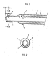
- the inner tube 1 has a closed tip, in which a laterally arranged suction opening 3 is formed.
- the distance c in FIG. 1 can be, for example, 0.5 mm and the diameter b 0.3 mm. In general, for a set of handles for performing a lens star surgery, the distance c is between 0.5 and 0.7 mm and the diameter b of the suction openings 3 with different sizes is between 0.3 and 0.7 mm.
- the outer tube 2 is provided adjacent to its front end with two rinsing openings 4, which are preferably arranged at 45 ° to the suction opening 3, and only one of which is visible in FIG. 1.
- the diameter of the two rinsing openings is 0.6 mm in the illustrated embodiment.
- the tip of the inner tube 1 can have a distance from the front end of the outer tube between 1.3 and 1.5 mm.
- both flushing openings 4 are approximately 45 ° offset from the suction opening 3
- an intensive flushing can be achieved in the anterior chamber of the eye, because both flushing currents can be directed onto the inner wall of the rear lens capsule, so that along the relatively short path between the Both flushing openings 4 and the intermediate suction opening 3, a vortex flow directed towards the suction opening can be achieved on both sides, which enables intensive flushing and thus better removal of the lens debris.
- a polishing surface 8 is provided on the side opposite the suction opening 3, which is preferably formed by a layer of sintered diamond powder. It is expedient on the side of the outer side opposite the two rinsing openings Tube 2 a stop 5 serving as an Irish hook is formed, with which the iris can be pulled apart if it becomes smaller again after an operation after a certain time.
- the handle shown in FIG. 1 is the handle in a set of handles normally used for performing an operation that has the suction opening 3 with the smallest diameter or the smallest cross-sectional area. Therefore, no additional polishing cannula has to be inserted into the eye, which reduces the risk of the risk of injury resulting from insertion and removal.
- the protruding end of the inner tube can be straight or bent. It is also possible to form the axis of the two coaxial tubes 1, 2 in an arc shape, so that a better penetration into the angle of the eye chamber can be achieved, since then the patient's nose is not disturbed.
- the polishing surface 8 does not have a disruptive effect in the normal procedure for vacuuming lens debris, but enables polishing and thus also the extraction of the abraded particles without further ado.
Abstract
Description
Die Neuerung betrifft einen Handgriff mit einer Doppelkanüle zum Absaugen von Linsentrümmern bei der Durchführung von Linsenstar-Operationen.The innovation relates to a handle with a double cannula for aspirating lens debris when performing lens star surgery.
Es sind bereits Linsen-Absauggeräte für medizinische Zwecke bekannt, für die ein oder mehrere derartige Handgriffe mit einer Doppelkanüle zum Absaugen von Linsentrümmern vorgesehen sind (DE-GM 84 37 836), wobei die Doppelkanüle aus zwei koaxialen Röhrchen besteht, wovon das innere Röhrchen eine geschlossene Spitze und eine seitlich angeordnete Saugöffnung aufweist. Das vordere Ende des äußeren Röhrchens ist in einem Abstand von der Spitze mit dem inneren Röhrchen verbunden und weist zwei seitlich angeordnete Spülöffnungen auf, die vorzugsweise in Umfangsrichtung der Doppelkanüle relativ zu der Saugöffnung zumindest angenähert um 45° versetzt angeordnet sind.Lens suction devices for medical purposes are already known, for which one or more such handles are provided with a double cannula for suctioning lens debris (DE-GM 84 37 836), the double cannula consisting of two coaxial tubes, of which the inner tube is one has a closed tip and a suction opening on the side. The front end of the outer tube is connected to the inner tube at a distance from the tip and has two laterally arranged rinsing openings, which are preferably offset at least approximately 45 ° relative to the suction opening in the circumferential direction of the double cannula.
Üblicherweise findet in Verbindung mit einem Absauggerät ein Satz von derartigen Handgriffen Verwendung, wobei die Saugöffnung am vorderen Ende der inneren Röhrchen der Handgriffe einen unterschiedlichen Durchmesser aufweist, so daß bei Durchführung einer Operation zunächst größere und dann kleinere Teilchen von Linsentrümmern abgesaugt werden können. Bei den meisten Operationen werden zwei oder drei Handgriffe dieser Art mit einer unterschiedlichen Saugöffnung benutzt. Ferner findet bei der Durchführung einer Operation mit einem derartigen Absauggerät noch eine Polierkanüle Verwendung, die mit Diamantpulver beschichtet ist, um durch Polieren der hinteren Kapsel zu verhindern, daß sekundäre Katarakte verursacht werden können.Usually, a set of such handles is used in connection with a suction device, the suction opening at the front end of the inner tubes of the handles having a different diameter, so that when an operation is carried out, first larger and then smaller particles can be sucked out of lens debris. Most operations use two or three handles of this type with a different suction opening. Furthermore, when performing an operation with such a suction device, a polishing cannula is used which is coated with diamond powder in order to prevent secondary cataracts by polishing the rear capsule can be caused.
Es ist Aufgabe der Neuerung, einen Handgriff dieser Art derart zu gestalten, daß einerseits bei der Durchführung einer Operation eine Zeitersparnis erzielbar ist, und daß andererseits die Operation weniger traumatisch durchgeführt werden kann.It is the task of the innovation to design a handle of this type in such a way that, on the one hand, time can be saved when performing an operation, and on the other hand that the operation can be carried out less traumatically.
Diese Aufgabe wird bei einem Handgriff der eingangs genannten Art erfindungsgemäß dadurch gelöst, daß auf der der Saugöffnung gegenüberliegenden Seite eine Polierfläche vorgesehen ist. Bei einer derartigen Ausgestaltung können beim Polieren abgeriebene Teilchen einerseits sofort abgesaugt werden. Eine derartige Polierfläche stört nicht beim normalen Arbeiten. Andererseits wird für den Chirurgen eine Zeitersparnis erzielt und vor allem für den Patienten die Verletzungsgefahr verringert, weil bei Benutzung eines Handgriffs gemäß der Erfindung zumindest einmal weniger eine Spitze eingeschoben und herausgezogen werden muß. Da eine zusätzliche Polierkanüle nicht mehr erforderlich ist, ergeben sich auch weitere Vorteile hinsichtlich Aufbewahrung und Herstellung eines Satzes von für eine Operation erforderlichen Instrumenten. Ferner ist die Ausbildung eines Irishäkchens an dem Handgriff mit der Polierfläche besonders zweckmäßig, weil die durch die Iris begrenzte Öffnung nur anfänglich mit Medikamenten vergrößert werden kann, so daß diese Öffnung nahe dem Ende der Operation wesentlich kleiner ist.This object is achieved according to the invention in a handle of the type mentioned at the outset in that a polishing surface is provided on the side opposite the suction opening. With such a configuration, particles that have been rubbed off during polishing can be sucked off immediately. Such a polishing surface does not interfere with normal work. On the other hand, time is saved for the surgeon and, above all, the risk of injury is reduced for the patient, because when using a handle according to the invention, a tip has to be inserted and pulled out at least once less. Since an additional polishing cannula is no longer required, there are also further advantages with regard to the storage and manufacture of a set of instruments required for an operation. Furthermore, the formation of an Irish hook on the handle with the polishing surface is particularly expedient because the opening delimited by the iris can only be enlarged initially with medication, so that this opening is substantially smaller near the end of the operation.
Anhand der Zeichnung soll die Neuerung beispielsweise näher erläutert werden. Es zeigen:
- Fig. 1 und 2 Schnittansichten eines Ausführungsbeispiels gemäß der Neuerung.
- 1 and 2 sectional views of an embodiment according to the innovation.
Bei dem in Fig. 1 dargestellten Ausführungsbeispiel ist eine geradlinige Anordnung der beiden koaxial zueinander angeordneten Röhrchen 1 und 2 vorgesehen. Das innere Röhrchen 1 weist eine geschlossene Spitze auf, in der eine seitlich angeordnete Saugöffnung 3 ausgebildet ist. Der Abstand c in Fig. 1 kann beispielsweise 0,5 mm und der Durchmesser b 0,3 mm betragen. Im allgemeinen beträgt bei einem Satz von Handgriffen für die Durchführung einer Linsenstar-Operation der Abstand c zwischen 0,5 und 0,7 mm und der Durchmesser b der Saugöffnungen 3 mit unterschiedlicher Größe liegt zwischen 0,3 und 0,7 mm. Das äußere Röhrchen 2 ist angrenzend an sein vorderes Ende mit zwei Spülöffnungen 4 versehen, die vorzugsweise um 45° versetzt zu der Saugöffnung 3 angeordnet sind, und von denen nur eine in Fig. 1 sichtbar ist. Der Durchmesser der beiden Spülöffnungen beträgt bei dem dargestellten Ausführungsbeispiel 0,6 mm. Die Spitze des inneren Röhrchens 1 kann einen Abstand von dem vorderen Endes des äußeren Röhrchens zwischen 1,3 und 1,5 mm aufweisen.In the embodiment shown in Fig. 1, a straight line arrangement of the two coaxially arranged
Wenn die beiden Spülöffnungen 4 angenähert um 45° versetzt zu der Saugöffnung 3 sind, kann eine intensive Spülung in der Vorderkammer des Auges erzielt werden, weil beide Spülströme auf die Innenwand der hinteren Linsenkapsel gerichtet werden können, so daß entlang des verhältnismäßig kurzen Wegs zwischen den beiden Spülöffnungen 4 und der dazwischenliegenden Saugöffnung 3 beidseitig eine zu der Saugöffnung gerichtete Wirbelströmung erzielt werden kann, die eine intensive Spülung und damit eine bessere Entfernung der Linsentrümmer ermöglicht.If the two flushing openings 4 are approximately 45 ° offset from the
Gemäß der Neuerung ist auf der der Saugöffnung 3 gegenüberliegenden Seite eine Polierfläche 8 vorgesehen, die vorzugsweise durch eine Schicht aus aufgesintertem Diamantpulver gebildet ist. Zweckmäßigerweise ist auf der den beiden Spülöffnungen gegenüberliegenden Seite des äußeren Röhrchens 2 ein als Irishäkchen dienender Anschlag 5 ausgebildet, mit dem die Iris auseinandergezogen werden kann, wenn sie bei einer Operation nach einer gewissen Zeit wieder kleiner wird. Der in Fig. 1 dargestellte Handgriff ist derjenige Handgriff in einem Satz von normalerweise für die durchführung einer Operation benutzten Handgriffen, der die Saugöffnung 3 mit dem kleinsten Durchmesser oder der kleinsten Querschnittsfläche hat. Deshalb muß keine zusätzliche Polierkanüle in das Auge eingeführt werden, wodurch das Risiko der durch das Einschieben und Herausziehen gegebenen Verletzungsgefahr verringert wird.According to the innovation, a
Das vorragende Ende des inneren Röhrchens kann geradlinig oder abgebogen ausgebildet sein. Es ist ferner möglich, die Achse der beiden koaxialen Röhrchen 1,2 bogenförmig auszubilden, so daß ein besseres Eindringen in die Augenkammerwinkel erzielbar ist, da dann die Nase des Patienten dabei nicht stört.The protruding end of the inner tube can be straight or bent. It is also possible to form the axis of the two
Die Polierfläche 8 wirkt sich bei der normalen Arbeitsweise zum Absaugen von Linsentrümmern nicht störend aus, ermöglicht aber ohne weiteres ein Polieren und damit auch das Absaugen der dabei abgeriebenen Teilchen.The
Claims (6)
Applications Claiming Priority (2)
| Application Number | Priority Date | Filing Date | Title |
|---|---|---|---|
| DE8704459U | 1987-03-25 | ||
| DE8704459U DE8704459U1 (en) | 1987-03-25 | 1987-03-25 |
Publications (2)
| Publication Number | Publication Date |
|---|---|
| EP0283929A1 true EP0283929A1 (en) | 1988-09-28 |
| EP0283929B1 EP0283929B1 (en) | 1991-09-04 |
Family
ID=6806287
Family Applications (1)
| Application Number | Title | Priority Date | Filing Date |
|---|---|---|---|
| EP88104237A Expired - Lifetime EP0283929B1 (en) | 1987-03-25 | 1988-03-17 | Hand tip with double lumen |
Country Status (2)
| Country | Link |
|---|---|
| EP (1) | EP0283929B1 (en) |
| DE (2) | DE8704459U1 (en) |
Cited By (7)
| Publication number | Priority date | Publication date | Assignee | Title |
|---|---|---|---|---|
| FR2741522A1 (en) * | 1995-11-27 | 1997-05-30 | Cornier Edgard | Endo=uterine tissue sampler, designed for one=time use |
| WO1997019642A1 (en) * | 1995-11-27 | 1997-06-05 | Laboratoire C.C.D. | Device for collecting endometrial fragments |
| FR2750030A1 (en) * | 1996-06-25 | 1997-12-26 | Ccd Lab | Collector for uterine wall fragments |
| EP0864310A1 (en) * | 1997-03-14 | 1998-09-16 | Inami & Co., Ltd. | Membrane eraser |
| EP0928177A1 (en) * | 1996-08-22 | 1999-07-14 | Oversby Pty. Ltd. | Intraocular irrigation/aspiration device |
| EP1216001A1 (en) * | 1999-09-13 | 2002-06-26 | Synergetics, Inc. | Adjustable stiffness membrane scraper |
| FR2855401A1 (en) * | 2003-05-28 | 2004-12-03 | Frederic Hehn | OPHTHALMIC SURGERY INSTRUMENT |
Citations (3)
| Publication number | Priority date | Publication date | Assignee | Title |
|---|---|---|---|---|
| US3809093A (en) * | 1972-04-14 | 1974-05-07 | S Abraham | Surgical tool |
| US3867947A (en) * | 1973-01-26 | 1975-02-25 | Colin B Schack | Amniotomy glove |
| US3937222A (en) * | 1973-11-09 | 1976-02-10 | Surgical Design Corporation | Surgical instrument employing cutter means |
-
1987
- 1987-03-25 DE DE8704459U patent/DE8704459U1/de not_active Expired
-
1988
- 1988-03-17 DE DE8888104237T patent/DE3864548D1/en not_active Expired - Fee Related
- 1988-03-17 EP EP88104237A patent/EP0283929B1/en not_active Expired - Lifetime
Patent Citations (3)
| Publication number | Priority date | Publication date | Assignee | Title |
|---|---|---|---|---|
| US3809093A (en) * | 1972-04-14 | 1974-05-07 | S Abraham | Surgical tool |
| US3867947A (en) * | 1973-01-26 | 1975-02-25 | Colin B Schack | Amniotomy glove |
| US3937222A (en) * | 1973-11-09 | 1976-02-10 | Surgical Design Corporation | Surgical instrument employing cutter means |
Cited By (11)
| Publication number | Priority date | Publication date | Assignee | Title |
|---|---|---|---|---|
| FR2741522A1 (en) * | 1995-11-27 | 1997-05-30 | Cornier Edgard | Endo=uterine tissue sampler, designed for one=time use |
| WO1997019642A1 (en) * | 1995-11-27 | 1997-06-05 | Laboratoire C.C.D. | Device for collecting endometrial fragments |
| US6042552A (en) * | 1995-11-27 | 2000-03-28 | Laboratoire C.C.D. | Device for collecting endometrial fragments |
| FR2750030A1 (en) * | 1996-06-25 | 1997-12-26 | Ccd Lab | Collector for uterine wall fragments |
| EP0928177A1 (en) * | 1996-08-22 | 1999-07-14 | Oversby Pty. Ltd. | Intraocular irrigation/aspiration device |
| EP0928177A4 (en) * | 1996-08-22 | 2004-07-28 | Oversby Pty Ltd | Intraocular irrigation/aspiration device |
| EP1779825A3 (en) * | 1996-08-22 | 2010-08-25 | Oversby Pty. Ltd. | Intraocular irrigation/aspiration device |
| EP0864310A1 (en) * | 1997-03-14 | 1998-09-16 | Inami & Co., Ltd. | Membrane eraser |
| EP1216001A1 (en) * | 1999-09-13 | 2002-06-26 | Synergetics, Inc. | Adjustable stiffness membrane scraper |
| EP1216001A4 (en) * | 1999-09-13 | 2006-02-01 | Synergetics Inc | Adjustable stiffness membrane scraper |
| FR2855401A1 (en) * | 2003-05-28 | 2004-12-03 | Frederic Hehn | OPHTHALMIC SURGERY INSTRUMENT |
Also Published As
| Publication number | Publication date |
|---|---|
| DE3864548D1 (en) | 1991-10-10 |
| DE8704459U1 (en) | 1988-07-21 |
| EP0283929B1 (en) | 1991-09-04 |
Similar Documents
| Publication | Publication Date | Title |
|---|---|---|
| DE60304681T2 (en) | INFUSION DEVICE WITH NADELSCHUTZHÜLSE | |
| DE2915425C2 (en) | Suction control device for an endoscope | |
| DE69632603T2 (en) | Surgical scalpel with a protective cover and with a blade extractor | |
| DE19633124B4 (en) | Scraping or cutting instrument | |
| DE2950323C2 (en) | Suction instrument for medical purposes | |
| DE4019204A1 (en) | SURGICAL INSTRUMENT AND METHOD FOR REMOVING THE EYE LENS | |
| DE4305226A1 (en) | Additional device for needles for transcutaneous biopsy - involves structure insertable in proximal end of needle, pushed in between inner walling of needle and tissue cylinder to be investigated | |
| EP0314896A2 (en) | Thromboembolectomy device | |
| WO1997018745A2 (en) | Shaving or cutting instrument | |
| DE2540536A1 (en) | SUCTION CATHETER | |
| EP0393343B1 (en) | Uretero-renoscope | |
| DE3326648C2 (en) | Balloon catheter | |
| EP0283929B1 (en) | Hand tip with double lumen | |
| DE10032766B4 (en) | Endoscopic high frequency meter | |
| DE3936811A1 (en) | Endoscope for removal of gall stones - has dilator formed from several telescopic tubes | |
| EP0218809A1 (en) | Guiding probe | |
| DE3918719C2 (en) | ||
| WO2007003281A1 (en) | Device for use in eye surgery | |
| DE102018209194B4 (en) | Device for providing and inserting a graft or implant into a human or animal body and ready-to-use set comprising this device | |
| DE4139196C2 (en) | Swivel arm for holding a saliva suction device | |
| DE4422426C2 (en) | Surgical instrument for removing tissue or cartilage | |
| DE2638832A1 (en) | DEVICE FOR SUCTIONING CONTRAST AGENT FROM THE SPINAL CANAL OF A PATIENT | |
| DE19823755A1 (en) | Device for widening and restoring the tear duct on the human eye, through which tear fluid reaches the nasal cavity from the eye | |
| EP0280783A1 (en) | Handgrip with double cannula | |
| DE8437836U1 (en) | Handle with a double cannula |
Legal Events
| Date | Code | Title | Description |
|---|---|---|---|
| PUAI | Public reference made under article 153(3) epc to a published international application that has entered the european phase |
Free format text: ORIGINAL CODE: 0009012 |
|
| AK | Designated contracting states |
Kind code of ref document: A1 Designated state(s): CH DE FR GB IT LI NL |
|
| 17P | Request for examination filed |
Effective date: 19890217 |
|
| 17Q | First examination report despatched |
Effective date: 19910128 |
|
| GRAA | (expected) grant |
Free format text: ORIGINAL CODE: 0009210 |
|
| AK | Designated contracting states |
Kind code of ref document: B1 Designated state(s): CH DE FR GB IT LI NL |
|
| PG25 | Lapsed in a contracting state [announced via postgrant information from national office to epo] |
Ref country code: NL Effective date: 19910904 Ref country code: GB Effective date: 19910904 Ref country code: IT Free format text: LAPSE BECAUSE OF FAILURE TO SUBMIT A TRANSLATION OF THE DESCRIPTION OR TO PAY THE FEE WITHIN THE PRE;WARNING: LAPSES OF ITALIAN PATENTS WITH EFFECTIVE DATE BEFORE 2007 MAY HAVE OCCURRED AT ANY TIME BEFORE 2007. THE CORRECT EFFECTIVE DATE MAY BE DIFFERENT FROM THE ONE RECORDED.SCRIBED TIME-LIMIT Effective date: 19910904 |
|
| REF | Corresponds to: |
Ref document number: 3864548 Country of ref document: DE Date of ref document: 19911010 |
|
| EN | Fr: translation not filed | ||
| PG25 | Lapsed in a contracting state [announced via postgrant information from national office to epo] |
Ref country code: FR Effective date: 19920124 |
|
| NLV1 | Nl: lapsed or annulled due to failure to fulfill the requirements of art. 29p and 29m of the patents act | ||
| GBV | Gb: ep patent (uk) treated as always having been void in accordance with gb section 77(7)/1977 [no translation filed] | ||
| PLBE | No opposition filed within time limit |
Free format text: ORIGINAL CODE: 0009261 |
|
| STAA | Information on the status of an ep patent application or granted ep patent |
Free format text: STATUS: NO OPPOSITION FILED WITHIN TIME LIMIT |
|
| 26N | No opposition filed | ||
| REG | Reference to a national code |
Ref country code: FR Ref legal event code: ST |
|
| PGFP | Annual fee paid to national office [announced via postgrant information from national office to epo] |
Ref country code: DE Payment date: 19950413 Year of fee payment: 8 |
|
| PGFP | Annual fee paid to national office [announced via postgrant information from national office to epo] |
Ref country code: CH Payment date: 19950418 Year of fee payment: 8 |
|
| PG25 | Lapsed in a contracting state [announced via postgrant information from national office to epo] |
Ref country code: LI Effective date: 19960331 Ref country code: CH Effective date: 19960331 |
|
| REG | Reference to a national code |
Ref country code: CH Ref legal event code: PL |
|
| PG25 | Lapsed in a contracting state [announced via postgrant information from national office to epo] |
Ref country code: DE Effective date: 19961203 |