EP0277369A2 - Dilatation catheter with angled balloon - Google Patents
Dilatation catheter with angled balloon Download PDFInfo
- Publication number
- EP0277369A2 EP0277369A2 EP87119368A EP87119368A EP0277369A2 EP 0277369 A2 EP0277369 A2 EP 0277369A2 EP 87119368 A EP87119368 A EP 87119368A EP 87119368 A EP87119368 A EP 87119368A EP 0277369 A2 EP0277369 A2 EP 0277369A2
- Authority
- EP
- European Patent Office
- Prior art keywords
- balloon
- dilatation catheter
- angled
- tubular member
- extending
- Prior art date
- Legal status (The legal status is an assumption and is not a legal conclusion. Google has not performed a legal analysis and makes no representation as to the accuracy of the status listed.)
- Granted
Links
Images

Classifications
-
- A—HUMAN NECESSITIES
- A61—MEDICAL OR VETERINARY SCIENCE; HYGIENE
- A61M—DEVICES FOR INTRODUCING MEDIA INTO, OR ONTO, THE BODY; DEVICES FOR TRANSDUCING BODY MEDIA OR FOR TAKING MEDIA FROM THE BODY; DEVICES FOR PRODUCING OR ENDING SLEEP OR STUPOR
- A61M25/00—Catheters; Hollow probes
- A61M25/10—Balloon catheters
- A61M25/104—Balloon catheters used for angioplasty
-
- A—HUMAN NECESSITIES
- A61—MEDICAL OR VETERINARY SCIENCE; HYGIENE
- A61M—DEVICES FOR INTRODUCING MEDIA INTO, OR ONTO, THE BODY; DEVICES FOR TRANSDUCING BODY MEDIA OR FOR TAKING MEDIA FROM THE BODY; DEVICES FOR PRODUCING OR ENDING SLEEP OR STUPOR
- A61M25/00—Catheters; Hollow probes
- A61M25/10—Balloon catheters
- A61M25/1002—Balloon catheters characterised by balloon shape
-
- A—HUMAN NECESSITIES
- A61—MEDICAL OR VETERINARY SCIENCE; HYGIENE
- A61M—DEVICES FOR INTRODUCING MEDIA INTO, OR ONTO, THE BODY; DEVICES FOR TRANSDUCING BODY MEDIA OR FOR TAKING MEDIA FROM THE BODY; DEVICES FOR PRODUCING OR ENDING SLEEP OR STUPOR
- A61M25/00—Catheters; Hollow probes
- A61M25/10—Balloon catheters
- A61M2025/1043—Balloon catheters with special features or adapted for special applications
- A61M2025/1079—Balloon catheters with special features or adapted for special applications having radio-opaque markers in the region of the balloon
-
- A—HUMAN NECESSITIES
- A61—MEDICAL OR VETERINARY SCIENCE; HYGIENE
- A61M—DEVICES FOR INTRODUCING MEDIA INTO, OR ONTO, THE BODY; DEVICES FOR TRANSDUCING BODY MEDIA OR FOR TAKING MEDIA FROM THE BODY; DEVICES FOR PRODUCING OR ENDING SLEEP OR STUPOR
- A61M25/00—Catheters; Hollow probes
- A61M25/0021—Catheters; Hollow probes characterised by the form of the tubing
- A61M25/0041—Catheters; Hollow probes characterised by the form of the tubing pre-formed, e.g. specially adapted to fit with the anatomy of body channels
-
- A—HUMAN NECESSITIES
- A61—MEDICAL OR VETERINARY SCIENCE; HYGIENE
- A61M—DEVICES FOR INTRODUCING MEDIA INTO, OR ONTO, THE BODY; DEVICES FOR TRANSDUCING BODY MEDIA OR FOR TAKING MEDIA FROM THE BODY; DEVICES FOR PRODUCING OR ENDING SLEEP OR STUPOR
- A61M25/00—Catheters; Hollow probes
- A61M25/01—Introducing, guiding, advancing, emplacing or holding catheters
- A61M25/0105—Steering means as part of the catheter or advancing means; Markers for positioning
- A61M25/0108—Steering means as part of the catheter or advancing means; Markers for positioning using radio-opaque or ultrasound markers
Definitions
- This invention relates to a dilatation catheter with angled balloon and method.
- Another object of the invention is to provide a dilatation catheter of the above character which can be used for treating stenoses which occur at an angle.
- Another object of the invention is to provide a dilatation catheter of the above character in which the angled balloons can be substantially straightened to facilitate their insertion into the vessel of the patient.
- Another object of the invention is to provide a dilatation catheter and above of the above character in which various angles can be achieved.
- Another object of the invention is to provide a dilatation catheter in which markers are provided.
- Another object of the invention is to provide a dilatation catheter of the above character in which directional markers are provided to indicate the orientation of the balloon in the vessel in the patient.
- the dilatation catheter with angled balloon consists of a flexible elongate tubular member having first and second lumens extending therethrough and having proximal and distal extremities.
- An angled balloon is carried by the distal extremity of the tubular member.
- the elongate tubular member includes a tubular element which extends through the balloon and has the first lumen extending therethrough.
- the first lumen is of a size that is capable of receiving a guide wire so that a guide wire can extend through the balloon.
- Means is provided for establishing communication between the second lumen and the interior of the balloon for inflating and deflating the balloon.
- the balloon has a configuration so that when it is inflated it will subtend a suitable angle ranging from about 35° or less to about 160° or more.
- the dilatation catheter 11 of the present invention consists of a flexible elongate tubular member 12 which carries first and second lumens or flow passages 13 and 14 which extend therethrough.
- the lumens or flow passages 13 and 14 can be provided in a suitable manner, as for example, extruding the tubular member 12 so it is provided with two of such passages extending longitudinally of the same.
- the two flow passages 13 and 14 can be provided with a first lumen or flow passage 13 which extends through an inner tubular member 16 and in which the second lumen or flow passage 14 is formed by an annular flow passage or lumen 14 extending between the outer surface of the inner tubular member 16 and the inner surface of an outer tubular member 17.
- the tubular member 12, if formed with this co-axial construction can be formed in the manner described in U.S. Letters Patent 4,323,071.
- the inner tubular member 16 can be formed of suitable plastic such as polyester or polyolefin.
- the outer tubular member 17 also can be formed of a polyolefin or a polyester.
- the outer tubular member 17 can have suitable dimensions such as an inside diameter of 1.15 mm (.046 inch) with an outside diameter varying from 1.4 - 1.43 mm (.056 to .057 inch).
- the inner tubular member 16 can have a suitable inner diameter such as 0.5 mm (.020 inch) and an outer diameter of 0.9 mm (.035 inch).
- the outer tubular member can, for example, have an outer diameter as large as .064 inch or as small as 0.5 mm (.020 inch).
- An angled balloon 21 is carried by the distal extremity of the tubular member 12.
- the angled balloon 21 can be formed with a bend 22 so that the interior angle subtends an angle A ranging from about 35° or less to about 160° or more.
- Such an angled balloon can be made in several different ways.
- the balloon can be first formed in a mold, as for example, a glass mold which has the desired configuration for the balloon.
- the balloon can be formed in the conventional 180°, or straight, configuration and then heat treating the same, as for example, by the use of heated air or a heated solid coming into contact with the balloon material at an appropriate area to form the desired angle by introducing shrinkage in that area of the balloon.
- the angled balloon 21 is formed of a suitable polymeric material such as a polyester which can be formed with very thin walls of great strength. This material can be extruded and blown to form an angled balloon.
- a suitable polymeric material such as a polyester which can be formed with very thin walls of great strength. This material can be extruded and blown to form an angled balloon.
- a balloon can have an outside diameter, as for example, ranging from about 1.5 to about 4.0 millimeters.
- Such a balloon can have a wall thickness as thin as 0.025 mm (.001 inch) and still be inflated to pressures in the range of 10 to 15 atmospheres.
- the inner tubular member 16 also can be provided with a bend 26 of the same angle as the bend 22 provided for the angled balloon.
- the angled balloon 21, after it has been formed, can be secured to the distal extremity of the tubular member 12.
- the proximal portion 28 of the balloon can be necked down and secured to the distal extremity of the outer tubular member 12 by suitable means such as an adhesive or by heat if irradiated plastic is used for the balloon.
- the distal extremity 29 of the balloon is also necked down and can be secured to the distal extremity of the inner tubular member 16 by a shrink fit or, alternatively, by the use of an adhesive.
- means is provided in the form of the first lumen or flow passage 13 having an inside diameter of 0.5 mm (.020 inch) extending through the tubular member 16 which is adapted to receive a guide wire 31 of a conventional type, as for example, the .018 "Hi-Torque Floppy" (trademark) guide wire manufactured and sold by Advanced Cardiovascular Systems, Inc., of Mountain View, California.
- a guide wire 31 of a conventional type, as for example, the .018 "Hi-Torque Floppy" (trademark) guide wire manufactured and sold by Advanced Cardiovascular Systems, Inc., of Mountain View, California.
- means is provided for establishing communication between the second lumen or flow passage 14 and the interior of the angled balloon 21 so that the balloon can be inflated and deflated as hereinafter described.
- the distal extremity of the inner tubular member 16 can be rounded as shown and can be relatively soft.
- the distal extremity can have a maximum diameter of, for example, 1.13 mm (0.045 inch) and a length of approximately 9 millimeters.
- the balloon itself can have a length of 10-50 millimeters and preferably approximately 30 millimeters with 15 millimeters being provided on each side of the bend 22.
- a three-arm adapter 36 is mounted on the proximal extremity of the tubular member 12.
- the side arm 37 of the adapter 36 is adapted to receive a vent tube 38 for venting air from the balloon 21 as it is inflated.
- the center arm 39 is in communication with the first lumen or flow passage 13 which extends completely through the dilatation catheter 11 and particularly through the balloon 21.
- Another side arm 41 is provided which is in communication with the second lumen or flow passage 14 and serves as a port for introducing a liquid medium for inflating and deflating the angled balloon 21.
- Suitable means is provided for ascertaining the position of the balloon in the distal extremity of the catheter 11 when it is being used in an angioplasty procedure and consists of radiopaque markers.
- a pair of radiopaque markers 46 and 47 can be provided within the balloon on the tubular member 16 adjacent to the proximal and distal extremities of the balloon.
- An additional marker 48 can be provided adjacent the tip of the inner tubular member 16.
- the radiopaque markers 46, 47 and 48 can be in a suitable form, as for example, gold bands.
- the angled balloon 21 it is desirable to form the angled balloon with an angle A which is less than the desired angle, as for example, 45° as shown in Figure 3. This is because when the guide wire 31 is inserted through the balloon as is shown in Figure 4, the guide wire will decrease the angle of the bend, as for example, by changing the angle of the balloon from approximately 45° to approximately 85°.
- One way to accomplish this is to make a vent tube 38 stiff enough to provide the desired degree of straightening when it is inserted to the distal extremity of the balloon.
- the relatively stiff vent tube has a tendency to remain essentially straight and this tube and the guide wire acting together can straighten the balloon so it only subtends a small angle B (see Figure 5), e.g., 0° to 15°, with the axis of the catheter shift.
- a stiffer guide wire can be utilized until the balloon has advanced to a location near the stenosis. The still guide wire can be removed and a more flexible guide wire exchanged therefor and inserted into the balloon.
- an angled sleeve 49 is provided which is slipped over the balloon 21 and is frictionally retained thereon.
- the sleeve has a length slightly greater than the length of the balloon 21.
- the sleeve can be formed of plastic having a wall thickness so that the sleeve is relatively rigid.
- vent tube is then withdrawn so that its distal end is near the proximal end of the balloon unless it is being utilized to straighten the balloon, in which case it is positioned as desired to provide the desired degree of straightening.
- a guide wire 31 is selected and introduced through the first lumen 13 and through the angled balloon 21 as shown in Figure 4 so that the balloon with the guide wire therein assumes a conformation with the desired angle. If this angle is approximately 85 to 90°, assuming that is the angle desired by the physician performing the angioplasty procedure, frictional means may thereafter be inserted to further straighten the balloon so that it can be inserted into the vessel. As explained previously, this can be accomplished by utilizing the vent tube or a stiffer guide wire to straighten the angled balloon.
- the balloon After the balloon has been straightened to the angle B of 0 to 15° from the catheter shaft, it can be advanced into the vessel of the patient into the region of the stenosis by first advancing the guide wire 31 in the vessel and then advancing the dilatation catheter 11 on the guide wire until it reaches the stenosis.
- the vent tube 38 can be withdrawn permitting the balloon to gradually assume its angled condition and to permit it to be advanced into and through the stenosis.
- the balloon After it is ascertained by observing the markers on the catheter that the balloon had been advanced sufficiently far, the balloon can be inflated by the introduction of a radiographic contrast liquid into the inflation port 41.
- the angled balloon can be deflated and the dilatation catheter 11 and the guide wire 31 removed from the vessel in a conventional manner.
- suitable spaced apart markers 51 and 52 can be placed within the balloon 21 (see Figure 6) to make it possible for the physician viewing the balloon 21 under a fluoroscope to ascertain its angular position before inflation of the same.
- the markers 51 and 52 can be provided on the inner tubular member 16 within the balloon adjacent the proximal and distal extremities of the balloon 21.
- the markers 51 and 52 have a distinctive relationship to the angular position of the balloon.
- the markers 51 and 52 are formed of a suitable material such as gold ribbon 53 with a suitable width such as 0.25 mm (.010 inch) and a thickness of 0.05 mm (.002 inch), which is wrapped onto a mandrel (not shown) to form a double helix as shown in Figure 7 by the solid and broken lines. A solder joint can be formed at the overlap of the gold ribbon.
- the ribbon 53 is trimmed and the markers 51 and 52 are then removed from the mandrel.
- the first double helix band or marker 51 is placed in an angular position on the inner member 16.
- the second double helix band or marker 52 is placed on the inner tubular member rotated by 90° from the position of the first band 51.
- Each of these double bands 51 and 52 can be fastened to the inner tubular member 16 by suitable means such as an adhesive.
- suitable means such as an adhesive.
Abstract
Description
- This invention relates to a dilatation catheter with angled balloon and method.
- In angioplasty procedures, it has been found that there are certain vessels in the heart and in other parts of the body such as the kidneys which are difficult to treat with conventional straight balloon dilatation catheters. This is particularly true where the stenosis occurs in a bend in the vessel which makes it very difficult to treat the stenosis. There is therefore a need for a new and improved dilatation catheter and method which can be utilized for treating stenoses of that type.
- In general, it is an object of the present invention to provide a dilatation catheter having an angled balloon.
- Another object of the invention is to provide a dilatation catheter of the above character which can be used for treating stenoses which occur at an angle.
- Another object of the invention is to provide a dilatation catheter of the above character in which the angled balloons can be substantially straightened to facilitate their insertion into the vessel of the patient.
- Another object of the invention is to provide a dilatation catheter and above of the above character in which various angles can be achieved.
- Another object of the invention is to provide a dilatation catheter in which markers are provided.
- Another object of the invention is to provide a dilatation catheter of the above character in which directional markers are provided to indicate the orientation of the balloon in the vessel in the patient.
- Additional objects and features of the invention will appear from the following description in which the preferred embodiments are set forth in detail in conjunction with the accompanying drawings.
-
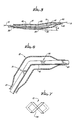
- Figure 1 is a side elevational view partially in cross section of a dilatation catheter having angled balloon incorporating the present invention and having an angled protective sleeve on the angled balloon.
- Figure 2 is a cross-sectional view taken along the line 2-2 of Figure 1.
- Figure 3 is an enlarged cross-sectional view of the distal extremity of the catheter shown in Figure 1 but without a guide wire extending through the same.
- Figure 4 is a view similar to that shown in Figure 3 but with a guide wire extending through the balloon.
- Figure 5 is a view similar to that shown in Figure 3 but showing the angled balloon straightened out in a manner so that it can be inserted into the vessel of the patient.
- Figure 6 is an enlarged side elevational view of the distal extremity of another embodiment of a dilatation catheter with angled balloon carrying directional markers.
- Figure 7 is a further enlargement of one of the directional markers shown in Figure 6.
- In general, the dilatation catheter with angled balloon consists of a flexible elongate tubular member having first and second lumens extending therethrough and having proximal and distal extremities. An angled balloon is carried by the distal extremity of the tubular member. The elongate tubular member includes a tubular element which extends through the balloon and has the first lumen extending therethrough. The first lumen is of a size that is capable of receiving a guide wire so that a guide wire can extend through the balloon. Means is provided for establishing communication between the second lumen and the interior of the balloon for inflating and deflating the balloon. The balloon has a configuration so that when it is inflated it will subtend a suitable angle ranging from about 35° or less to about 160° or more.
- More particularly, the dilatation catheter 11 of the present invention consists of a flexible elongate
tubular member 12 which carries first and second lumens orflow passages 13 and 14 which extend therethrough. The lumens orflow passages 13 and 14 can be provided in a suitable manner, as for example, extruding thetubular member 12 so it is provided with two of such passages extending longitudinally of the same. Alternatively, as shown in Figure 2, the twoflow passages 13 and 14 can be provided with a first lumen or flow passage 13 which extends through an innertubular member 16 and in which the second lumen orflow passage 14 is formed by an annular flow passage orlumen 14 extending between the outer surface of the innertubular member 16 and the inner surface of an outertubular member 17. Thetubular member 12, if formed with this co-axial construction can be formed in the manner described in U.S. Letters Patent 4,323,071. By way of example, the innertubular member 16 can be formed of suitable plastic such as polyester or polyolefin. The outertubular member 17 also can be formed of a polyolefin or a polyester. - By way of example, the outer
tubular member 17 can have suitable dimensions such as an inside diameter of 1.15 mm (.046 inch) with an outside diameter varying from 1.4 - 1.43 mm (.056 to .057 inch). In this example the innertubular member 16 can have a suitable inner diameter such as 0.5 mm (.020 inch) and an outer diameter of 0.9 mm (.035 inch). However, it should be understood that larger or smaller tubular members can be employed, if desired. The outer tubular member can, for example, have an outer diameter as large as .064 inch or as small as 0.5 mm (.020 inch). - An
angled balloon 21 is carried by the distal extremity of thetubular member 12. Theangled balloon 21 can be formed with abend 22 so that the interior angle subtends an angle A ranging from about 35° or less to about 160° or more. Such an angled balloon can be made in several different ways. By way of example, the balloon can be first formed in a mold, as for example, a glass mold which has the desired configuration for the balloon. alternatively, if it is not desired to utilize a mold, the balloon can be formed in the conventional 180°, or straight, configuration and then heat treating the same, as for example, by the use of heated air or a heated solid coming into contact with the balloon material at an appropriate area to form the desired angle by introducing shrinkage in that area of the balloon. Since it is often desirable a form a balloon which has an angle of approximately 90° with the guide wire inserted into the same, it is desirable to form the balloon with a lesser angle, as for example, 45° as shown in Figure 3 to accommodate forces applied on the balloon by the guide wire when the guide wire is inserted into the first lumen and extends through the first lumen and particularly through the portion of the first lumen which extends through the angled balloon. - The
angled balloon 21 is formed of a suitable polymeric material such as a polyester which can be formed with very thin walls of great strength. This material can be extruded and blown to form an angled balloon. By way of example, such a balloon can have an outside diameter, as for example, ranging from about 1.5 to about 4.0 millimeters. Such a balloon can have a wall thickness as thin as 0.025 mm (.001 inch) and still be inflated to pressures in the range of 10 to 15 atmospheres. If desired, the innertubular member 16 also can be provided with abend 26 of the same angle as thebend 22 provided for the angled balloon. - The
angled balloon 21, after it has been formed, can be secured to the distal extremity of thetubular member 12. If a separate balloon is used rather than an integral balloon, theproximal portion 28 of the balloon can be necked down and secured to the distal extremity of the outertubular member 12 by suitable means such as an adhesive or by heat if irradiated plastic is used for the balloon. Thedistal extremity 29 of the balloon is also necked down and can be secured to the distal extremity of the innertubular member 16 by a shrink fit or, alternatively, by the use of an adhesive. - As can be seen from the construction shown, means is provided in the form of the first lumen or flow passage 13 having an inside diameter of 0.5 mm (.020 inch) extending through the
tubular member 16 which is adapted to receive aguide wire 31 of a conventional type, as for example, the .018 "Hi-Torque Floppy" (trademark) guide wire manufactured and sold by Advanced Cardiovascular Systems, Inc., of Mountain View, California. As can be seen from the construction shown in Figure 4, means is provided for establishing communication between the second lumen orflow passage 14 and the interior of theangled balloon 21 so that the balloon can be inflated and deflated as hereinafter described. The distal extremity of the innertubular member 16 can be rounded as shown and can be relatively soft. The distal extremity can have a maximum diameter of, for example, 1.13 mm (0.045 inch) and a length of approximately 9 millimeters. The balloon itself can have a length of 10-50 millimeters and preferably approximately 30 millimeters with 15 millimeters being provided on each side of thebend 22. - A three-
arm adapter 36 is mounted on the proximal extremity of thetubular member 12. The side arm 37 of theadapter 36 is adapted to receive avent tube 38 for venting air from theballoon 21 as it is inflated. Thecenter arm 39 is in communication with the first lumen or flow passage 13 which extends completely through the dilatation catheter 11 and particularly through theballoon 21. Another side arm 41 is provided which is in communication with the second lumen orflow passage 14 and serves as a port for introducing a liquid medium for inflating and deflating theangled balloon 21. - Suitable means is provided for ascertaining the position of the balloon in the distal extremity of the catheter 11 when it is being used in an angioplasty procedure and consists of radiopaque markers. For example, as shown in Figure 1, a pair of
radiopaque markers tubular member 16 adjacent to the proximal and distal extremities of the balloon. Anadditional marker 48 can be provided adjacent the tip of the innertubular member 16. Theradiopaque markers - In making the
angled balloon 21, it is desirable to form the angled balloon with an angle A which is less than the desired angle, as for example, 45° as shown in Figure 3. This is because when theguide wire 31 is inserted through the balloon as is shown in Figure 4, the guide wire will decrease the angle of the bend, as for example, by changing the angle of the balloon from approximately 45° to approximately 85°. In order to make it easier to insert the angled balloon into the vessel, it is sometimes necessary to straighten the balloon in some suitable manner. One way to accomplish this is to make avent tube 38 stiff enough to provide the desired degree of straightening when it is inserted to the distal extremity of the balloon. The relatively stiff vent tube has a tendency to remain essentially straight and this tube and the guide wire acting together can straighten the balloon so it only subtends a small angle B (see Figure 5), e.g., 0° to 15°, with the axis of the catheter shift. If desired, in order to obtain sufficient straightening of the balloon, a stiffer guide wire can be utilized until the balloon has advanced to a location near the stenosis. The still guide wire can be removed and a more flexible guide wire exchanged therefor and inserted into the balloon. - In order to retain the desired bend in the
balloon 21 during shipment and storage before use of the catheter 11, anangled sleeve 49 is provided which is slipped over theballoon 21 and is frictionally retained thereon. The sleeve has a length slightly greater than the length of theballoon 21. The sleeve can be formed of plastic having a wall thickness so that the sleeve is relatively rigid. Thus, thesleeve 49 will retain the balloon at the desired angle during shipment and sterilization and storage. This ensures that theballoon 21 will have the desired angle when the catheter 11 is used. - Operation and use of the dilatation catheter 11 with angled balloon in performing the present method may now be briefly described as follows. let it be briefly assumed that it is desired to open a difficult stenosis which extends around an angle in an arterial vessel of a patient. A catheter with an angled balloon is selected. A
vent tube 38 is positioned in the balloon so that its distal extremity is near the distal extremity of the balloon. Theballoon 21 is filled in a conventional manner by introducing radiographic contrast liquid through the inflation port 41. As the liquid enters the interior of theangled balloon 21, the air in the balloon will be pushed forward and will be vented to atmosphere through thevent tube 38. Theballoon 21 is then deflated by withdrawing the radiographic contrast liquid therefrom and maintaining a vacuum within the balloon. The vent tube is then withdrawn so that its distal end is near the proximal end of the balloon unless it is being utilized to straighten the balloon, in which case it is positioned as desired to provide the desired degree of straightening. Thereafter aguide wire 31 is selected and introduced through the first lumen 13 and through theangled balloon 21 as shown in Figure 4 so that the balloon with the guide wire therein assumes a conformation with the desired angle. If this angle is approximately 85 to 90°, assuming that is the angle desired by the physician performing the angioplasty procedure, frictional means may thereafter be inserted to further straighten the balloon so that it can be inserted into the vessel. As explained previously, this can be accomplished by utilizing the vent tube or a stiffer guide wire to straighten the angled balloon. After the balloon has been straightened to the angle B of 0 to 15° from the catheter shaft, it can be advanced into the vessel of the patient into the region of the stenosis by first advancing theguide wire 31 in the vessel and then advancing the dilatation catheter 11 on the guide wire until it reaches the stenosis. After the stenosis has been reached and it is desired to have the balloon assume an angled conformation, as for example, approximately 90°, thevent tube 38 can be withdrawn permitting the balloon to gradually assume its angled condition and to permit it to be advanced into and through the stenosis. After it is ascertained by observing the markers on the catheter that the balloon had been advanced sufficiently far, the balloon can be inflated by the introduction of a radiographic contrast liquid into the inflation port 41. After the stenosis has been enlarged, the angled balloon can be deflated and the dilatation catheter 11 and theguide wire 31 removed from the vessel in a conventional manner. - It has been found that in many cases, regardless of the orientation of the
balloon 21 and its angle, when the balloon is inflated it will assume the conformation of the vessel in which it is disposed so that it will assume an angular position which corresponds to the angular position of the stenosis. This makes it unnecessary to rotate the distal extremity of the catheter so that the angular balloon has the desired angularity with the respect to the stenosis. - If it is desired to more closely track the angular position of the
angled balloon 21, suitable spaced apartmarkers 51 and 52 can be placed within the balloon 21 (see Figure 6) to make it possible for the physician viewing theballoon 21 under a fluoroscope to ascertain its angular position before inflation of the same. Themarkers 51 and 52 can be provided on theinner tubular member 16 within the balloon adjacent the proximal and distal extremities of theballoon 21. Themarkers 51 and 52 have a distinctive relationship to the angular position of the balloon. Themarkers 51 and 52 are formed of a suitable material such asgold ribbon 53 with a suitable width such as 0.25 mm (.010 inch) and a thickness of 0.05 mm (.002 inch), which is wrapped onto a mandrel (not shown) to form a double helix as shown in Figure 7 by the solid and broken lines. A solder joint can be formed at the overlap of the gold ribbon. Theribbon 53 is trimmed and themarkers 51 and 52 are then removed from the mandrel. The first double helix band ormarker 51 is placed in an angular position on theinner member 16. The second double helix band or marker 52 is placed on the inner tubular member rotated by 90° from the position of thefirst band 51. Each of thesedouble bands 51 and 52 can be fastened to theinner tubular member 16 by suitable means such as an adhesive. By observing the positions of the first andsecond bands 51 and 52 under fluoroscope, it is relatively easy for the physician to ascertain the rotational position of the angled balloon with respect to the stenosis. If the angled balloon is improperly rotated, the angled balloon can be rotated to the desired angular position by rotating the main shaft of the catheter 11 provided by thetubular member 12. By observing the relationship between the first and second markers orbands 51 and 52, the physician can ascertain relatively precisely the position of the angled balloon. This is particularly desirable prior to inflation of theangled balloon 21 in the vessel. - While the invention has been described with reference to a catheter having a separate vent tube for the balloon, it can also be employed with a self venting catheter having a small channel or a plurality of small holes which permit the passage of air but not liquid inflation medium from the balloon.
- It is apparent from the foregoing that there has been provided a dilatation catheter and method utilizing an angled balloon which makes it possible to treat what in the past has been considered to be inoperable stenoses and still to enlarge the same in a relatively simple angioplasty procedure. Because of the construction provided, it is possible for the physician to relatively precisely position the balloon of the dilatation catheter before dilating the balloon.
Claims (9)
Applications Claiming Priority (2)
| Application Number | Priority Date | Filing Date | Title |
|---|---|---|---|
| US07/000,652 US4771776A (en) | 1987-01-06 | 1987-01-06 | Dilatation catheter with angled balloon and method |
| US652 | 1987-01-06 |
Publications (3)
| Publication Number | Publication Date |
|---|---|
| EP0277369A2 true EP0277369A2 (en) | 1988-08-10 |
| EP0277369A3 EP0277369A3 (en) | 1988-08-17 |
| EP0277369B1 EP0277369B1 (en) | 1992-04-01 |
Family
ID=21692448
Family Applications (1)
| Application Number | Title | Priority Date | Filing Date |
|---|---|---|---|
| EP87119368A Expired EP0277369B1 (en) | 1987-01-06 | 1987-12-30 | Dilatation catheter with angled balloon |
Country Status (6)
| Country | Link |
|---|---|
| US (1) | US4771776A (en) |
| EP (1) | EP0277369B1 (en) |
| JP (1) | JPS63238875A (en) |
| AU (1) | AU606117B2 (en) |
| CA (1) | CA1287539C (en) |
| DE (1) | DE3778007D1 (en) |
Cited By (8)
| Publication number | Priority date | Publication date | Assignee | Title |
|---|---|---|---|---|
| EP0363203A2 (en) * | 1988-10-05 | 1990-04-11 | Abiomed, Inc. | Cardiac assist balloon and method of insertion |
| WO1991011208A1 (en) * | 1990-02-01 | 1991-08-08 | Abiomed, Inc. | Curved intra aortic balloon with non-folding inflated balloon membrane |
| EP0479557A1 (en) * | 1990-10-03 | 1992-04-08 | Hector D. Barone | A balloon device for implanting an aortic intraluminal prosthesis for repairing aneurysms |
| EP0483270A1 (en) * | 1989-07-20 | 1992-05-06 | Devices For Vascular Intervention, Inc. | Improved guide wire systems for intravascular catheters |
| US5269793A (en) * | 1989-07-20 | 1993-12-14 | Devices For Vascular Intervention, Inc. | Guide wire systems for intravascular catheters |
| US20090306700A1 (en) * | 2005-06-14 | 2009-12-10 | Vayu Co., Ltd. | Balloon Catheter |
| US20100030250A1 (en) * | 2005-08-19 | 2010-02-04 | Abbott Laboratories Vascular Enterprises Limited | Catheter, in particular ptca catheter |
| WO2021092098A1 (en) * | 2019-11-07 | 2021-05-14 | Stryker Corporation | Balloon catheter assembly for insertion and positioning therapeutic devices within a vascular system |
Families Citing this family (105)
| Publication number | Priority date | Publication date | Assignee | Title |
|---|---|---|---|---|
| US4921483A (en) * | 1985-12-19 | 1990-05-01 | Leocor, Inc. | Angioplasty catheter |
| US4808164A (en) * | 1987-08-24 | 1989-02-28 | Progressive Angioplasty Systems, Inc. | Catheter for balloon angioplasty |
| JPH01171571A (en) * | 1987-12-28 | 1989-07-06 | Yoshiharu Yamawaki | Balloon catheter |
| US4943278A (en) * | 1988-02-29 | 1990-07-24 | Scimed Life Systems, Inc. | Dilatation balloon catheter |
| US6004291A (en) * | 1988-02-29 | 1999-12-21 | Scimed Life Systems, Inc. | Intravascular catheter with distal guide wire lumen and transition |
| US6071273A (en) * | 1988-02-29 | 2000-06-06 | Scimed Life Systems, Inc. | Fixed wire dilatation balloon catheter |
| US5425711A (en) * | 1988-02-29 | 1995-06-20 | Scimed Life Systems, Inc. | Intravascular catheter with distal guide wire lumen and transition member |
| US4884573A (en) * | 1988-03-07 | 1989-12-05 | Leocor, Inc. | Very low profile angioplasty balloon catheter with capacity to use steerable, removable guidewire |
| US5137512A (en) * | 1989-03-17 | 1992-08-11 | Scimed Life Systems, Inc. | Multisegment balloon protector for dilatation catheter |
| US5015231A (en) * | 1989-04-21 | 1991-05-14 | Scimed Life Systems, Inc. | Multipart split sleeve balloon protector for dilatation catheter |
| US5147302A (en) * | 1989-04-21 | 1992-09-15 | Scimed Life Systems, Inc. | Method of shaping a balloon of a balloon catheter |
| US5169386A (en) * | 1989-09-11 | 1992-12-08 | Bruce B. Becker | Method and catheter for dilatation of the lacrimal system |
| DE69002295T2 (en) | 1989-09-25 | 1993-11-04 | Schneider Usa Inc | MULTILAYER EXTRUSION AS A METHOD FOR PRODUCING BALLOONS FOR VESSEL PLASTICS. |
| US5053007A (en) * | 1989-12-14 | 1991-10-01 | Scimed Life Systems, Inc. | Compression balloon protector for a balloon dilatation catheter and method of use thereof |
| US5195969A (en) | 1991-04-26 | 1993-03-23 | Boston Scientific Corporation | Co-extruded medical balloons and catheter using such balloons |
| CA2074304C (en) * | 1991-08-02 | 1996-11-26 | Cyril J. Schweich, Jr. | Drug delivery catheter |
| JP2979804B2 (en) * | 1991-12-13 | 1999-11-15 | 株式会社ニッショー | Aortic occlusion balloon catheter |
| CA2060133C (en) * | 1992-01-30 | 2002-05-28 | Geoffrey S. Martin | Balloon catheter |
| US5571087A (en) * | 1992-02-10 | 1996-11-05 | Scimed Life Systems, Inc. | Intravascular catheter with distal tip guide wire lumen |
| US5334143A (en) * | 1992-04-17 | 1994-08-02 | Carroll Brendon J | Method to remove common bile duct stones |
| US6896842B1 (en) | 1993-10-01 | 2005-05-24 | Boston Scientific Corporation | Medical device balloons containing thermoplastic elastomers |
| DE69433506T2 (en) | 1993-10-01 | 2004-06-24 | Boston Scientific Corp., Natick | MEDICAL, THERMOPLASTIC ELASTOMER CONTAINING BALLOONS |
| US5429605A (en) * | 1994-01-26 | 1995-07-04 | Target Therapeutics, Inc. | Microballoon catheter |
| US5485667A (en) * | 1994-03-03 | 1996-01-23 | Kleshinski; Stephen J. | Method for attaching a marker to a medical instrument |
| US5514093A (en) * | 1994-05-19 | 1996-05-07 | Scimed Life Systems, Inc. | Variable length balloon dilatation catheter |
| US6048331A (en) * | 1996-05-14 | 2000-04-11 | Embol-X, Inc. | Cardioplegia occluder |
| US6231544B1 (en) * | 1996-05-14 | 2001-05-15 | Embol-X, Inc. | Cardioplegia balloon cannula |
| US5954740A (en) * | 1996-09-23 | 1999-09-21 | Boston Scientific Corporation | Catheter balloon having raised radial segments |
| US6261260B1 (en) * | 1997-04-15 | 2001-07-17 | Terumo Kabushiki Kaisha | Balloon for medical tube and medical tube equipped with the same |
| US5830183A (en) | 1997-06-30 | 1998-11-03 | Schneider (Usa) Inc | Clip device for vascular catheter |
| US5961536A (en) * | 1997-10-14 | 1999-10-05 | Scimed Life Systems, Inc. | Catheter having a variable length balloon and method of using the same |
| US6013055A (en) * | 1997-11-13 | 2000-01-11 | Boston Scientific Corporation | Catheter balloon having selected folding characteristics |
| US6248121B1 (en) | 1998-02-18 | 2001-06-19 | Cardio Medical Solutions, Inc. | Blood vessel occlusion device |
| US6296655B1 (en) | 1998-04-27 | 2001-10-02 | Advanced Cardiovascular Systems, Inc. | Catheter balloon with biased multiple wings |
| US20050203564A1 (en) * | 1998-07-23 | 2005-09-15 | Nobles Anthony A. | Blood vessel occlusion device |
| WO2001001868A1 (en) | 1999-07-02 | 2001-01-11 | Quickpass, Inc. | Suturing device |
| DE10105592A1 (en) | 2001-02-06 | 2002-08-08 | Achim Goepferich | Placeholder for drug release in the frontal sinus |
| US8317816B2 (en) * | 2002-09-30 | 2012-11-27 | Acclarent, Inc. | Balloon catheters and methods for treating paranasal sinuses |
| US7169163B2 (en) * | 2002-09-30 | 2007-01-30 | Bruce Becker | Transnasal method and catheter for lacrimal system |
| US7128868B2 (en) * | 2003-01-10 | 2006-10-31 | Boston Scientific Scimed, Inc. | Balloon wing forming apparatus and method |
| US8932276B1 (en) | 2004-04-21 | 2015-01-13 | Acclarent, Inc. | Shapeable guide catheters and related methods |
| US7462175B2 (en) * | 2004-04-21 | 2008-12-09 | Acclarent, Inc. | Devices, systems and methods for treating disorders of the ear, nose and throat |
| US8747389B2 (en) | 2004-04-21 | 2014-06-10 | Acclarent, Inc. | Systems for treating disorders of the ear, nose and throat |
| US8764729B2 (en) | 2004-04-21 | 2014-07-01 | Acclarent, Inc. | Frontal sinus spacer |
| US20190314620A1 (en) | 2004-04-21 | 2019-10-17 | Acclarent, Inc. | Apparatus and methods for dilating and modifying ostia of paranasal sinuses and other intranasal or paranasal structures |
| US7654997B2 (en) | 2004-04-21 | 2010-02-02 | Acclarent, Inc. | Devices, systems and methods for diagnosing and treating sinusitus and other disorders of the ears, nose and/or throat |
| US8146400B2 (en) | 2004-04-21 | 2012-04-03 | Acclarent, Inc. | Endoscopic methods and devices for transnasal procedures |
| US7410480B2 (en) | 2004-04-21 | 2008-08-12 | Acclarent, Inc. | Devices and methods for delivering therapeutic substances for the treatment of sinusitis and other disorders |
| US8702626B1 (en) | 2004-04-21 | 2014-04-22 | Acclarent, Inc. | Guidewires for performing image guided procedures |
| US20060004323A1 (en) | 2004-04-21 | 2006-01-05 | Exploramed Nc1, Inc. | Apparatus and methods for dilating and modifying ostia of paranasal sinuses and other intranasal or paranasal structures |
| US7361168B2 (en) | 2004-04-21 | 2008-04-22 | Acclarent, Inc. | Implantable device and methods for delivering drugs and other substances to treat sinusitis and other disorders |
| US9101384B2 (en) | 2004-04-21 | 2015-08-11 | Acclarent, Inc. | Devices, systems and methods for diagnosing and treating sinusitis and other disorders of the ears, Nose and/or throat |
| US20060063973A1 (en) | 2004-04-21 | 2006-03-23 | Acclarent, Inc. | Methods and apparatus for treating disorders of the ear, nose and throat |
| US20070167682A1 (en) | 2004-04-21 | 2007-07-19 | Acclarent, Inc. | Endoscopic methods and devices for transnasal procedures |
| US8894614B2 (en) | 2004-04-21 | 2014-11-25 | Acclarent, Inc. | Devices, systems and methods useable for treating frontal sinusitis |
| US9351750B2 (en) | 2004-04-21 | 2016-05-31 | Acclarent, Inc. | Devices and methods for treating maxillary sinus disease |
| US9399121B2 (en) | 2004-04-21 | 2016-07-26 | Acclarent, Inc. | Systems and methods for transnasal dilation of passageways in the ear, nose or throat |
| US9089258B2 (en) | 2004-04-21 | 2015-07-28 | Acclarent, Inc. | Endoscopic methods and devices for transnasal procedures |
| US7419497B2 (en) | 2004-04-21 | 2008-09-02 | Acclarent, Inc. | Methods for treating ethmoid disease |
| US9554691B2 (en) | 2004-04-21 | 2017-01-31 | Acclarent, Inc. | Endoscopic methods and devices for transnasal procedures |
| US7559925B2 (en) | 2006-09-15 | 2009-07-14 | Acclarent Inc. | Methods and devices for facilitating visualization in a surgical environment |
| US10188413B1 (en) | 2004-04-21 | 2019-01-29 | Acclarent, Inc. | Deflectable guide catheters and related methods |
| US20070208252A1 (en) | 2004-04-21 | 2007-09-06 | Acclarent, Inc. | Systems and methods for performing image guided procedures within the ear, nose, throat and paranasal sinuses |
| US8864787B2 (en) | 2004-04-21 | 2014-10-21 | Acclarent, Inc. | Ethmoidotomy system and implantable spacer devices having therapeutic substance delivery capability for treatment of paranasal sinusitis |
| US7803150B2 (en) | 2004-04-21 | 2010-09-28 | Acclarent, Inc. | Devices, systems and methods useable for treating sinusitis |
| US20060184191A1 (en) | 2005-02-11 | 2006-08-17 | Boston Scientific Scimed, Inc. | Cutting balloon catheter having increased flexibility regions |
| US8951225B2 (en) | 2005-06-10 | 2015-02-10 | Acclarent, Inc. | Catheters with non-removable guide members useable for treatment of sinusitis |
| AU2006262498B2 (en) | 2005-06-20 | 2011-11-03 | Nobles Medical Technologies, Inc. | Method and apparatus for applying a knot to a suture |
| US8114113B2 (en) | 2005-09-23 | 2012-02-14 | Acclarent, Inc. | Multi-conduit balloon catheter |
| US20070179518A1 (en) * | 2006-02-02 | 2007-08-02 | Becker Bruce B | Balloon Catheters and Methods for Treating Paranasal Sinuses |
| US8190389B2 (en) | 2006-05-17 | 2012-05-29 | Acclarent, Inc. | Adapter for attaching electromagnetic image guidance components to a medical device |
| US9820688B2 (en) | 2006-09-15 | 2017-11-21 | Acclarent, Inc. | Sinus illumination lightwire device |
| US8439687B1 (en) | 2006-12-29 | 2013-05-14 | Acclarent, Inc. | Apparatus and method for simulated insertion and positioning of guidewares and other interventional devices |
| US8246636B2 (en) | 2007-03-29 | 2012-08-21 | Nobles Medical Technologies, Inc. | Suturing devices and methods for closing a patent foramen ovale |
| US8118757B2 (en) | 2007-04-30 | 2012-02-21 | Acclarent, Inc. | Methods and devices for ostium measurement |
| US8485199B2 (en) | 2007-05-08 | 2013-07-16 | Acclarent, Inc. | Methods and devices for protecting nasal turbinate during surgery |
| US10206821B2 (en) | 2007-12-20 | 2019-02-19 | Acclarent, Inc. | Eustachian tube dilation balloon with ventilation path |
| US8182432B2 (en) | 2008-03-10 | 2012-05-22 | Acclarent, Inc. | Corewire design and construction for medical devices |
| JP5848125B2 (en) | 2008-05-09 | 2016-01-27 | ノーブルズ メディカル テクノロジーズ、インコーポレイテッド | Suture device and method for suturing anatomic valves |
| KR101653180B1 (en) | 2008-07-30 | 2016-09-01 | 아클라런트, 인코포레이션 | Paranasal ostium finder devices and methods |
| EP2323724A1 (en) | 2008-09-18 | 2011-05-25 | Acclarent, Inc. | Methods and apparatus for treating disorders of the ear nose and throat |
| US20100241155A1 (en) | 2009-03-20 | 2010-09-23 | Acclarent, Inc. | Guide system with suction |
| US7978742B1 (en) | 2010-03-24 | 2011-07-12 | Corning Incorporated | Methods for operating diode lasers |
| US8435290B2 (en) | 2009-03-31 | 2013-05-07 | Acclarent, Inc. | System and method for treatment of non-ventilating middle ear by providing a gas pathway through the nasopharynx |
| US9596979B2 (en) * | 2009-05-29 | 2017-03-21 | Smart Medical Systems Ltd. | Anchoring assemblies for endoscopes |
| US9168163B2 (en) * | 2010-02-18 | 2015-10-27 | P Tech, Llc | Anatomic needle system |
| JP5629852B2 (en) * | 2010-07-23 | 2014-11-26 | 国立大学法人大阪大学 | Balloon catheter |
| US9155492B2 (en) | 2010-09-24 | 2015-10-13 | Acclarent, Inc. | Sinus illumination lightwire device |
| US9629980B2 (en) * | 2010-11-24 | 2017-04-25 | Cook Medical Technologies Llc | Variable stiffness catheter, intraluminal treatment system, and method |
| CN103889345B (en) | 2011-04-15 | 2016-10-19 | 心脏缝合有限公司 | For sewing up stitching devices and the method for anatomy lobe |
| US9730726B2 (en) | 2011-10-07 | 2017-08-15 | W. L. Gore & Associates, Inc. | Balloon assemblies having controllably variable topographies |
| US9706988B2 (en) | 2012-05-11 | 2017-07-18 | Heartstitch, Inc. | Suturing devices and methods for suturing an anatomic structure |
| USD737429S1 (en) | 2012-06-13 | 2015-08-25 | Vijay A. Doraiswamy | Medical tube with radio-opaque double helix indicia |
| US9320502B2 (en) * | 2013-03-12 | 2016-04-26 | Cook Medical Technologies Llc | Cytology balloon |
| US10179227B2 (en) * | 2013-03-12 | 2019-01-15 | Acclarent, Inc. | Resilient tube over dilator balloon |
| US9669194B2 (en) | 2013-03-14 | 2017-06-06 | W. L. Gore & Associates, Inc. | Conformable balloon devices and methods |
| US9433437B2 (en) | 2013-03-15 | 2016-09-06 | Acclarent, Inc. | Apparatus and method for treatment of ethmoid sinusitis |
| US9629684B2 (en) | 2013-03-15 | 2017-04-25 | Acclarent, Inc. | Apparatus and method for treatment of ethmoid sinusitis |
| US10828022B2 (en) | 2013-07-02 | 2020-11-10 | Med-Venture Investments, Llc | Suturing devices and methods for suturing an anatomic structure |
| JP6469109B2 (en) | 2013-12-06 | 2019-02-13 | メッド − ベンチャー インベストメンツ、エルエルシー | Suture method and apparatus |
| US10178993B2 (en) | 2014-07-11 | 2019-01-15 | Cardio Medical Solutions, Inc. | Device and method for assisting end-to-side anastomosis |
| EP3442437B1 (en) | 2016-04-11 | 2020-11-11 | Nobles Medical Technologies II, Inc. | Tissue suturing device with suture spool |
| US10251708B2 (en) * | 2017-04-26 | 2019-04-09 | International Business Machines Corporation | Intravascular catheter for modeling blood vessels |
| WO2018236822A1 (en) | 2017-06-19 | 2018-12-27 | Heartstitch, Inc. | Suturing devices and methods for suturing an opening in the apex of the heart |
| WO2019035095A1 (en) | 2017-08-18 | 2019-02-21 | Nobles Medical Technologies Ii, Inc. | Apparatus for applying a knot to a suture |
Citations (2)
| Publication number | Priority date | Publication date | Assignee | Title |
|---|---|---|---|---|
| US3867945A (en) * | 1973-05-14 | 1975-02-25 | Wendell M Long | Catheter stylets |
| US4456000A (en) * | 1981-08-17 | 1984-06-26 | Angiomedics Corporation | Expandable occlusion apparatus |
Family Cites Families (7)
| Publication number | Priority date | Publication date | Assignee | Title |
|---|---|---|---|---|
| US923303A (en) * | 1908-10-14 | 1909-06-01 | John Ward Shults | Dilator. |
| US4214593A (en) * | 1978-09-18 | 1980-07-29 | Mallinckrodt, Inc. | Esophageal pressure monitoring device |
| US4349029A (en) * | 1980-06-16 | 1982-09-14 | Mott Patricia A | Drainage balloon catheter system |
| US4571239A (en) * | 1982-03-01 | 1986-02-18 | Heyman Arnold M | Catheter-stylet assembly for slipover urethral instruments |
| US4589868A (en) * | 1984-03-12 | 1986-05-20 | Dretler Stephen P | Expandable dilator-catheter |
| US4597755A (en) * | 1984-05-30 | 1986-07-01 | Advanced Cardiovascular Systems, Inc. | Large bore catheter having flexible tip construction |
| US4671239A (en) * | 1984-07-17 | 1987-06-09 | Nippondenso Co., Ltd. | Fuel injection pump |
-
1987
- 1987-01-06 US US07/000,652 patent/US4771776A/en not_active Expired - Lifetime
- 1987-12-30 DE DE8787119368T patent/DE3778007D1/en not_active Expired - Lifetime
- 1987-12-30 EP EP87119368A patent/EP0277369B1/en not_active Expired
-
1988
- 1988-01-05 CA CA000555829A patent/CA1287539C/en not_active Expired - Lifetime
- 1988-01-06 JP JP63001127A patent/JPS63238875A/en active Pending
- 1988-01-06 AU AU10073/88A patent/AU606117B2/en not_active Ceased
Patent Citations (2)
| Publication number | Priority date | Publication date | Assignee | Title |
|---|---|---|---|---|
| US3867945A (en) * | 1973-05-14 | 1975-02-25 | Wendell M Long | Catheter stylets |
| US4456000A (en) * | 1981-08-17 | 1984-06-26 | Angiomedics Corporation | Expandable occlusion apparatus |
Cited By (15)
| Publication number | Priority date | Publication date | Assignee | Title |
|---|---|---|---|---|
| EP0363203A2 (en) * | 1988-10-05 | 1990-04-11 | Abiomed, Inc. | Cardiac assist balloon and method of insertion |
| EP0363203A3 (en) * | 1988-10-05 | 1990-10-03 | Abiomed, Inc. | Cardiac assist balloon and method of insertion |
| US5269793A (en) * | 1989-07-20 | 1993-12-14 | Devices For Vascular Intervention, Inc. | Guide wire systems for intravascular catheters |
| EP0483270A1 (en) * | 1989-07-20 | 1992-05-06 | Devices For Vascular Intervention, Inc. | Improved guide wire systems for intravascular catheters |
| EP0483270A4 (en) * | 1989-07-20 | 1992-09-09 | Devices For Vascular Intervention, Inc. | Improved guide wire systems for intravascular catheters |
| WO1991011208A1 (en) * | 1990-02-01 | 1991-08-08 | Abiomed, Inc. | Curved intra aortic balloon with non-folding inflated balloon membrane |
| US5219355A (en) * | 1990-10-03 | 1993-06-15 | Parodi Juan C | Balloon device for implanting an aortic intraluminal prosthesis for repairing aneurysms |
| EP0479557A1 (en) * | 1990-10-03 | 1992-04-08 | Hector D. Barone | A balloon device for implanting an aortic intraluminal prosthesis for repairing aneurysms |
| US20090306700A1 (en) * | 2005-06-14 | 2009-12-10 | Vayu Co., Ltd. | Balloon Catheter |
| CN101198369B (en) * | 2005-06-14 | 2012-06-27 | 瓦羽株式会社 | Ductus bursae |
| US20100030250A1 (en) * | 2005-08-19 | 2010-02-04 | Abbott Laboratories Vascular Enterprises Limited | Catheter, in particular ptca catheter |
| WO2021092098A1 (en) * | 2019-11-07 | 2021-05-14 | Stryker Corporation | Balloon catheter assembly for insertion and positioning therapeutic devices within a vascular system |
| CN114641335A (en) * | 2019-11-07 | 2022-06-17 | 史赛克公司 | Balloon catheter assembly for inserting and positioning a treatment device within a vascular system |
| US11583664B2 (en) | 2019-11-07 | 2023-02-21 | Stryker Corporation | Balloon catheter assembly for insertion and positioning therapeutic devices within a vascular system |
| CN114641335B (en) * | 2019-11-07 | 2024-03-22 | 史赛克公司 | Balloon catheter assembly for inserting and positioning a therapeutic device within a vascular system |
Also Published As
| Publication number | Publication date |
|---|---|
| JPS63238875A (en) | 1988-10-04 |
| EP0277369B1 (en) | 1992-04-01 |
| US4771776A (en) | 1988-09-20 |
| CA1287539C (en) | 1991-08-13 |
| DE3778007D1 (en) | 1992-05-07 |
| AU606117B2 (en) | 1991-01-31 |
| EP0277369A3 (en) | 1988-08-17 |
| AU1007388A (en) | 1988-07-07 |
Similar Documents
| Publication | Publication Date | Title |
|---|---|---|
| US4771776A (en) | Dilatation catheter with angled balloon and method | |
| US5002532A (en) | Tandem balloon dilatation catheter | |
| US4771778A (en) | Steerable low profile balloon dilatation catheter | |
| US4790315A (en) | Perfusion dilatation catheter and method of manufacture | |
| JP2682831B2 (en) | Small inflation catheter filled with liquid | |
| US5425709A (en) | Sheath for a balloon catheter | |
| US4998923A (en) | Steerable dilatation catheter | |
| US5449343A (en) | Steerable dilatation catheter | |
| EP0213752B1 (en) | Steerable balloon dilatation catheter assembly having dye injection and pressure measurement capabilities | |
| EP0277367A1 (en) | Perfusion type balloon dilatation catheter and apparatus | |
| EP0213750A1 (en) | Self-venting balloon dilatation catheter | |
| US4692200A (en) | Self-venting balloon dilatation catheter and method | |
| JPH09501852A (en) | Dilatation catheter with eccentric balloon | |
| JP2002126089A (en) | Catheterization device | |
| JPH0538366A (en) | Device for forming arterial drainage | |
| WO2001012255A1 (en) | Dilation balloon having multiple diameters | |
| US5330499A (en) | Catheter exchange system | |
| JPS61122873A (en) | Operable catheter and its use | |
| EP0277370B1 (en) | Tandem balloon dilatation catheter | |
| EP1827557A1 (en) | Catheter with tapered end balloon | |
| EP0288833A1 (en) | Balloon dilatation catheter with laser cutting capability | |
| USRE35176E (en) | Self-venting balloon dilatation catheter and method | |
| US20040176792A1 (en) | Device and method for advancing a wire |
Legal Events
| Date | Code | Title | Description |
|---|---|---|---|
| PUAI | Public reference made under article 153(3) epc to a published international application that has entered the european phase |
Free format text: ORIGINAL CODE: 0009012 |
|
| PUAL | Search report despatched |
Free format text: ORIGINAL CODE: 0009013 |
|
| AK | Designated contracting states |
Kind code of ref document: A2 Designated state(s): CH DE FR GB IT LI NL |
|
| AK | Designated contracting states |
Kind code of ref document: A3 Designated state(s): CH DE FR GB IT LI NL |
|
| 17P | Request for examination filed |
Effective date: 19890104 |
|
| 17Q | First examination report despatched |
Effective date: 19900907 |
|
| GRAA | (expected) grant |
Free format text: ORIGINAL CODE: 0009210 |
|
| AK | Designated contracting states |
Kind code of ref document: B1 Designated state(s): CH DE FR GB IT LI NL |
|
| ITF | It: translation for a ep patent filed |
Owner name: ING. A. GIAMBROCONO & C. S.R.L. |
|
| REF | Corresponds to: |
Ref document number: 3778007 Country of ref document: DE Date of ref document: 19920507 |
|
| ET | Fr: translation filed | ||
| PLBE | No opposition filed within time limit |
Free format text: ORIGINAL CODE: 0009261 |
|
| STAA | Information on the status of an ep patent application or granted ep patent |
Free format text: STATUS: NO OPPOSITION FILED WITHIN TIME LIMIT |
|
| 26N | No opposition filed | ||
| PGFP | Annual fee paid to national office [announced via postgrant information from national office to epo] |
Ref country code: NL Payment date: 19990921 Year of fee payment: 13 |
|
| PGFP | Annual fee paid to national office [announced via postgrant information from national office to epo] |
Ref country code: GB Payment date: 19991112 Year of fee payment: 13 |
|
| PGFP | Annual fee paid to national office [announced via postgrant information from national office to epo] |
Ref country code: CH Payment date: 19991220 Year of fee payment: 13 |
|
| PGFP | Annual fee paid to national office [announced via postgrant information from national office to epo] |
Ref country code: DE Payment date: 19991222 Year of fee payment: 13 |
|
| PG25 | Lapsed in a contracting state [announced via postgrant information from national office to epo] |
Ref country code: GB Free format text: LAPSE BECAUSE OF NON-PAYMENT OF DUE FEES Effective date: 20001230 |
|
| PG25 | Lapsed in a contracting state [announced via postgrant information from national office to epo] |
Ref country code: LI Free format text: LAPSE BECAUSE OF NON-PAYMENT OF DUE FEES Effective date: 20001231 Ref country code: CH Free format text: LAPSE BECAUSE OF NON-PAYMENT OF DUE FEES Effective date: 20001231 |
|
| PG25 | Lapsed in a contracting state [announced via postgrant information from national office to epo] |
Ref country code: NL Free format text: LAPSE BECAUSE OF NON-PAYMENT OF DUE FEES Effective date: 20010701 |
|
| REG | Reference to a national code |
Ref country code: CH Ref legal event code: PL |
|
| GBPC | Gb: european patent ceased through non-payment of renewal fee |
Effective date: 20001230 |
|
| PG25 | Lapsed in a contracting state [announced via postgrant information from national office to epo] |
Ref country code: FR Free format text: LAPSE BECAUSE OF NON-PAYMENT OF DUE FEES Effective date: 20010831 |
|
| NLV4 | Nl: lapsed or anulled due to non-payment of the annual fee |
Effective date: 20010701 |
|
| REG | Reference to a national code |
Ref country code: FR Ref legal event code: ST |
|
| PG25 | Lapsed in a contracting state [announced via postgrant information from national office to epo] |
Ref country code: DE Free format text: LAPSE BECAUSE OF NON-PAYMENT OF DUE FEES Effective date: 20011002 |
|
| PGFP | Annual fee paid to national office [announced via postgrant information from national office to epo] |
Ref country code: FR Payment date: 20011212 Year of fee payment: 15 |
|
| PG25 | Lapsed in a contracting state [announced via postgrant information from national office to epo] |
Ref country code: IT Free format text: LAPSE BECAUSE OF NON-PAYMENT OF DUE FEES;WARNING: LAPSES OF ITALIAN PATENTS WITH EFFECTIVE DATE BEFORE 2007 MAY HAVE OCCURRED AT ANY TIME BEFORE 2007. THE CORRECT EFFECTIVE DATE MAY BE DIFFERENT FROM THE ONE RECORDED. Effective date: 20051230 |