EP0209065A2 - Method for supplying an oxygen gas containing steam for the surface treatment of semiconductor wafers - Google Patents
Method for supplying an oxygen gas containing steam for the surface treatment of semiconductor wafers Download PDFInfo
- Publication number
- EP0209065A2 EP0209065A2 EP86109328A EP86109328A EP0209065A2 EP 0209065 A2 EP0209065 A2 EP 0209065A2 EP 86109328 A EP86109328 A EP 86109328A EP 86109328 A EP86109328 A EP 86109328A EP 0209065 A2 EP0209065 A2 EP 0209065A2
- Authority
- EP
- European Patent Office
- Prior art keywords
- hydrogen
- chamber
- oxygen gas
- combustion chamber
- gas
- Prior art date
- Legal status (The legal status is an assumption and is not a legal conclusion. Google has not performed a legal analysis and makes no representation as to the accuracy of the status listed.)
- Granted
Links
Images

Classifications
-
- C—CHEMISTRY; METALLURGY
- C23—COATING METALLIC MATERIAL; COATING MATERIAL WITH METALLIC MATERIAL; CHEMICAL SURFACE TREATMENT; DIFFUSION TREATMENT OF METALLIC MATERIAL; COATING BY VACUUM EVAPORATION, BY SPUTTERING, BY ION IMPLANTATION OR BY CHEMICAL VAPOUR DEPOSITION, IN GENERAL; INHIBITING CORROSION OF METALLIC MATERIAL OR INCRUSTATION IN GENERAL
- C23C—COATING METALLIC MATERIAL; COATING MATERIAL WITH METALLIC MATERIAL; SURFACE TREATMENT OF METALLIC MATERIAL BY DIFFUSION INTO THE SURFACE, BY CHEMICAL CONVERSION OR SUBSTITUTION; COATING BY VACUUM EVAPORATION, BY SPUTTERING, BY ION IMPLANTATION OR BY CHEMICAL VAPOUR DEPOSITION, IN GENERAL
- C23C8/00—Solid state diffusion of only non-metal elements into metallic material surfaces; Chemical surface treatment of metallic material by reaction of the surface with a reactive gas, leaving reaction products of surface material in the coating, e.g. conversion coatings, passivation of metals
- C23C8/06—Solid state diffusion of only non-metal elements into metallic material surfaces; Chemical surface treatment of metallic material by reaction of the surface with a reactive gas, leaving reaction products of surface material in the coating, e.g. conversion coatings, passivation of metals using gases
- C23C8/08—Solid state diffusion of only non-metal elements into metallic material surfaces; Chemical surface treatment of metallic material by reaction of the surface with a reactive gas, leaving reaction products of surface material in the coating, e.g. conversion coatings, passivation of metals using gases only one element being applied
- C23C8/10—Oxidising
- C23C8/16—Oxidising using oxygen-containing compounds, e.g. water, carbon dioxide
-
- C—CHEMISTRY; METALLURGY
- C01—INORGANIC CHEMISTRY
- C01B—NON-METALLIC ELEMENTS; COMPOUNDS THEREOF; METALLOIDS OR COMPOUNDS THEREOF NOT COVERED BY SUBCLASS C01C
- C01B5/00—Water
-
- F—MECHANICAL ENGINEERING; LIGHTING; HEATING; WEAPONS; BLASTING
- F22—STEAM GENERATION
- F22B—METHODS OF STEAM GENERATION; STEAM BOILERS
- F22B1/00—Methods of steam generation characterised by form of heating method
-
- F—MECHANICAL ENGINEERING; LIGHTING; HEATING; WEAPONS; BLASTING
- F22—STEAM GENERATION
- F22B—METHODS OF STEAM GENERATION; STEAM BOILERS
- F22B1/00—Methods of steam generation characterised by form of heating method
- F22B1/003—Methods of steam generation characterised by form of heating method using combustion of hydrogen with oxygen
Definitions
- THE PRESENT INVENTION relates to apparatus for supplying oxygen gas containing uniformly distributed steam of high purity for use in a heat treatment process in which a heated wafer of semiconductor is fed with oxygen gas containing steam and the steam is deposited on the surface of the semiconductor wafer to form an oxide film thereon serving as a protective coat.
- FIG. 7 of the accompanying drawings shows a known oxygen gas feeding apparatus employing a bubbling method.
- oxygen gas is blown into pure water 2 stored in a sealed vessel I in the direction of the arrows in Figure 7, and the oxygen gas dampened by passing through the pure water 2 delivered to a treatment chamber (not shown).
- a vessel or reservoir is used for the storage of the pure water, it is impossible with this known feeder to maintain the purity required in manufacturing semiconductor devices.
- the pure water in the vessel has to be changed or replenished often.
- the quarz tube is elongated so as to put a larger distance between the hydrogen flame and the semiconductor wafer.
- a nozzle of special design is proposed for the introduction of hydrogen gas.
- a separate combustion chamber system is employed wherein the combustion chamber is divided from the semiconductor heat treatment chamber, and the two chambers communicate with each other through a connector.
- the invention aims enable solving of the aforesaid problems and, to this end, provides apparatus for supplying oxygen gas containing steam, comprising a hydrogen gas chamber and a combustion gas chamber separated by a hydrogen permeable membrane of oxidation catalyst, means for introducing oxygen gas into the combustion chamber and means for introducing hydrogen gas into the hydrogen chamber, so that the hydrogen gas diffuses through the catalytic membrane and reacts with the oxygen gas in the combustion chamber to generate steam.
- part of the hydrogen gas induced into the hydrogen chamber is physically adsorpted onto the surface of the hydrogen permeable film of oxidation catalyzer, diffuses through the film uniformly over the surface of the film, and reacts with the excess of oxygen gas present on the opposite side of the film, i.e., in the combustion chamber, to generate steam. Since such oxidative combustion of hydrogen gas takes place as catalytic oxidation, the reaction proceeds gently but steadily at a relatively low temperature, and when the quantity of gas is small, there is no flame. Further, since the oxidation reaction occurs not locally but uniformly over the film, mixing of the steam generated by the reaction is also even.
- the film When the hydrogen permeable film is formed from a catalyst having a property of selectively passing the hydrogen gas alone, the film also provides purification of the hydrogen gas, resulting in hydrogen of high purity. A remaining part of the hydrogen gas which does not pass through the hydrogen permeable film and any impurities are exhausted from the hydrogen chamber through an exhaust tube as bleed gas.
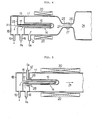
- an oxygen gas feeding apparatus comprises a combustion chamber I made of quarz, in the right head part of which are placed semiconductor wafers (not illustrated) aligned on a supporting board.
- An oxygen gas inlet tube 12 communicates with the combustion chamber I I and is connected to an oxygen gas supply (not illustrated).
- Numeral 13 denotes a hydrogen chamber 13, a part 14 of which projects into the combustion chamber II.
- a diaphragm 15 of the projecting part 14 is formed by a hydrogen permeable membrane or film of oxidation catalyst, which physically adsorps hydrogen gas on its surface and diffuses and transmits the hydrogen while uniformly distributing it all over the film surface.
- This film undertake catalysis at a temperature of 300 - 700 0 C, and generates steam by oxidising the hydrogen.
- a know palladium alloy may be used as the material of the hydrogen permeable film.
- Such a film of palladium alloy is made of palladium (Pd), Silver (Ag) and Gold (Au).
- the catalysts for hydrogen can be performed by Pd alone, but a film of Pd alone lacks strength, and therefore Ag and Au are added to enhance the strength.
- the thickness of the hydrogen permeable film is desirably as thin as possible, but it is usually formed not more than 0.5 mm in thickness considering strength on the other hand.
- the hydrogen chamber is connected to a hydrogen gas inlet pipe 16, which communicates with a hydrogen gas supply (not illustrated).
- the hydrogen chamber 13 also communicates with an exhaust chamber 18 by way of an inner pipe 17 inserted therein, and the exhaust chamber 18 is connected to an outlet pipe 19.
- An external heater 20 is disposed along the outer wall of the combustion chamber I to heat the hydrogen permeable film and the gas generated by reaction. It is also possible to dispose a plurality of projecting portions 14 of the hydrogen chamber 13 in the combustion chamber II ⁇
- the diaphragm 15 composed of the hydrogen permeable film is heated to a temperature of 300 - 700 0 C. Then oxygen gas is introduced from the oxygen gas supply to the combustion chamber I by way of oxygen gas inlet pipe 12. At this time, pressure in the combustion chamber I is no more than I kg/cm 2 . Under these conditions, hydrogen gas is introduced from the hydrogen gas supply source to the hydrogen gas chamber 13 through the hydrogen gas inlet pipe 16. The pressure of the introduced hydrogen gas is higher than the pressure within the combustion chamber I and is, for example, 10 kg/cm 2 .
- a part of the hydrogen gas introduced to the hydrogen gas chamber 13 passes through the diaphragm 15 and reaches the surface of the diagram on the combustion chamber side, where the hydrogen gas reacts with the excess of oxygen gas present in the combustion chamber to generate steam.
- the diaphragm 15 is heated itself by the oxidative reaction. Accordingly, if the quantity of hydrogen gas transmitted through the diaphragm 15 (in other words, the pressure of hydrogen gas supplied to the hydrogen gas chamber 13) is kept at a certain level, heating by the external heater 20 is not necessary since sufficient self-heating by oxidative reaction heat takes place.
- the palladium alloy has the property of refining (purifying) hydrogen as is well known and, even if the hydrogen gas supplied to the chamber 13 contains impurities, those impurities do not pass through the film but hydrogen alone is selectively transmitted.
- steam generated in the combustion chamber I is uniformly mixed with the excess of oxygen gas present in the chamber I I in the form of atmospheric gas and the mixture is sent in the direction 2) to the semiconductor wafer (not illustrated).
- the hydrogen gas not transmitted through the diaphragm 15 and the impurities are discharged from the outlet pipe 19 by way of the inner pipe 17 and exhaust chamber 18.
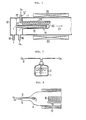
- FIGS 2 and 3 illustrate further respective embodiments of the invention which differ from the apparatus shown in Figure I in having heating means which are not external heaters but internal heaters 22, 23 inserted in the inner pipe 17 disposed in the hydrogen gas chamber 13.
- heating means which are not external heaters but internal heaters 22, 23 inserted in the inner pipe 17 disposed in the hydrogen gas chamber 13.
- the inner pipe 17 itself constitutes part of the heater.
- FIG. 4 shows a further embodiment of the invention, wherein a combustion chamber and a heat treatment chamber for semiconductor wafers are separated.
- the basic structure of the combustion chamber II' is not different from the embodiments described above, but the diameter of its free end is reduced to form a narrow neck portion 25.
- the diameter of an adjacent end of the semiconductor wafer heat treatment chamber 24 is also narrowed to form a neck portion 26 and the two chambers I I' and 24 are joined together by a connector 27 which couples their neck portions 25, 26 together.
- mixed gas composed of steam generated in the combustion chamber I I' and oxygen gas which is the atmospheric gas in the chamber II' flows to the heat treatment chamber 24 in the direction of the arrow 21', and during its passage through the narrowed neck portions 25, 26, the composition of the mixed gas becomes even and uniform.
- an external heater or an internal heater as shown in Figures I to 3 or, as shown in Figure 4, both an external heater 20 and an internal heater 23 may be used.
- FIGS 5 and 6 illustrate yet further respective embodiments of the invention respectively.
- a gas outlet opening 28 of the oxygen gas inlet pipe 12' is disposed around a base portion of the diaphragm 15, so that the oxygen gas introduced into the combustion chamber I from the oxygen gas induction pipe 12' flows along the surface of the diaphragm 15 and cools the diaphragm 15 to prevent it from being overheated by combustion of hydrogen gas.
- an oxygen gas inlet pipe 12' is extended into the combustion chamber II, and an extending pipe portion 29 thereof is disposed alongside the diaphragm.
- a plurality of gas outlets 30 are disposed so as to face the surface of the diaphragm 15.
Abstract
Description
- THE PRESENT INVENTION relates to apparatus for supplying oxygen gas containing uniformly distributed steam of high purity for use in a heat treatment process in which a heated wafer of semiconductor is fed with oxygen gas containing steam and the steam is deposited on the surface of the semiconductor wafer to form an oxide film thereon serving as a protective coat.
- Figure 7 of the accompanying drawings shows a known oxygen gas feeding apparatus employing a bubbling method. In this prior feeder, oxygen gas is blown into
pure water 2 stored in a sealed vessel I in the direction of the arrows in Figure 7, and the oxygen gas dampened by passing through thepure water 2 delivered to a treatment chamber (not shown). However, since a vessel or reservoir is used for the storage of the pure water, it is impossible with this known feeder to maintain the purity required in manufacturing semiconductor devices. Moreover, there is the drawback that the pure water in the vessel has to be changed or replenished often. - In order to meet such drawbacks, a so-called pyrogenic method is commonly used these days as shown in Figure 8. According to this method, oxygen gas is introduced into a
quarz tube 4, in whichsemiconductor wafers 8 are aligned on a supporting board 9, by way of an inlet pipe 5, while hydrogen gas is introduced into the oxygen gas atmosphere by way of an inlet pipe 6, and steam is generated by combustion of the hydrogen gas in the oxygen in thetube 4. The oxygen gas containing the generated steam that flows through thetube 4 and is deposited on the surface of the semiconductor wafers 8 to form an oxide film thereon. In Figure 8, numeral 7 denotes a hydrogen flame andnumeral 10 denotes a heater disposed along the outer wall of thequarz tube 4. - The aforementioned pyrogenic method indeed enables the purity required in the semiconductor manufacturing process to be maintained, but still has the following drawbacks:
- (I) It is hard to control the hydrogen flame, and there is the possibility of failure in ignition, which may cause an explosion.
- (2) The front end of the hydrogen flame may sometimes reaches the surface of the semiconductor wafer and damage it.
- (3) An uneven gas stream, in which only the downstream portion of the hydrogen flame has a high steam content may be generated, whereby the results of the solid surface treatment become non-uniform, particularly in the case of a semiconductor wafer of large diameter, lowering the quality of such wafer.
- Several attempts have been made to meet these drawbacks. According to one proposal, the quarz tube is elongated so as to put a larger distance between the hydrogen flame and the semiconductor wafer. According to Japanese Patent Publication (examined) Sho 59-53697, a nozzle of special design is proposed for the introduction of hydrogen gas. Further, as a method for achieving uniformity of hydrogen gas content, a separate combustion chamber system is employed wherein the combustion chamber is divided from the semiconductor heat treatment chamber, and the two chambers communicate with each other through a connector.
- Even when such a system of separate chambers is employed, the problem (I) above still remains unsolved, and moreover the inner wall surface of the combustion chamber is damaged by the hydrogen flame, resulting in the problem of further impurities in the gas.
- The invention aims enable solving of the aforesaid problems and, to this end, provides apparatus for supplying oxygen gas containing steam, comprising a hydrogen gas chamber and a combustion gas chamber separated by a hydrogen permeable membrane of oxidation catalyst, means for introducing oxygen gas into the combustion chamber and means for introducing hydrogen gas into the hydrogen chamber, so that the hydrogen gas diffuses through the catalytic membrane and reacts with the oxygen gas in the combustion chamber to generate steam.
- In apparatus embodying the invention part of the hydrogen gas induced into the hydrogen chamber is physically adsorpted onto the surface of the hydrogen permeable film of oxidation catalyzer, diffuses through the film uniformly over the surface of the film, and reacts with the excess of oxygen gas present on the opposite side of the film, i.e., in the combustion chamber, to generate steam. Since such oxidative combustion of hydrogen gas takes place as catalytic oxidation, the reaction proceeds gently but steadily at a relatively low temperature, and when the quantity of gas is small, there is no flame. Further, since the oxidation reaction occurs not locally but uniformly over the film, mixing of the steam generated by the reaction is also even. When the hydrogen permeable film is formed from a catalyst having a property of selectively passing the hydrogen gas alone, the film also provides purification of the hydrogen gas, resulting in hydrogen of high purity. A remaining part of the hydrogen gas which does not pass through the hydrogen permeable film and any impurities are exhausted from the hydrogen chamber through an exhaust tube as bleed gas.
- An oxygen gas feeder embodying the invention may provide the following advantages:
- ( I ) Since the combustion (i.e., oxidation) of the hydrogen gas takes place gently by catalytic reaction at a relatively low temperature, combustion control is relatively easy, and there is less possibility of ignition failure or danger of explosion.
- (2) In the combustion of the hydrogen gas, the combustion area is not spread to the extent of generating flame, and accordingly the semiconductor wafer is not damaged by the flame. When employing a separate combustion chamber system, there is no possibility of introducing impurities due to the hydrogen flame damaging the inner wall of the combustion chamber.
- (3) Since the combustion of hydrogen gas is evenly carried out all over the hydrogen permeable film of oxidation catalyst, the mixing of the generated steam with the oxygen gas (i.e., atmosphere gas) is also uniform and, as a result, even when treating a semiconductor wafer of large diameter, unfiorm and even surface treatment is applied all over the wafer surface enabling high quality thereof.
- (4) When the hydrogen permeable film is formed of a material having property of selectively transmitting the hydrogen gas alone, such as palladium alloy steam generated by the combustion of the hydrogen gas is also of high purity satisfying the purity required in semiconductor manufacturing processes.
- In order that the invention may be readily understood, an embodiment thereof will now be described, by way of example, with reference to the accompanying drawings, in which:
- Figure I is a front view of apparatus for supplying oxygen gas containing steam embodying the invention;
- Figures 2 to 6 are front views of several modified forms of apparatus embodying the invention; and
- Figures 7 to 8 are front views showing showing respective prior art apparatus.
- Referring to Figure I, an oxygen gas feeding apparatus comprises a combustion chamber I made of quarz, in the right head part of which are placed semiconductor wafers (not illustrated) aligned on a supporting board. An oxygen
gas inlet tube 12 communicates with the combustion chamber I I and is connected to an oxygen gas supply (not illustrated). - Numeral 13 denotes a
hydrogen chamber 13, apart 14 of which projects into the combustion chamber II. Adiaphragm 15 of the projectingpart 14 is formed by a hydrogen permeable membrane or film of oxidation catalyst, which physically adsorps hydrogen gas on its surface and diffuses and transmits the hydrogen while uniformly distributing it all over the film surface. This film undertake catalysis at a temperature of 300 - 7000C, and generates steam by oxidising the hydrogen. A know palladium alloy may be used as the material of the hydrogen permeable film. Such a film of palladium alloy is made of palladium (Pd), Silver (Ag) and Gold (Au). The catalysts for hydrogen can be performed by Pd alone, but a film of Pd alone lacks strength, and therefore Ag and Au are added to enhance the strength. The thickness of the hydrogen permeable film is desirably as thin as possible, but it is usually formed not more than 0.5 mm in thickness considering strength on the other hand. The hydrogen chamber is connected to a hydrogengas inlet pipe 16, which communicates with a hydrogen gas supply (not illustrated). Thehydrogen chamber 13 also communicates with anexhaust chamber 18 by way of aninner pipe 17 inserted therein, and theexhaust chamber 18 is connected to anoutlet pipe 19. Anexternal heater 20 is disposed along the outer wall of the combustion chamber I to heat the hydrogen permeable film and the gas generated by reaction. It is also possible to dispose a plurality of projectingportions 14 of thehydrogen chamber 13 in the combustion chamber II· - By arranging the apparatus as described above, the
diaphragm 15 composed of the hydrogen permeable film is heated to a temperature of 300 - 7000C. Then oxygen gas is introduced from the oxygen gas supply to the combustion chamber I by way of oxygengas inlet pipe 12. At this time, pressure in the combustion chamber I is no more than I kg/cm2. Under these conditions, hydrogen gas is introduced from the hydrogen gas supply source to thehydrogen gas chamber 13 through the hydrogengas inlet pipe 16. The pressure of the introduced hydrogen gas is higher than the pressure within the combustion chamber I and is, for example, 10 kg/cm2. Thus, a part of the hydrogen gas introduced to thehydrogen gas chamber 13 passes through thediaphragm 15 and reaches the surface of the diagram on the combustion chamber side, where the hydrogen gas reacts with the excess of oxygen gas present in the combustion chamber to generate steam. At this stage, thediaphragm 15 is heated itself by the oxidative reaction. Accordingly, if the quantity of hydrogen gas transmitted through the diaphragm 15 (in other words, the pressure of hydrogen gas supplied to the hydrogen gas chamber 13) is kept at a certain level, heating by theexternal heater 20 is not necessary since sufficient self-heating by oxidative reaction heat takes place. In addition, if a film of palladium alloy is used as the hydrogen permeable film, the palladium alloy has the property of refining (purifying) hydrogen as is well known and, even if the hydrogen gas supplied to thechamber 13 contains impurities, those impurities do not pass through the film but hydrogen alone is selectively transmitted. As a result, steam generated in the combustion chamber I is uniformly mixed with the excess of oxygen gas present in the chamber I I in the form of atmospheric gas and the mixture is sent in the direction 2) to the semiconductor wafer (not illustrated). In the meantime, the hydrogen gas not transmitted through thediaphragm 15 and the impurities are discharged from theoutlet pipe 19 by way of theinner pipe 17 andexhaust chamber 18. - Figures 2 and 3 illustrate further respective embodiments of the invention which differ from the apparatus shown in Figure I in having heating means which are not external heaters but
internal heaters inner pipe 17 disposed in thehydrogen gas chamber 13. In case of theinternal heater 23, theinner pipe 17 itself constitutes part of the heater. - In all of the embodiments described above with reference to Figures I to 3, the combustion chamber and the treatment chamber for receiving semiconductor wafers are formed as a common chamber. On the other hand, Figure 4 shows a further embodiment of the invention, wherein a combustion chamber and a heat treatment chamber for semiconductor wafers are separated. In such apparatus, the basic structure of the combustion chamber II' is not different from the embodiments described above, but the diameter of its free end is reduced to form a
narrow neck portion 25. Similarly, the diameter of an adjacent end of the semiconductor waferheat treatment chamber 24 is also narrowed to form aneck portion 26 and the two chambers I I' and 24 are joined together by aconnector 27 which couples theirneck portions heat treatment chamber 24 in the direction of the arrow 21', and during its passage through the narrowedneck portions external heater 20 and aninternal heater 23 may be used. - Figures 5 and 6 illustrate yet further respective embodiments of the invention respectively. In the apparatus shown in Figure 5, a gas outlet opening 28 of the oxygen gas inlet pipe 12' is disposed around a base portion of the
diaphragm 15, so that the oxygen gas introduced into the combustion chamber I from the oxygen gas induction pipe 12' flows along the surface of thediaphragm 15 and cools thediaphragm 15 to prevent it from being overheated by combustion of hydrogen gas. On the other hand, in the apparatus shown in Figure 6, an oxygen gas inlet pipe 12' is extended into the combustion chamber II, and an extendingpipe portion 29 thereof is disposed alongside the diaphragm. Further, a plurality ofgas outlets 30 are disposed so as to face the surface of thediaphragm 15. In the case of this apparatus, the oxygen gas fed to the combustion chamber II from the oxygengas inlet pipe 12" is blown out perpendicularly to the surface of thediaphragm 15 from thegas outlets 30, and as a result air cooling is carried out more effectively than in the apparatus of Figure 5. - The scope of the invention is not limited to the description above and the embodiments shown in the drawings. For example, various other oxidation catalysts can be formed into a thin hydrogen osmotic film for use in a feeder embodying the invention instead of a palladium alloy film, so far as their strength and performance are of a certain level.
- The features disclosed in the foregoing desription, in the following claims and/or in the accompanying drawings may, both separately and in any combination thereof, be material for realising the invention in diverse forms thereof.
Claims (10)
- (. Apparatus for supplying oxygen gas containing steam, comprising a hydrogen gas chamber and a combustion gas chamber separated by a hydrogen permeable membrane of oxidation catalyst, means for introducing oxygen gas into the combustion chamber and means for introducing hydrogen gas into the hydrogen chamber, so that the hydrogen gas diffuses through the catalytic membrane and reacts with the oxygen gas in the combustion chamber to generate steam.
- 2. Apparatus according to claim I, comprising an internal heater disposed in the hydrogen chamber.
- 3. Apparatus according to claim I, comprising an external heater disposed on the wall of the combustion chamber.
- 4. Apparatus according to any one of claims I to 3, wherein the combustion chamber and a treatment chamber for an object to be treated with the steam-containing oxygen gas are formed as a common chamber.
- 5. Apparatus according to any one of claims I to 3, wherein the combustion chamber and a treatment chamber for an object to be treated with the steam-containing oxygen gas are formed as separate interconnected chambers.
- 6. Apparatus according to any preceding claim, wherein an oxygen gas inlet tube connected to the combustion chamber has an outlet opening disposed adjacent the catalytic membrane.
- 7. Apparatus according to any preceding claim, wherein a part of the hydrogen chamber, defined by the hydrogen permeable catalytic membrane projects into the combustion chamber.
- 8. Apparatus according ot claim 7 as appendant to claim 6, wherein the outlet opening of the oxygen gas inlet tube encircles the projecting part of the hydrogen chamber.
- 9. Apparatus according to calim 7 as appendant to claim 6, wherein the oxygen gas inlet tube extends alongside the projecting part of the hydrogen chamber and has a plurality of outlet openings facing the catalytic membrane.
- 10. Apparatus according to any preceding claim, wherein the hydrogen permeable catalytic membrane comprises palladium.
Applications Claiming Priority (2)
| Application Number | Priority Date | Filing Date | Title |
|---|---|---|---|
| JP156708/85 | 1985-07-15 | ||
| JP60156708A JPS62104038A (en) | 1985-07-15 | 1985-07-15 | Steam-containing oxygen gas supplying device |
Publications (3)
| Publication Number | Publication Date |
|---|---|
| EP0209065A2 true EP0209065A2 (en) | 1987-01-21 |
| EP0209065A3 EP0209065A3 (en) | 1988-01-13 |
| EP0209065B1 EP0209065B1 (en) | 1990-11-07 |
Family
ID=15633597
Family Applications (1)
| Application Number | Title | Priority Date | Filing Date |
|---|---|---|---|
| EP86109328A Expired - Lifetime EP0209065B1 (en) | 1985-07-15 | 1986-07-08 | Method for supplying an oxygen gas containing steam for the surface treatment of semiconductor wafers |
Country Status (4)
| Country | Link |
|---|---|
| US (1) | US4693208A (en) |
| EP (1) | EP0209065B1 (en) |
| JP (1) | JPS62104038A (en) |
| DE (1) | DE3675444D1 (en) |
Cited By (4)
| Publication number | Priority date | Publication date | Assignee | Title |
|---|---|---|---|---|
| FR2643365A1 (en) * | 1989-02-22 | 1990-08-24 | Air Liquide | METHOD FOR METALLIZING CERAMICS AND APPARATUS FOR IMPLEMENTING IT |
| FR2643364A1 (en) * | 1989-02-22 | 1990-08-24 | Air Liquide | PROCESS FOR THE PREPARATION OF CERAMIC-METAL MULTILAYER COMPONENTS AND APPARATUS FOR IMPLEMENTING SAME |
| EP0922905A2 (en) * | 1997-12-10 | 1999-06-16 | Fujikin Inc. | Improvements in or relating to methods and apparatus for the generation of water vapour |
| KR100452159B1 (en) * | 2002-08-26 | 2004-10-12 | (주) 윈테크 | method for cleaning using catalyzer of semiconductor device and apparatus performing the same |
Families Citing this family (17)
| Publication number | Priority date | Publication date | Assignee | Title |
|---|---|---|---|---|
| JP2646990B2 (en) * | 1993-12-28 | 1997-08-27 | 日本電気株式会社 | Hydrogen reduction apparatus and method and hydrogen reduction material |
| KR100294984B1 (en) * | 1996-01-29 | 2001-09-17 | 오가와 슈우헤이 | A water generation method, a reaction furnace for generating water, a temperature control method of a reaction furnace for generating water, and a method of forming a platinum-coated catalyst layer |
| US6620723B1 (en) | 2000-06-27 | 2003-09-16 | Applied Materials, Inc. | Formation of boride barrier layers using chemisorption techniques |
| US6846516B2 (en) | 2002-04-08 | 2005-01-25 | Applied Materials, Inc. | Multiple precursor cyclical deposition system |
| US20030232501A1 (en) * | 2002-06-14 | 2003-12-18 | Kher Shreyas S. | Surface pre-treatment for enhancement of nucleation of high dielectric constant materials |
| US6858547B2 (en) | 2002-06-14 | 2005-02-22 | Applied Materials, Inc. | System and method for forming a gate dielectric |
| US20040198069A1 (en) | 2003-04-04 | 2004-10-07 | Applied Materials, Inc. | Method for hafnium nitride deposition |
| US20050252449A1 (en) | 2004-05-12 | 2005-11-17 | Nguyen Son T | Control of gas flow and delivery to suppress the formation of particles in an MOCVD/ALD system |
| US8119210B2 (en) | 2004-05-21 | 2012-02-21 | Applied Materials, Inc. | Formation of a silicon oxynitride layer on a high-k dielectric material |
| US8323754B2 (en) | 2004-05-21 | 2012-12-04 | Applied Materials, Inc. | Stabilization of high-k dielectric materials |
| US7402534B2 (en) | 2005-08-26 | 2008-07-22 | Applied Materials, Inc. | Pretreatment processes within a batch ALD reactor |
| US7798096B2 (en) | 2006-05-05 | 2010-09-21 | Applied Materials, Inc. | Plasma, UV and ion/neutral assisted ALD or CVD in a batch tool |
| US7659158B2 (en) | 2008-03-31 | 2010-02-09 | Applied Materials, Inc. | Atomic layer deposition processes for non-volatile memory devices |
| US8491967B2 (en) | 2008-09-08 | 2013-07-23 | Applied Materials, Inc. | In-situ chamber treatment and deposition process |
| US20100062149A1 (en) | 2008-09-08 | 2010-03-11 | Applied Materials, Inc. | Method for tuning a deposition rate during an atomic layer deposition process |
| DE102012219755A1 (en) * | 2012-10-29 | 2014-04-30 | Thyssenkrupp Marine Systems Gmbh | Method for generating water vapor |
| CN109441665A (en) * | 2018-12-26 | 2019-03-08 | 同济大学 | High-pressure gaseous hydrogen-oxygen jet engine device |
Citations (9)
| Publication number | Priority date | Publication date | Assignee | Title |
|---|---|---|---|---|
| GB1182062A (en) * | 1968-03-19 | 1970-02-25 | Carves Simon Ltd | Improvements in or relating to the Production of Controlled Quantities of Steam |
| USRE30145E (en) * | 1975-01-27 | 1979-11-13 | Unique Energy Systems, Inc. | Energy generating system |
| DE2831287A1 (en) * | 1978-07-17 | 1980-01-31 | Josef Hammer | Production of calibration gases with precise moisture content - using inert carrier with excess hydrogen or acetylene to which precise quantity of oxygen is added and mixt. passed over catalyst |
| JPS5718328A (en) * | 1980-07-09 | 1982-01-30 | Kinmon Seisakusho:Kk | H2o gas generating apparatus for oxidation of semiconductor wafer |
| JPS5740937A (en) * | 1980-08-22 | 1982-03-06 | Nec Home Electronics Ltd | Manufacture of semiconductor device |
| EP0069222A2 (en) * | 1981-05-27 | 1983-01-12 | Forschungszentrum Jülich Gmbh | Process for separating hydrogen and/or deuterium and tritium from a stream of inert gas, and device for performing this process in the gas cooling circuit of a gas-cooled nuclear reactor |
| US4377067A (en) * | 1980-11-24 | 1983-03-22 | Deutsche Forschungs- Und Versuchsanstalt Fur Luft- Und Raumfahrt | Steam generator |
| US4388892A (en) * | 1981-01-26 | 1983-06-21 | Rody Marc P N | Process and apparatus for generation of steam via catalytic combustion |
| EP0140073A2 (en) * | 1983-09-08 | 1985-05-08 | Forschungszentrum Jülich Gmbh | Permeable membrane for hydrogen |
Family Cites Families (2)
| Publication number | Priority date | Publication date | Assignee | Title |
|---|---|---|---|---|
| US4268538A (en) * | 1977-03-09 | 1981-05-19 | Atomel Corporation | High-pressure, high-temperature gaseous chemical method for silicon oxidation |
| JPS5953697A (en) * | 1982-09-21 | 1984-03-28 | Isuzu Motors Ltd | Method for coating cation type powder by electrodeposition |
-
1985
- 1985-07-15 JP JP60156708A patent/JPS62104038A/en active Pending
-
1986
- 1986-07-08 DE DE8686109328T patent/DE3675444D1/en not_active Expired - Lifetime
- 1986-07-08 EP EP86109328A patent/EP0209065B1/en not_active Expired - Lifetime
- 1986-07-15 US US06/885,697 patent/US4693208A/en not_active Expired - Fee Related
Patent Citations (9)
| Publication number | Priority date | Publication date | Assignee | Title |
|---|---|---|---|---|
| GB1182062A (en) * | 1968-03-19 | 1970-02-25 | Carves Simon Ltd | Improvements in or relating to the Production of Controlled Quantities of Steam |
| USRE30145E (en) * | 1975-01-27 | 1979-11-13 | Unique Energy Systems, Inc. | Energy generating system |
| DE2831287A1 (en) * | 1978-07-17 | 1980-01-31 | Josef Hammer | Production of calibration gases with precise moisture content - using inert carrier with excess hydrogen or acetylene to which precise quantity of oxygen is added and mixt. passed over catalyst |
| JPS5718328A (en) * | 1980-07-09 | 1982-01-30 | Kinmon Seisakusho:Kk | H2o gas generating apparatus for oxidation of semiconductor wafer |
| JPS5740937A (en) * | 1980-08-22 | 1982-03-06 | Nec Home Electronics Ltd | Manufacture of semiconductor device |
| US4377067A (en) * | 1980-11-24 | 1983-03-22 | Deutsche Forschungs- Und Versuchsanstalt Fur Luft- Und Raumfahrt | Steam generator |
| US4388892A (en) * | 1981-01-26 | 1983-06-21 | Rody Marc P N | Process and apparatus for generation of steam via catalytic combustion |
| EP0069222A2 (en) * | 1981-05-27 | 1983-01-12 | Forschungszentrum Jülich Gmbh | Process for separating hydrogen and/or deuterium and tritium from a stream of inert gas, and device for performing this process in the gas cooling circuit of a gas-cooled nuclear reactor |
| EP0140073A2 (en) * | 1983-09-08 | 1985-05-08 | Forschungszentrum Jülich Gmbh | Permeable membrane for hydrogen |
Non-Patent Citations (2)
| Title |
|---|
| PATENT ABSTRACTS OF JAPAN, vol. 6, no. 81 (E-107)[959], 19th May 1982; & JP-A-57 018 328 (KINMON SEISAKUSHO K.K.) 30-01-1982 * |
| PATENT ABSTRACTS OF JAPAN, vol. 6, no.111 (E-114)[989], 22nd July 1982; & JP-A-57 040 937 (SHIN NIPPON DENKI K.K.) 06-03-1982 * |
Cited By (9)
| Publication number | Priority date | Publication date | Assignee | Title |
|---|---|---|---|---|
| FR2643365A1 (en) * | 1989-02-22 | 1990-08-24 | Air Liquide | METHOD FOR METALLIZING CERAMICS AND APPARATUS FOR IMPLEMENTING IT |
| FR2643364A1 (en) * | 1989-02-22 | 1990-08-24 | Air Liquide | PROCESS FOR THE PREPARATION OF CERAMIC-METAL MULTILAYER COMPONENTS AND APPARATUS FOR IMPLEMENTING SAME |
| EP0384835A1 (en) * | 1989-02-22 | 1990-08-29 | L'air Liquide, Societe Anonyme Pour L'etude Et L'exploitation Des Procedes Georges Claude | Process for manufacturing multilayer metal-ceramic components, and apparatus therefor |
| EP0384834A1 (en) * | 1989-02-22 | 1990-08-29 | L'air Liquide, Societe Anonyme Pour L'etude Et L'exploitation Des Procedes Georges Claude | Process for the metallization of ceramics, and apparatus therefor |
| US5082606A (en) * | 1989-02-22 | 1992-01-21 | L'air Liquide, Societe Anonyme Pour L'etude Et L'exploitation Des Procedes Georges Claude | Process for producing ceramic-metal multilayer components and apparatus for carrying out the process |
| US5160765A (en) * | 1989-02-22 | 1992-11-03 | L'air Liquide, Societe Anonyme Pour L'etude Et L'exploitation Des Procedes Georges Claude | Process for the metallization of ceramics and apparatus for carrying out the process |
| EP0922905A2 (en) * | 1997-12-10 | 1999-06-16 | Fujikin Inc. | Improvements in or relating to methods and apparatus for the generation of water vapour |
| EP0922905A3 (en) * | 1997-12-10 | 2001-11-14 | Fujikin Inc. | Improvements in or relating to methods and apparatus for the generation of water vapour |
| KR100452159B1 (en) * | 2002-08-26 | 2004-10-12 | (주) 윈테크 | method for cleaning using catalyzer of semiconductor device and apparatus performing the same |
Also Published As
| Publication number | Publication date |
|---|---|
| EP0209065B1 (en) | 1990-11-07 |
| DE3675444D1 (en) | 1990-12-13 |
| US4693208A (en) | 1987-09-15 |
| JPS62104038A (en) | 1987-05-14 |
| EP0209065A3 (en) | 1988-01-13 |
Similar Documents
| Publication | Publication Date | Title |
|---|---|---|
| EP0209065B1 (en) | Method for supplying an oxygen gas containing steam for the surface treatment of semiconductor wafers | |
| US6733732B2 (en) | Reactor for generating moisture | |
| KR970060366A (en) | Devices for Purifying Barrel Reactors | |
| KR100281028B1 (en) | Method for Eliminating Nitrification During Preparation of Acrylonitrile | |
| TW423042B (en) | Apparatus for manufacturing semiconductor | |
| UA50853C2 (en) | Process heater of flameless combustion chamber and method for providing heat for endothermal process by means of such a heater | |
| RU2000112163A (en) | METHOD AND DEVICE FOR PREVENTING GLOBAL HEATING | |
| US5037293A (en) | Catalytic heater | |
| GB2197714A (en) | Gas burner | |
| EP0247384B1 (en) | Reformer | |
| MX9707573A (en) | Injector for scwo reactor. | |
| JP2005534156A (en) | Preferred oxidation reactor and process | |
| KR20000011647A (en) | Plant with high temperature fuel cells | |
| KR19990068003A (en) | Apparatus for producing heat treatment atmospheres | |
| US6961516B2 (en) | Steam generator and mixer using the same | |
| TR199701193T1 (en) | A process for the oxidation of ethylene in the catalytic vapor phase. | |
| JPS6022968B2 (en) | Method for catalytic reaction of reducing gases and high pressure reactor for carrying out this method | |
| JP4873282B2 (en) | Reforming method and reformer | |
| KR100474613B1 (en) | Method of Inductively Igniting a Chemical Reaction | |
| KR0153584B1 (en) | Furnace system equipped with protected combustion nozzle in fabrication of semiconductor device | |
| RU2703792C1 (en) | Internal combustion engine exhaust gases cleaning system | |
| JPH0373134B2 (en) | ||
| JPH07185253A (en) | Nitrogen gas supplying apparatus and its driving method and heating-in-nitrogen gas atmosphere apparatus using the apparatus | |
| GB2192624A (en) | Denitrating device for high temperature waste gas | |
| JPH0699059A (en) | Fluid bed device for chemical treatment of workpiece |
Legal Events
| Date | Code | Title | Description |
|---|---|---|---|
| PUAI | Public reference made under article 153(3) epc to a published international application that has entered the european phase |
Free format text: ORIGINAL CODE: 0009012 |
|
| AK | Designated contracting states |
Kind code of ref document: A2 Designated state(s): DE FR GB |
|
| PUAL | Search report despatched |
Free format text: ORIGINAL CODE: 0009013 |
|
| RHK1 | Main classification (correction) |
Ipc: C01B 5/00 |
|
| AK | Designated contracting states |
Kind code of ref document: A3 Designated state(s): DE FR GB |
|
| 17P | Request for examination filed |
Effective date: 19880319 |
|
| 17Q | First examination report despatched |
Effective date: 19890222 |
|
| GRAA | (expected) grant |
Free format text: ORIGINAL CODE: 0009210 |
|
| AK | Designated contracting states |
Kind code of ref document: B1 Designated state(s): DE FR GB |
|
| REF | Corresponds to: |
Ref document number: 3675444 Country of ref document: DE Date of ref document: 19901213 |
|
| ET | Fr: translation filed | ||
| PLBE | No opposition filed within time limit |
Free format text: ORIGINAL CODE: 0009261 |
|
| STAA | Information on the status of an ep patent application or granted ep patent |
Free format text: STATUS: NO OPPOSITION FILED WITHIN TIME LIMIT |
|
| 26N | No opposition filed | ||
| PGFP | Annual fee paid to national office [announced via postgrant information from national office to epo] |
Ref country code: GB Payment date: 19970630 Year of fee payment: 12 |
|
| PGFP | Annual fee paid to national office [announced via postgrant information from national office to epo] |
Ref country code: FR Payment date: 19970709 Year of fee payment: 12 |
|
| PGFP | Annual fee paid to national office [announced via postgrant information from national office to epo] |
Ref country code: DE Payment date: 19970714 Year of fee payment: 12 |
|
| PG25 | Lapsed in a contracting state [announced via postgrant information from national office to epo] |
Ref country code: GB Free format text: LAPSE BECAUSE OF NON-PAYMENT OF DUE FEES Effective date: 19980708 |
|
| GBPC | Gb: european patent ceased through non-payment of renewal fee |
Effective date: 19980708 |
|
| PG25 | Lapsed in a contracting state [announced via postgrant information from national office to epo] |
Ref country code: FR Free format text: LAPSE BECAUSE OF NON-PAYMENT OF DUE FEES Effective date: 19990331 |
|
| PG25 | Lapsed in a contracting state [announced via postgrant information from national office to epo] |
Ref country code: DE Free format text: LAPSE BECAUSE OF NON-PAYMENT OF DUE FEES Effective date: 19990501 |
|
| REG | Reference to a national code |
Ref country code: FR Ref legal event code: ST |