EP0191630A2 - Catheter with high speed drive means - Google Patents
Catheter with high speed drive means Download PDFInfo
- Publication number
- EP0191630A2 EP0191630A2 EP86300934A EP86300934A EP0191630A2 EP 0191630 A2 EP0191630 A2 EP 0191630A2 EP 86300934 A EP86300934 A EP 86300934A EP 86300934 A EP86300934 A EP 86300934A EP 0191630 A2 EP0191630 A2 EP 0191630A2
- Authority
- EP
- European Patent Office
- Prior art keywords
- catheter
- distal end
- drive means
- catheter according
- bearings
- Prior art date
- Legal status (The legal status is an assumption and is not a legal conclusion. Google has not performed a legal analysis and makes no representation as to the accuracy of the status listed.)
- Granted
Links
Images


Classifications
-
- A—HUMAN NECESSITIES
- A61—MEDICAL OR VETERINARY SCIENCE; HYGIENE
- A61B—DIAGNOSIS; SURGERY; IDENTIFICATION
- A61B17/00—Surgical instruments, devices or methods, e.g. tourniquets
- A61B17/32—Surgical cutting instruments
- A61B17/3205—Excision instruments
- A61B17/3207—Atherectomy devices working by cutting or abrading; Similar devices specially adapted for non-vascular obstructions
- A61B17/320758—Atherectomy devices working by cutting or abrading; Similar devices specially adapted for non-vascular obstructions with a rotating cutting instrument, e.g. motor driven
Definitions
- This invention relates to a recanalizing catheter for intravascular or other surgery.
- a catheter apparatus for recanalizing (opening) a passageway, e.g., an artery, which has been occluded by intra-arterial deposits of atherosclerotic plaque includes a multi-fluted, rotary cutting head mounted at the distal end of the catheter and arranged to be rotated by a flexible drive shaft extending through the catheter and powered by an electric motor at the proximal end thereof.
- the drive shaft is a steel helical coil approximately 1.3 mm in diameter. Such a coil is stated in the patent to be successful in transmitting high rotational speed (greater than 25,000 rpm) in a controlled fashion and with mechanical security.
- the catheter should be long, e.g., 66 to 100 cm or more, while its outside diameter, at least adjacent the working end, should be small, e.g., 3 to 4 mm.
- the catheter should be able to bend through a minimum diameter radius of curvature of about 7 mm or less, in order to reach small, remotely located restrictions, e.g., occlusions.
- the torsional shear stress produced on a flexible drive shaft (e.g., a wire) will differ for different wires, e.g., approximately 150,000 psi for steel wires, 70,000 psi for beryllium-copper wires. If the radius of curvature through which the drive shaft must bend is very small, e.g., less than 7 mm, high bending stresses will be induced therein. In order to reduce bending strain the diameter of the flexible drive shaft or wire must be made very small, e.g., 0.05 mm or-less.
- the invention provides a catheter for use in clearing an obstruction in a lumen in a living being, comprising an elongate flexible tubular member having a distal end at which is present a working tool and a proximal end at which is present a power means for driving the working tool, drive means extending through the tubular member for driving the tool, characterised in that centering means are present to enable the catheter to be bent through any arc up to a minimum radius of curvature while enabling the drive means to be rotated at high speed without causing excessive vibration.
- the centering means comprises bearing surfaces which support the drive means at longitudinally spaced locations therealong to maintain the drive means at a longitudinal neutral or central position within the catheter as the catheter is bent through any arc up to the minimum radius of curvature.
- the bearings have an opening therein forming a bearing surface through which the drive means extends, the bearings being arranged to pivot with respect to each other as the catheter is bent so that the drive shaft is maintained in the neutral position.
- spacers are present between adjacent bearings to maintain them a predetermined distance apart.
- the spacers Preferably have a pair of flared free ends to receive ball like bearings. It is preferred that the opening of the bearing is sufficiently short to provide adequate clearance for the drive means when the catheter is bent to the minimum radius of curvature.
- the distal end of the catheter includes a fixed bearing in which connector means is disposed, the connector means being secured to the distal end of the drive means and releasably connected to the tool.
- the centering means comprises a spiral of at least one wire wrapped about the other.
- the bearing means is formed as a spiral of a wire and the drive means is formed as a spiral of at least one wire in a helix.
- the invention includes a new items the flexible drive assemblies disclosed herein.
- the recanalizing catheter 1 is an elongate, flexible device having a distal end portion 2 at which a working head or tool 3 is present, and a proximal end portion 4, which is adapted to be connected to a rotary power source, e.g., an electric motor (not shown).
- the catheter includes a drive assembly 5 to rotate the head 3 under the power from the power source.
- the working head 3 comprises a rotary cutter 6 having a pair of convex sections 7 which are slightly laterally offset from each other along a divider line 8.
- the intersection of the convex surface 9 of each section 7 with a planar surface 10 contiguous with the divider line 8 forms an arcuate cutting edge or blade 11.
- the cutter may be made up of any number of sections, thereby having any number of arcuate blades, with each blade preferably including at least one portion having a negative or zero degree rake. In the embodiment shown each blade is at a negative rake angle of approximately 10°.
- the radial distance of the cutting edge 11 of each blade immediately adjacent the proximal face of the cutter, when measured from the longitudinal central axis 12, is slightly longer than the radial distance from that axis to the outside surface of the distal end portion of the catheter. This feature ensures that a slight space is created between the inner surface of the artery wall and the entrance to the interface 13 between the cutter 6 and the end of the catheter, to prevent any snagging or spooling action of the fibrous tissue of the artery wall within the interface.
- the catheter 1 comprises an elongate flexible tubular member 14 having a small outside diameter, e.g., 3 mm (10 French) or less and an inside diameter of approximately 1.8 mm.
- a sleeve 15 forming part of the mount for the cutter 6 is threaded by internal threads 16 to threads 17 on the distal end 2 of the catheter.
- a sleeve 18 is mounted within the sleeve 15 and supports a bearing 19 for rotation about axis 12.
- the bearing 19 is a cylinder within the bore of the sleeve 18 and serves as a releasable connector for connecting the cutter 6 to the distal end of the drive assembly 5.
- the bearing 19 includes a threaded bore 20 to engage a threaded short extension 21 projecting from the proximal face of the cutter 6 and on the central axis 12.
- the distal end of the drive assembly 5 includes drive shaft connector 22 which has an externally threaded, central short extension 23 which is also engaged in the bore 20 of the bearing 19.
- the sleeve 18 includes a pair of V-shaped grooves 24 extending longitudinally along the bearing.
- the grooves 24 are enclosed by the contiguous inner surface of the sleeve 15 to form a pair of diametrical fluid passageways for carrying the fluid from the interior of the catheter 1 to egress at the interface 13, as shown by the arrows in Figure 2.
- the drive assembly 5 comprises an elongate flexible drive shaft, which in the embodiment shown in Figures 1 to 7 is a length of a solid wire 25 of very small diameter, e.g. 0.5 mm or less and formed of a suitable high strength flexible material, e.g, steel.
- the wire 25 extends along the central axis 12 of the catheter.
- the distal end 26 of the wire 25 extends through a central opening 27 in the connector 22 and is bent perpendicular to be locked in a locking slot 28 so that rotation of the connector 22 about axis 12 causes the connector and wire to rotate together.
- the proximal end of the connector extension 23 comprises a rotor body 29 having a front wall 30, a rear wall 31, and a plurality of radial spokes or blades 32 projecting outward from a central hub 33 (Figure 5).
- the central opening 29 in the connector 27 extends through the hub 33 and includes an enlarged bore portion 34 ( Figure 2) which is in fluid communication with the spaces between the blades 32.
- Fluid to cool and lubricate the drive assembly is arranged to flow through the hollow interior of the catheter 1 past the drive assembly 5 and into the bore 34 from which it flows radially outward and into the proximal ends of the two V-shaped passageways 24, as shown by the arrows in Figure 2.
- Spaced apart bearings 35 support the wire 25 longitudinally centrally within the catheter to enable it to rotate at high speed without damage even when the catheter is bent through the very small (minimum) radius of curvature to be expected in intravascular surgical applications, while also precluding the wire from going into critical whirl i.e. excessive vibration as it is rotated at high speed.
- the bearings 35 are spaced apart by spacer elements 36 so that the centres of the bearings 35, that is the portions supporting the wire 25, are no further apart than one-half of the wavelength of the stationary or standing wave which would result from the rotation of an unsupported wire at the rotational speed.
- the spacing (pitch) of the bearings should be no larger than 0.64 cm and preferably 0.95 cm.
- each spacer 36 is an elongate tube having a pair of flared ends 37.
- Each bearing 35 is located between the trailing flared end 37 of one spacer and the leading flared end 37 of the adjacent spacer.
- a typical bearing 35 is shown in perspective in Figure 11, in elevation in Figure 1, and in section in Figure 2.
- the flared ends 37 of spacers 36 form a raceway or seat for the ball like bearings 35. Because ends of adjacent spacers are slightly separated from each other, the spacers can pivot with respect to each other about the intermediate bearing 35 when the catheter is bent, that is, the central longitudinal axis of each of any two immediately adjacent spacers will extend at an angle to the other instead of being colinear as is shown in Figure 2.
- Each of the bearings 35 includes a pair of flat end walls 38 connected by a central passageway 39 and perpendicular to the axis 12.
- the ends of the passageway 39 are slightly greater in diameter than the intermediate portion to form a bearing surface 40 which has a diameter just slightly larger than the diameter of the wire 25 to support the wire centrally.
- Each surface 40 forms a flex point for the wire 25 to enable the catheter to be bent while maintaining the wire centrally.
- Each bearing surface 40 is selected to be sufficiently short so that when the catheter is bent through the minimum radius of curvature, the portions of the bearing contiguous with the ends of the opening 39 do not interfere with the wire 25, while being long enough to provide sufficient surface area to accept the anticipated sideloads at the sliding velocities so that damage to the bearings does not occur.
- the length of the bearing surface 40 is no smaller than 1 mm.
- Each bearing 35 includes at least two diametrical side slots 41 ( Figures 6 and 11). Cooling and lubricating fluid introduced into a spacer 36 flows through the spacer, through the slots 41 and to the next spacer along the length of the catheter.
- an element 42 is present between the bearing adjacent the sleeve 18 and the nearest spacer 36 acts as a spacer and a bearing locator.
- the element 42 includes a tubular portion having a flared proximal end 43.
- the distal end of the element 42 includes an annular flanged portion 44 within the sleeve 15 and receives and holds the proximal end of the connector 22 and directs fluid from the rotor 29 into the grooves 24.
- the flanged portion 44 includes a sidewall opening 45 in alignment with a similar opening 46 in the sleeve 15.
- the aligned openings form a port for the insertion of a tool to lock or unlock the rotor 29 against rotation.
- the cutter 6 can be replaced by unscrewing it from the bearing 19.
- the catheter is introduced through an opening in the femoral artery at a point in the groin of the patient remote from the prelocated site of the vascular occlusion or blockage in an artery (e.g., a coronary artery).
- the catheter is passed via the aorta into the heart and then into the coronary artery until the working head is immediately adjacent the restriction, e.g., a partial occlusion or full occlusion formed by the deposit of atherosclerotic plaque or some other material(s), such as waxy and/or calcified atheroma, thickened and/or ilcerated intima, etc.
- the cutter 6 is arranged to be rotated at speed, e.g., in excess of 20,000 rpm, about the longitudinal central axis 12.
- rotating cutter blades 11 engage occluding material.
- an opening in the restriction is created by the blades cutting away or emulsifying particles of the material making up the restriction.
- Waxy or soft deposits may be mechanically agitated, beaten or otherwise disturbed by the blades to create an opening without such material(s) actually cut-up or removed from the restriction. In either case an opening permitting the flow of blood through the restriction results.
- the fluid to cool and lubricate the drive assembly also provides positive pressure to the wall of the artery contiguous with the cutter, thereby causing the artery wall to move slightly outward radially, away from the cutter, so that no damage to the artery wall by the cutter occurs.
- the rotating cutter blades impart momentum to the exiting fluid, which action applies further positive pressure to the artery wall, thereby further decreasing the chances of snagging of tissues.
- the flow of fluid through the interface 13 also precludes any fine fibrous tissue of the artery from gaining ingress into the interface where it could snag or accummulate.
- the fluid which is passed down the catheter can, if desired, be oxygenated to eliminate distal ischemia during the restriction opening procedure. Also if desired, nitrates, contrast medium or other drugs can be added to the fluid during the procedure.
- FIG 7 there is shown a catheter in which the drive assembly 5 includes a tubular or hollow wire drive shaft 25a and the cutter 6 includes a central opening 48 to enable a guidewire 49 to be passed therethrough to facilitate the placement of the recanalizing catheter at the desired site.
- the drive assembly 5 of Figure 7 has bearings 35 and spacers 36 which support a longitudinal central flexible drive shaft 47.
- the drive shaft wire 25a has a central passageway 50 extending the full length thereof.
- the introduction of the guidewire can be aided by a fluroscope, and a contrast medium can also be introduced into the artery.
- the recanalizing catheter of Figure 7 is threaded down the guidewire 49, via the opening 48 in the cutter 6 and the passageway 50 in the drive shaft to the restriction to be opened. The catheter is then operated as described above.
- the catheter 61 of Figures 12 to 15 comprises a head 62 having an outer generally convex surface 63 with four recesses 64 therein.
- the intersection of each of the walls of each recess 64 and the convex surface of the cutter forms an arcuate cutting edge or blade 65.
- Each arcuate blade 65 includes at least one surface portion having zero or negative rake, with the rake being preferably negative at an angle of approximately 10° to 30 0 .
- the cutter head 62 is arranged to be rotated at a speed, e.g., in excess of 20,000 rpm, about the longitudinal central axis 66 of the catheter under power provided from the remote power source, via the flexible drive assembly 5
- the catheter 61 comprises a flexible tubular member 67 which is formed of a suitable material, e.g., plastic, and which has a small outside diameter preferably approximately 3 mm (10 French) or less, and an inside diameter of approximately 1.5 mm (5 French).
- an outer bush 69 which forms part of the mount for the cutter head 62.
- the outer bush 69 comprises an elongate tubular body portion 70 having an annular flange 71 at the distal end 68.
- the flange portion 71 forms the distal end 68 of the catheter 61.
- the tubular body 70 has longitudinally spaced apart gripping teeth 72 and is held in place by a retaining band 73 which tightly encircles the catheter tube 67 to cause the teeth 73 to dig into the interior surface of the catheter tube 67.
- An inner bush 74 is fixed within the central passageway of the outer bush 69 and is also formed of a tough, wear resistant, low friction material, such as beryllium-copper.
- the inner bush 74 is an elongate sleeve having a central circular passageway 75.
- the outside wall of the inner bush 74 is generally circular in section but includes four, equadistantly spaced flat portions 76 ( Figure 14) which define four spaces 77 between it and the interior surface of the outer bush 69.
- Each space 77 is in communication with the open interface 78 between the cutting head 62 and the distal end 68 for reasons described below.
- a hollow mounting shaft 79 is located within the central bore 75 in the inner bush 74 and extends along the central axis 66 so that it can freely rotate within the inner bush about that axis.
- the shaft 79 includes a reduced diameter distal end 80 which is received in within a mating central bore 81 in the cutter head 62 which is secured to the mounting shaft 79 by a retainer pin 82 extending through aligned holes 83 and 84 in the shaft 72 and the cutter head 62, respectively, ( Figure 13).
- the shaft 79 has an annular flange 85 at its proximal end.
- a port 86 extends through the catheter tube 67 and an associated.port 87 is provided in the flanged portion 85 of the shaft 79.
- the ports can be aligned to receive a tool to lock the head 62 with respect to the catheter 61.
- the catheter 61 contains a flexible drive assembly 88 which comprises an elongate drive wire or shaft 89 which extends the length of the catheter from the power source to the shaft 79.
- the drive shaft 89 extends into the bore 90 of the shaft 79 and is secured therein.
- the drive shaft 89 is arranged to be rotated about the longitudinal axis 66 at high speed to rotate the cutter 62.
- the assembly 88 includes a bearing 91 to support and maintain the drive shaft 89 at a central (neutral) position within the catheter tube along its length, irrespective of bends in the catheter up to a minimum radius of curvature, e.g., 7.5 cm, while also preventing the drive shaft from going into critical whirl or undue vibration.
- the bearing member 91 comprises a helical or spiral cylindrical coil of wire surrounding the flexible drive shaft 89 and is formed of a flexible low friction material such as heat treated beryllium copper.
- the outer diameter of the bearing 91 is sufficiently great so that the loops just clear the interior surface 92 of the catheter tube 69 to hold the bearing 91 centered in place.
- the inside diameter of a central passageway 93 extending the length of the coil bearing 91 is just slightly greater than the outside diameter of the flexible drive shaft 89 so that the drive shaft 89 can rotate freely as shown by the arrows in Figure 15.
- the distal end 94 of the bearing 91 is connected to a stationary disc-like retaining wall 95 which is secured to the proximal end of the outer bush 69.
- the wall 95 includes a central opening 96 through which the flexible drive shaft 89 extends.
- the diameter of the opening 96 is sufficiently large to enable liquid introduced into the bore to flow through opening 96 into longitudinally extending passages to egress from the interface 78.
- the distal end 94 of the helical coil bearing 91 is secured to the wall 95 e.g. by welding.
- the helical bearing 91 surrounds the drive shaft 89 along its full length while keeping the drive shaft in the longitudinal centre of the catheter the drive shaft cannot go into critical whirl,be subject to undue vibration.
- the diameter of the wire making up the helical coil and the pitch of the coil loop and the pitch of the helical coil bearing 91 are selected to ensure that the catheter is sufficiently flexible to negotiate short radia of curvature, while not presenting an undue impediment to the flow of cooling fluid through the passageway 93 in the catheter.
- the diameter of the wire making up the helical coil is approximately 0.25 mm, and the pitch of each coil is approximately 45° which optimizes bending, flexibility, torsional strength and fluid flow passage. The shorter the pitch the more convolutions of the helix and hence the greater distance through which fluid must flow.
- the drive shaft is a single wire 89 but instead it can be a rope consisting of a central wire surrounded by six helical wires or a central tube surrounded by helical wires.
- the catheter 101 of Figures 16 to 19 includes a central passageway 93 through which a guide wire 49 can pass to facilitate the placement of the catheter at the desired position.
- the flexible drive assembly includes an elongated drive shaft, comprising a double helical coil having a longitudinally extending passageway for the guidewire.
- the head 62 of the catheter 101 is thread mounted, as opposed to being pin mounted like that of the embodiement of Figure 12.
- a shaft 102 is present within the central passageway 75 of the inner bush 74.
- the shaft 102 is a cylinder having a central passageway 103, the distal end 104 of which extends beyond the front face 105 of the outer bush 69.
- the projecting portion 104 includes peripheral helical threads 106.
- a matingly threaded bore 107 extends into the cutter 62 for threaded reception of the projecting portion 104 to mount the head 62 on the shaft.
- a central passageway 108 in the cutter head 62 is aligned with the passageway 103 and a guide wire 49 can be passed.
- the flexible drive shaft 5 comprises a pair of interlaced cylindrical helical (spiral) wires 109, 110 which form a passageway 93 about the guide wire 49 for substantially the length of the tube 61.
- the two helical wires are secured at the distal end to the flanged end 111 of the shaft 102 by suitable means, e.g., weld joints 112.
- Each of the wires 109 and 110 forming the flexible drive shaft 5 is of 0.25 mm outside diameter, with the pitch of each coil of the helix being approximately 45 0 .
- the inside diameter of the catheter tube and its outside diameter is the same as described with reference to Figure 12.
- the outside diameter of the flexible drive shaft 5 is slightly less than the inside diameter of the catheter tube to enable the drive shaft 5 to freely rotate about the central axis.
- the outside diameter of the passageway is just slightly greater than the outside diameter of guide wire 49 to enable the two spiral wires 109 and 110 making up the drive shaft 5 to rotate as a unit about the guide wire.
- the proximal end of the flexible drive shaft 5 is connected by means (not shown) to the electric motor (not shown) to effect such rotation and hence power the catheter 101.
- the guide wire 49 is centred in the catheter tube by the passageway 103 at the distal end and by centering means (not shown) at the proximal end thereof. Since the outer periphery of the coils 109, 110 making up the helical drive shaft are spaced slightly from the inner surface of the catheter tube the shaft 26 is enabled to rotate freely about the guide wire, while being centered within the catheter tube even when the tube is bent relatively sharp radia of curvature, e.g. 76 mm. Because the helical drive wires 109 and 110 are supported by the guide wire 49 along substantially the entire length thereof the drive shaft formed by those wires is precluded from going into critical whirl, irrespective of the speed of rotation.
- the rotation of the helical drive shaft 5 creates a pumping effect so that the cooling and lubricating liquid introduced into the interior of the tubular catheter at a proximal location is pumped down the length thereof.
- the catheter 101 in Figure 16 is guided to the operative position within the artery by the use of the guide wire 49.
- the catheter is then threaded down the guide wire via the opening 108 and 103 at the distal end thereof and through the central passageway extending down the helical drive shaft 26 until the tip 62 of the catheter is located immediately adjacent the proximal end of the restriction to be opened.
- a suitable liquid is then introduced into the interior of the catheter tube from a point adjacent the proximal end thereof to aid in lubricating and cooling the components within the catheter.
- the rotation of the helical coil drive shaft causes a pumping action on the liquid to flow down the catheter to the distal end.
- the liquid flows into communicating passages from whence it flows out of the open interface.
Abstract
Description
- This invention relates to a recanalizing catheter for intravascular or other surgery.
- In United States Patent No. 4,445,509 (Auth) there is disclosed a catheter apparatus for recanalizing (opening) a passageway, e.g., an artery, which has been occluded by intra-arterial deposits of atherosclerotic plaque. That recanalization catheter includes a multi-fluted, rotary cutting head mounted at the distal end of the catheter and arranged to be rotated by a flexible drive shaft extending through the catheter and powered by an electric motor at the proximal end thereof. The drive shaft is a steel helical coil approximately 1.3 mm in diameter. Such a coil is stated in the patent to be successful in transmitting high rotational speed (greater than 25,000 rpm) in a controlled fashion and with mechanical security.
- The catheter should be long, e.g., 66 to 100 cm or more, while its outside diameter, at least adjacent the working end, should be small, e.g., 3 to 4 mm. The catheter should be able to bend through a minimum diameter radius of curvature of about 7 mm or less, in order to reach small, remotely located restrictions, e.g., occlusions.
- The torsional shear stress produced on a flexible drive shaft (e.g., a wire) will differ for different wires, e.g., approximately 150,000 psi for steel wires, 70,000 psi for beryllium-copper wires. If the radius of curvature through which the drive shaft must bend is very small, e.g., less than 7 mm, high bending stresses will be induced therein. In order to reduce bending strain the diameter of the flexible drive shaft or wire must be made very small, e.g., 0.05 mm or-less. If the head is to be operated at a high speed, e.g., greater than 20,000 rpm to provide sufficient power at low torque, the deleterious dynamic effects of critical whirl and friction caused by high side loads in the bearing surfaces supporting the drive wire must be overcome or minimised otherwise the excessive vibration can cause damage. It is one object of this invention to provide a catheter as described and which can be operated at high speed without the risk of undesired side effects.
- In one aspect, the invention provides a catheter for use in clearing an obstruction in a lumen in a living being, comprising an elongate flexible tubular member having a distal end at which is present a working tool and a proximal end at which is present a power means for driving the working tool, drive means extending through the tubular member for driving the tool, characterised in that centering means are present to enable the catheter to be bent through any arc up to a minimum radius of curvature while enabling the drive means to be rotated at high speed without causing excessive vibration.
- In one preferred embodiment, the centering means comprises bearing surfaces which support the drive means at longitudinally spaced locations therealong to maintain the drive means at a longitudinal neutral or central position within the catheter as the catheter is bent through any arc up to the minimum radius of curvature. Preferably the bearings have an opening therein forming a bearing surface through which the drive means extends, the bearings being arranged to pivot with respect to each other as the catheter is bent so that the drive shaft is maintained in the neutral position.
- In a much preferred feature, spacers are present between adjacent bearings to maintain them a predetermined distance apart. Preferably the spacers have a pair of flared free ends to receive ball like bearings. It is preferred that the opening of the bearing is sufficiently short to provide adequate clearance for the drive means when the catheter is bent to the minimum radius of curvature.
- Preferably the distal end of the catheter includes a fixed bearing in which connector means is disposed, the connector means being secured to the distal end of the drive means and releasably connected to the tool.
- In another preferred embodiment the centering means comprises a spiral of at least one wire wrapped about the other. Preferably the bearing means is formed as a spiral of a wire and the drive means is formed as a spiral of at least one wire in a helix.
- The invention includes a new items the flexible drive assemblies disclosed herein.
- In order that this invention may be readily understood it will now be described with reference to the accompanying drawings wherein:
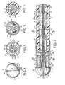
- Figure 1 is a side elevation partly in section, showing the distal end of one catheter device of the invention;
- Figure 2 is an enlarged sectional view taken along line II-II of Figure 1;
- Figure 3 is an end view of the catheter;
- Figure 4 is a sectional view taken along line IV-IV on Figure 2;
- Figure 5 is a sectional view taken along line V-V on Figure 2;
- Figure 6 is a sectional view taken along line VI-VI on Figure 2;
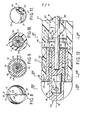
- Figure 7 is a sectional view of another catheter;
- Figure 8 is an end view of the catheter of Figure 7;
- Figure 9 is a sectional view taken along line IX-IX on Figure 7;
- Figure 10 is a sectional view taken along line X-X on Figure 7;
- Figure 11 is an enlarged perspective view of one bearing of the drive assembly;
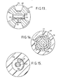
- Figure 12 is a side elevation partly in section showing the distal end of another catheter of this invention;
- Figure 13 is a sectional view taken along line XIII-XIII on Figure 12;
- Figure 14 is a sectional view taken along line XIV-XIV on Figure 12;
- Figure 15 is a sectional view taken along line XV-XV on Figure 12;
- Figure 16 is a side elevation view, partly in section, showing the distal end of another catheter of this invention;
- Figure 17 is a sectional view taken along line XVII-XVII on Figure 16;
- Figure 18 is a sectional view taken along line XVIII-XVIII of Figure 16 and
- Figure 19 is a sectional view taken along line XIX-XIX on Figure 16.
- The recanalizing catheter 1 is an elongate, flexible device having a distal end portion 2 at which a working head or
tool 3 is present, and aproximal end portion 4, which is adapted to be connected to a rotary power source, e.g., an electric motor (not shown). The catheter includes adrive assembly 5 to rotate thehead 3 under the power from the power source. - The working
head 3 comprises arotary cutter 6 having a pair ofconvex sections 7 which are slightly laterally offset from each other along adivider line 8. The intersection of theconvex surface 9 of eachsection 7 with aplanar surface 10 contiguous with thedivider line 8 forms an arcuate cutting edge orblade 11. The cutter may be made up of any number of sections, thereby having any number of arcuate blades, with each blade preferably including at least one portion having a negative or zero degree rake. In the embodiment shown each blade is at a negative rake angle of approximately 10°. - As can be seen in Figure 2 the radial distance of the
cutting edge 11 of each blade immediately adjacent the proximal face of the cutter, when measured from the longitudinalcentral axis 12, is slightly longer than the radial distance from that axis to the outside surface of the distal end portion of the catheter. This feature ensures that a slight space is created between the inner surface of the artery wall and the entrance to theinterface 13 between thecutter 6 and the end of the catheter, to prevent any snagging or spooling action of the fibrous tissue of the artery wall within the interface. - The catheter 1 comprises an elongate flexible
tubular member 14 having a small outside diameter, e.g., 3 mm (10 French) or less and an inside diameter of approximately 1.8 mm. At the distal end 2 of the catheter asleeve 15, forming part of the mount for thecutter 6 is threaded byinternal threads 16 tothreads 17 on the distal end 2 of the catheter. Asleeve 18 is mounted within thesleeve 15 and supports abearing 19 for rotation aboutaxis 12. Thebearing 19 is a cylinder within the bore of thesleeve 18 and serves as a releasable connector for connecting thecutter 6 to the distal end of thedrive assembly 5. Thebearing 19 includes a threadedbore 20 to engage a threadedshort extension 21 projecting from the proximal face of thecutter 6 and on thecentral axis 12. The distal end of thedrive assembly 5 includesdrive shaft connector 22 which has an externally threaded, centralshort extension 23 which is also engaged in thebore 20 of thebearing 19. - As can be seen in Figure 4, the
sleeve 18 includes a pair of V-shaped grooves 24 extending longitudinally along the bearing. Thegrooves 24 are enclosed by the contiguous inner surface of thesleeve 15 to form a pair of diametrical fluid passageways for carrying the fluid from the interior of the catheter 1 to egress at theinterface 13, as shown by the arrows in Figure 2. - The
drive assembly 5 comprises an elongate flexible drive shaft, which in the embodiment shown in Figures 1 to 7 is a length of asolid wire 25 of very small diameter, e.g. 0.5 mm or less and formed of a suitable high strength flexible material, e.g, steel. Thewire 25 extends along thecentral axis 12 of the catheter. Thedistal end 26 of thewire 25 extends through acentral opening 27 in theconnector 22 and is bent perpendicular to be locked in alocking slot 28 so that rotation of theconnector 22 aboutaxis 12 causes the connector and wire to rotate together. - As can be seen in Figures 2 and 5 the proximal end of the
connector extension 23 comprises arotor body 29 having afront wall 30, arear wall 31, and a plurality of radial spokes orblades 32 projecting outward from a central hub 33 (Figure 5). Thecentral opening 29 in theconnector 27 extends through thehub 33 and includes an enlarged bore portion 34 (Figure 2) which is in fluid communication with the spaces between theblades 32. - Fluid to cool and lubricate the drive assembly is arranged to flow through the hollow interior of the catheter 1 past the
drive assembly 5 and into thebore 34 from which it flows radially outward and into the proximal ends of the two V-shaped passageways 24, as shown by the arrows in Figure 2. - Spaced apart
bearings 35 support thewire 25 longitudinally centrally within the catheter to enable it to rotate at high speed without damage even when the catheter is bent through the very small (minimum) radius of curvature to be expected in intravascular surgical applications, while also precluding the wire from going into critical whirl i.e. excessive vibration as it is rotated at high speed. Thebearings 35 are spaced apart byspacer elements 36 so that the centres of thebearings 35, that is the portions supporting thewire 25, are no further apart than one-half of the wavelength of the stationary or standing wave which would result from the rotation of an unsupported wire at the rotational speed. In a preferred embodiment of the invention for wires of no larger than approximately 0.5 mm in diameter and which are to be rotated at speeds in excess of 20,000 rpm, the spacing (pitch) of the bearings should be no larger than 0.64 cm and preferably 0.95 cm. - As can be seen clearly in Figures 1 and 2, each
spacer 36 is an elongate tube having a pair of flared ends 37. Each bearing 35 is located between the trailing flaredend 37 of one spacer and the leading flaredend 37 of the adjacent spacer. Atypical bearing 35 is shown in perspective in Figure 11, in elevation in Figure 1, and in section in Figure 2. By their shape and disposition the flared ends 37 ofspacers 36 form a raceway or seat for the ball likebearings 35. Because ends of adjacent spacers are slightly separated from each other, the spacers can pivot with respect to each other about theintermediate bearing 35 when the catheter is bent, that is, the central longitudinal axis of each of any two immediately adjacent spacers will extend at an angle to the other instead of being colinear as is shown in Figure 2. The greatest deviation from colinearity that adjacent spacers can assume with respect to each other is a function of the geometry of the bearings and spacers, and, in the preferred embodiment disclosed herein, occurs when the catheter is bent through the minimum radius of curvature of 7.5 cm. At this point, edge portions of contiguous spacers abut to preclude further bending of the catheter. - Each of the
bearings 35 includes a pair offlat end walls 38 connected by acentral passageway 39 and perpendicular to theaxis 12. The ends of thepassageway 39 are slightly greater in diameter than the intermediate portion to form a bearingsurface 40 which has a diameter just slightly larger than the diameter of thewire 25 to support the wire centrally. Eachsurface 40 forms a flex point for thewire 25 to enable the catheter to be bent while maintaining the wire centrally. When the catheter is bent through an arc thespacers 36 pivot with respect to each other while thewire 25 bends about thepivot surface 40 in each bearing 35 but is generally straight and centred with respect to thespacer 36 through which it passes. Each bearingsurface 40 is selected to be sufficiently short so that when the catheter is bent through the minimum radius of curvature, the portions of the bearing contiguous with the ends of theopening 39 do not interfere with thewire 25, while being long enough to provide sufficient surface area to accept the anticipated sideloads at the sliding velocities so that damage to the bearings does not occur. In one preferred embodiment, the length of the bearingsurface 40 is no smaller than 1 mm. - Each bearing 35 includes at least two diametrical side slots 41 (Figures 6 and 11). Cooling and lubricating fluid introduced into a
spacer 36 flows through the spacer, through theslots 41 and to the next spacer along the length of the catheter. - As can be seen in Figure 2, an
element 42 is present between the bearing adjacent thesleeve 18 and thenearest spacer 36 acts as a spacer and a bearing locator. Theelement 42 includes a tubular portion having a flaredproximal end 43. The distal end of theelement 42 includes an annularflanged portion 44 within thesleeve 15 and receives and holds the proximal end of theconnector 22 and directs fluid from therotor 29 into thegrooves 24. - The
flanged portion 44 includes asidewall opening 45 in alignment with asimilar opening 46 in thesleeve 15. The aligned openings form a port for the insertion of a tool to lock or unlock therotor 29 against rotation. When theconnector 22 is locked in position, thecutter 6 can be replaced by unscrewing it from thebearing 19. - In use, the catheter is introduced through an opening in the femoral artery at a point in the groin of the patient remote from the prelocated site of the vascular occlusion or blockage in an artery (e.g., a coronary artery). The catheter is passed via the aorta into the heart and then into the coronary artery until the working head is immediately adjacent the restriction, e.g., a partial occlusion or full occlusion formed by the deposit of atherosclerotic plaque or some other material(s), such as waxy and/or calcified atheroma, thickened and/or ilcerated intima, etc.
- The
cutter 6 is arranged to be rotated at speed, e.g., in excess of 20,000 rpm, about the longitudinalcentral axis 12. In use, rotatingcutter blades 11 engage occluding material. In the case of hard or calcified deposits, an opening in the restriction is created by the blades cutting away or emulsifying particles of the material making up the restriction. Waxy or soft deposits may be mechanically agitated, beaten or otherwise disturbed by the blades to create an opening without such material(s) actually cut-up or removed from the restriction. In either case an opening permitting the flow of blood through the restriction results. - The fluid to cool and lubricate the drive assembly also provides positive pressure to the wall of the artery contiguous with the cutter, thereby causing the artery wall to move slightly outward radially, away from the cutter, so that no damage to the artery wall by the cutter occurs. The rotating cutter blades impart momentum to the exiting fluid, which action applies further positive pressure to the artery wall, thereby further decreasing the chances of snagging of tissues. The flow of fluid through the
interface 13 also precludes any fine fibrous tissue of the artery from gaining ingress into the interface where it could snag or accummulate. - The fluid which is passed down the catheter can, if desired, be oxygenated to eliminate distal ischemia during the restriction opening procedure. Also if desired, nitrates, contrast medium or other drugs can be added to the fluid during the procedure.
- In Figure 7 there is shown a catheter in which the
drive assembly 5 includes a tubular or hollowwire drive shaft 25a and thecutter 6 includes acentral opening 48 to enable aguidewire 49 to be passed therethrough to facilitate the placement of the recanalizing catheter at the desired site. Thedrive assembly 5 of Figure 7 hasbearings 35 andspacers 36 which support a longitudinal centralflexible drive shaft 47. Thedrive shaft wire 25a has acentral passageway 50 extending the full length thereof. The introduction of the guidewire can be aided by a fluroscope, and a contrast medium can also be introduced into the artery. The recanalizing catheter of Figure 7 is threaded down theguidewire 49, via theopening 48 in thecutter 6 and thepassageway 50 in the drive shaft to the restriction to be opened. The catheter is then operated as described above. - The catheter 61 of Figures 12 to 15 comprises a
head 62 having an outer generallyconvex surface 63 with fourrecesses 64 therein. The intersection of each of the walls of eachrecess 64 and the convex surface of the cutter forms an arcuate cutting edge orblade 65. Eacharcuate blade 65 includes at least one surface portion having zero or negative rake, with the rake being preferably negative at an angle of approximately 10° to 300. - The
cutter head 62 is arranged to be rotated at a speed, e.g., in excess of 20,000 rpm, about the longitudinalcentral axis 66 of the catheter under power provided from the remote power source, via theflexible drive assembly 5 - The catheter 61 comprises a
flexible tubular member 67 which is formed of a suitable material, e.g., plastic, and which has a small outside diameter preferably approximately 3 mm (10 French) or less, and an inside diameter of approximately 1.5 mm (5 French). At thedistal end 68 of thecatheter tube 67 there is secured anouter bush 69 which forms part of the mount for thecutter head 62. Theouter bush 69 comprises an elongate tubular body portion 70 having anannular flange 71 at thedistal end 68. Theflange portion 71 forms thedistal end 68 of the catheter 61. The tubular body 70 has longitudinally spaced apart grippingteeth 72 and is held in place by a retainingband 73 which tightly encircles thecatheter tube 67 to cause theteeth 73 to dig into the interior surface of thecatheter tube 67. Aninner bush 74 is fixed within the central passageway of theouter bush 69 and is also formed of a tough, wear resistant, low friction material, such as beryllium-copper. - As can be seen in Figures 12 and 14 the
inner bush 74 is an elongate sleeve having a centralcircular passageway 75. The outside wall of theinner bush 74 is generally circular in section but includes four, equadistantly spaced flat portions 76 (Figure 14) which define fourspaces 77 between it and the interior surface of theouter bush 69. Eachspace 77 is in communication with theopen interface 78 between the cuttinghead 62 and thedistal end 68 for reasons described below. - A hollow mounting
shaft 79 is located within thecentral bore 75 in theinner bush 74 and extends along thecentral axis 66 so that it can freely rotate within the inner bush about that axis. Theshaft 79 includes a reduced diameterdistal end 80 which is received in within a mating central bore 81 in thecutter head 62 which is secured to the mountingshaft 79 by aretainer pin 82 extending through alignedholes shaft 72 and thecutter head 62, respectively, (Figure 13). Theshaft 79 has anannular flange 85 at its proximal end. - A
port 86 extends through thecatheter tube 67 and anassociated.port 87 is provided in theflanged portion 85 of theshaft 79. The ports can be aligned to receive a tool to lock thehead 62 with respect to the catheter 61. - The catheter 61 contains a
flexible drive assembly 88 which comprises an elongate drive wire orshaft 89 which extends the length of the catheter from the power source to theshaft 79. Thedrive shaft 89 extends into thebore 90 of theshaft 79 and is secured therein. - The
drive shaft 89 is arranged to be rotated about thelongitudinal axis 66 at high speed to rotate thecutter 62. Theassembly 88 includes abearing 91 to support and maintain thedrive shaft 89 at a central (neutral) position within the catheter tube along its length, irrespective of bends in the catheter up to a minimum radius of curvature, e.g., 7.5 cm, while also preventing the drive shaft from going into critical whirl or undue vibration. - The bearing
member 91 comprises a helical or spiral cylindrical coil of wire surrounding theflexible drive shaft 89 and is formed of a flexible low friction material such as heat treated beryllium copper. - As can be seen in Figure 15, the outer diameter of the
bearing 91 is sufficiently great so that the loops just clear theinterior surface 92 of thecatheter tube 69 to hold thebearing 91 centered in place. The inside diameter of acentral passageway 93 extending the length of thecoil bearing 91 is just slightly greater than the outside diameter of theflexible drive shaft 89 so that thedrive shaft 89 can rotate freely as shown by the arrows in Figure 15. - As shown in Figure 12, the
distal end 94 of thebearing 91 is connected to a stationary disc-like retaining wall 95 which is secured to the proximal end of theouter bush 69. Thewall 95 includes acentral opening 96 through which theflexible drive shaft 89 extends. The diameter of theopening 96 is sufficiently large to enable liquid introduced into the bore to flow through opening 96 into longitudinally extending passages to egress from theinterface 78. Thedistal end 94 of thehelical coil bearing 91 is secured to thewall 95 e.g. by welding. - Because the
helical bearing 91 surrounds thedrive shaft 89 along its full length while keeping the drive shaft in the longitudinal centre of the catheter the drive shaft cannot go into critical whirl,be subject to undue vibration. - The diameter of the wire making up the helical coil and the pitch of the coil loop and the pitch of the
helical coil bearing 91 are selected to ensure that the catheter is sufficiently flexible to negotiate short radia of curvature, while not presenting an undue impediment to the flow of cooling fluid through thepassageway 93 in the catheter. In the embodiment shown the diameter of the wire making up the helical coil is approximately 0.25 mm, and the pitch of each coil is approximately 45° which optimizes bending, flexibility, torsional strength and fluid flow passage. The shorter the pitch the more convolutions of the helix and hence the greater distance through which fluid must flow. As shown the drive shaft is asingle wire 89 but instead it can be a rope consisting of a central wire surrounded by six helical wires or a central tube surrounded by helical wires. - The
catheter 101 of Figures 16 to 19 includes acentral passageway 93 through which aguide wire 49 can pass to facilitate the placement of the catheter at the desired position. The flexible drive assembly includes an elongated drive shaft, comprising a double helical coil having a longitudinally extending passageway for the guidewire. Thehead 62 of thecatheter 101 is thread mounted, as opposed to being pin mounted like that of the embodiement of Figure 12. - A
shaft 102 is present within thecentral passageway 75 of theinner bush 74. Theshaft 102 is a cylinder having acentral passageway 103, thedistal end 104 of which extends beyond the front face 105 of theouter bush 69. The projectingportion 104 includes peripheralhelical threads 106. A matingly threaded bore 107 extends into thecutter 62 for threaded reception of the projectingportion 104 to mount thehead 62 on the shaft. Acentral passageway 108 in thecutter head 62 is aligned with thepassageway 103 and aguide wire 49 can be passed. - The
flexible drive shaft 5 comprises a pair of interlaced cylindrical helical (spiral)wires passageway 93 about theguide wire 49 for substantially the length of the tube 61. The two helical wires are secured at the distal end to the flanged end 111 of theshaft 102 by suitable means, e.g., weld joints 112. - Each of the
wires flexible drive shaft 5 is of 0.25 mm outside diameter, with the pitch of each coil of the helix being approximately 450. 'The inside diameter of the catheter tube and its outside diameter is the same as described with reference to Figure 12. - The outside diameter of the
flexible drive shaft 5 is slightly less than the inside diameter of the catheter tube to enable thedrive shaft 5 to freely rotate about the central axis. - The outside diameter of the passageway is just slightly greater than the outside diameter of
guide wire 49 to enable the twospiral wires drive shaft 5 to rotate as a unit about the guide wire. The proximal end of theflexible drive shaft 5 is connected by means (not shown) to the electric motor (not shown) to effect such rotation and hence power thecatheter 101. - The
guide wire 49 is centred in the catheter tube by thepassageway 103 at the distal end and by centering means (not shown) at the proximal end thereof. Since the outer periphery of thecoils shaft 26 is enabled to rotate freely about the guide wire, while being centered within the catheter tube even when the tube is bent relatively sharp radia of curvature, e.g. 76 mm. Because thehelical drive wires guide wire 49 along substantially the entire length thereof the drive shaft formed by those wires is precluded from going into critical whirl, irrespective of the speed of rotation. - The rotation of the
helical drive shaft 5 creates a pumping effect so that the cooling and lubricating liquid introduced into the interior of the tubular catheter at a proximal location is pumped down the length thereof. - The
catheter 101 in Figure 16 is guided to the operative position within the artery by the use of theguide wire 49. The catheter is then threaded down the guide wire via theopening helical drive shaft 26 until thetip 62 of the catheter is located immediately adjacent the proximal end of the restriction to be opened. As in the other embodiment a suitable liquid is then introduced into the interior of the catheter tube from a point adjacent the proximal end thereof to aid in lubricating and cooling the components within the catheter. The rotation of the helical coil drive shaft causes a pumping action on the liquid to flow down the catheter to the distal end. The liquid flows into communicating passages from whence it flows out of the open interface.
Claims (13)
Priority Applications (1)
| Application Number | Priority Date | Filing Date | Title |
|---|---|---|---|
| AT86300934T ATE64081T1 (en) | 1985-02-13 | 1986-02-11 | HIGH SPEED DRIVE CATHETER. |
Applications Claiming Priority (4)
| Application Number | Priority Date | Filing Date | Title |
|---|---|---|---|
| US06/701,063 US4747406A (en) | 1985-02-13 | 1985-02-13 | Shaft driven, flexible intravascular recanalization catheter |
| US06/746,220 US4686982A (en) | 1985-06-19 | 1985-06-19 | Spiral wire bearing for rotating wire drive catheter |
| US746220 | 1985-06-19 | ||
| US701063 | 1996-08-21 |
Publications (3)
| Publication Number | Publication Date |
|---|---|
| EP0191630A2 true EP0191630A2 (en) | 1986-08-20 |
| EP0191630A3 EP0191630A3 (en) | 1987-12-23 |
| EP0191630B1 EP0191630B1 (en) | 1991-06-05 |
Family
ID=27106727
Family Applications (1)
| Application Number | Title | Priority Date | Filing Date |
|---|---|---|---|
| EP19860300934 Expired EP0191630B1 (en) | 1985-02-13 | 1986-02-11 | Catheter with high speed drive means |
Country Status (2)
| Country | Link |
|---|---|
| EP (1) | EP0191630B1 (en) |
| DE (1) | DE3679569D1 (en) |
Cited By (10)
| Publication number | Priority date | Publication date | Assignee | Title |
|---|---|---|---|---|
| WO1988002243A1 (en) | 1986-10-03 | 1988-04-07 | Intravascular Surgical Instruments, Inc. | Catheter with high speed moving working head for in-body surgical procedures |
| US4749376A (en) * | 1986-10-24 | 1988-06-07 | Intravascular Surgical Instruments, Inc. | Reciprocating working head catheter |
| AU598364B2 (en) * | 1987-10-23 | 1990-06-21 | Schneider-Shiley (Usa) Inc. | Atheroectomy catheter |
| AT391075B (en) * | 1988-09-21 | 1990-08-10 | Kaliman Josef | THROMBECTOMY CATHETER |
| FR2645009A1 (en) * | 1989-03-28 | 1990-10-05 | Honore Hugues | Device forming a probe for clearing a blood vessel, comprising percussion means |
| EP0398261A2 (en) * | 1989-05-17 | 1990-11-22 | Royce H. Husted | Powered microsurgical tool |
| US5269751A (en) * | 1988-09-21 | 1993-12-14 | Josef Kaliman | Thrombectomy catheter for enlarging an artery |
| EP0526042B1 (en) * | 1991-07-22 | 1998-05-13 | Dow Corning Enterprises | Catheter with improved fluid infusion |
| US6217595B1 (en) | 1996-11-18 | 2001-04-17 | Shturman Cardiology Systems, Inc. | Rotational atherectomy device |
| US8672921B2 (en) | 2006-03-15 | 2014-03-18 | Karl Storz Gmbh & Co. Kg | Flexible hollow shaft for a medical instrument |
Citations (1)
| Publication number | Priority date | Publication date | Assignee | Title |
|---|---|---|---|---|
| US4445509A (en) | 1982-02-04 | 1984-05-01 | Auth David C | Method and apparatus for removal of enclosed abnormal deposits |
Family Cites Families (5)
| Publication number | Priority date | Publication date | Assignee | Title |
|---|---|---|---|---|
| GB1235321A (en) * | 1968-01-30 | 1971-06-09 | Nat Res Dev | Improvements in or relating to drills for clearing obstructions |
| GB1356386A (en) * | 1970-06-03 | 1974-06-12 | Nat Res Dev | Artery entry tool |
| US4020847A (en) * | 1975-11-05 | 1977-05-03 | Clark Iii William T | Rotating cutter catheter |
| DE2933266A1 (en) * | 1979-08-16 | 1981-05-27 | Dietrich 8130 Starnberg Hasse | Ureter stone removal catheter - has shaft in hose with tool destroying stone at free end |
| EP0117519A1 (en) * | 1983-02-23 | 1984-09-05 | Johannes Dipl.-Ing. Theermann | Catheter |
-
1986
- 1986-02-11 DE DE8686300934T patent/DE3679569D1/en not_active Expired - Lifetime
- 1986-02-11 EP EP19860300934 patent/EP0191630B1/en not_active Expired
Patent Citations (1)
| Publication number | Priority date | Publication date | Assignee | Title |
|---|---|---|---|---|
| US4445509A (en) | 1982-02-04 | 1984-05-01 | Auth David C | Method and apparatus for removal of enclosed abnormal deposits |
Cited By (11)
| Publication number | Priority date | Publication date | Assignee | Title |
|---|---|---|---|---|
| WO1988002243A1 (en) | 1986-10-03 | 1988-04-07 | Intravascular Surgical Instruments, Inc. | Catheter with high speed moving working head for in-body surgical procedures |
| US4749376A (en) * | 1986-10-24 | 1988-06-07 | Intravascular Surgical Instruments, Inc. | Reciprocating working head catheter |
| AU598364B2 (en) * | 1987-10-23 | 1990-06-21 | Schneider-Shiley (Usa) Inc. | Atheroectomy catheter |
| AT391075B (en) * | 1988-09-21 | 1990-08-10 | Kaliman Josef | THROMBECTOMY CATHETER |
| US5269751A (en) * | 1988-09-21 | 1993-12-14 | Josef Kaliman | Thrombectomy catheter for enlarging an artery |
| FR2645009A1 (en) * | 1989-03-28 | 1990-10-05 | Honore Hugues | Device forming a probe for clearing a blood vessel, comprising percussion means |
| EP0398261A2 (en) * | 1989-05-17 | 1990-11-22 | Royce H. Husted | Powered microsurgical tool |
| EP0398261A3 (en) * | 1989-05-17 | 1991-09-11 | Royce H. Husted | Powered microsurgical tool |
| EP0526042B1 (en) * | 1991-07-22 | 1998-05-13 | Dow Corning Enterprises | Catheter with improved fluid infusion |
| US6217595B1 (en) | 1996-11-18 | 2001-04-17 | Shturman Cardiology Systems, Inc. | Rotational atherectomy device |
| US8672921B2 (en) | 2006-03-15 | 2014-03-18 | Karl Storz Gmbh & Co. Kg | Flexible hollow shaft for a medical instrument |
Also Published As
| Publication number | Publication date |
|---|---|
| EP0191630A3 (en) | 1987-12-23 |
| EP0191630B1 (en) | 1991-06-05 |
| DE3679569D1 (en) | 1991-07-11 |
Similar Documents
| Publication | Publication Date | Title |
|---|---|---|
| US4686982A (en) | Spiral wire bearing for rotating wire drive catheter | |
| US4747406A (en) | Shaft driven, flexible intravascular recanalization catheter | |
| US4681106A (en) | Catheter based surgical methods and apparatus therefor | |
| US5049124A (en) | Catheter drive apparatus having fluid delivery bearing | |
| EP0755227B1 (en) | Shaped wire multi-burr rotational ablation device | |
| US7344546B2 (en) | Intralumenal material removal using a cutting device for differential cutting | |
| US4749376A (en) | Reciprocating working head catheter | |
| US4842579A (en) | Atherectomy device | |
| EP0191630B1 (en) | Catheter with high speed drive means | |
| US6656195B2 (en) | Flexible inner tubular members and rotary tissue cutting instruments having flexible inner tubular members | |
| US6217595B1 (en) | Rotational atherectomy device | |
| CA2316240C (en) | Rotational atherectomy device with radially expandable prime mover coupling | |
| EP0347098B1 (en) | Atherectomy system with a guide-wire | |
| US4986807A (en) | Atherectomy cutter with radially projecting blade | |
| US11638624B2 (en) | Ultrasonic endovascular catheter with a controllable sheath | |
| EP2280657B1 (en) | Bidirectional expandable head for rotational atherectomy device | |
| KR20090037906A (en) | Atherectomy devices and methods | |
| EP1603486A2 (en) | Interventional catheters having differential cutting surfaces | |
| EP0335861B1 (en) | Catheter with high speed moving working head for in-body surgical procedures | |
| US20180110539A1 (en) | Devices, systems and methods for a piloting tip bushing for rotational atherectomy | |
| US9750525B2 (en) | Devices, systems and methods for an oscillating crown drive for rotational atherectomy | |
| JPS6168036A (en) | Tubular cavity passing type thrombosis removing apparatus | |
| EP3968876B1 (en) | Atherectomy devices including positive and negative rake angle cutting blades | |
| EP0663217B1 (en) | Rotating tip with shroud for catheter | |
| JP2024049865A (en) | Medical Devices |
Legal Events
| Date | Code | Title | Description |
|---|---|---|---|
| PUAI | Public reference made under article 153(3) epc to a published international application that has entered the european phase |
Free format text: ORIGINAL CODE: 0009012 |
|
| AK | Designated contracting states |
Kind code of ref document: A2 Designated state(s): AT BE CH DE FR GB IT LI LU NL SE |
|
| PUAL | Search report despatched |
Free format text: ORIGINAL CODE: 0009013 |
|
| AK | Designated contracting states |
Kind code of ref document: A3 Designated state(s): AT BE CH DE FR GB IT LI LU NL SE |
|
| 17P | Request for examination filed |
Effective date: 19880622 |
|
| RAP1 | Party data changed (applicant data changed or rights of an application transferred) |
Owner name: KENSEY NASH CORPORATION |
|
| RAP3 | Party data changed (applicant data changed or rights of an application transferred) |
Owner name: KENSEY NASH CORPORATION |
|
| 17Q | First examination report despatched |
Effective date: 19890919 |
|
| GRAA | (expected) grant |
Free format text: ORIGINAL CODE: 0009210 |
|
| AK | Designated contracting states |
Kind code of ref document: B1 Designated state(s): AT BE CH DE FR GB IT LI LU NL SE |
|
| PG25 | Lapsed in a contracting state [announced via postgrant information from national office to epo] |
Ref country code: SE Effective date: 19910605 Ref country code: NL Effective date: 19910605 Ref country code: LI Effective date: 19910605 Ref country code: CH Effective date: 19910605 Ref country code: BE Effective date: 19910605 Ref country code: AT Effective date: 19910605 |
|
| REF | Corresponds to: |
Ref document number: 64081 Country of ref document: AT Date of ref document: 19910615 Kind code of ref document: T |
|
| REF | Corresponds to: |
Ref document number: 3679569 Country of ref document: DE Date of ref document: 19910711 |
|
| ITF | It: translation for a ep patent filed |
Owner name: DR. ING. A. RACHELI & C. |
|
| REG | Reference to a national code |
Ref country code: CH Ref legal event code: PL |
|
| ET | Fr: translation filed | ||
| NLV1 | Nl: lapsed or annulled due to failure to fulfill the requirements of art. 29p and 29m of the patents act | ||
| PG25 | Lapsed in a contracting state [announced via postgrant information from national office to epo] |
Ref country code: LU Free format text: LAPSE BECAUSE OF NON-PAYMENT OF DUE FEES Effective date: 19920229 |
|
| PLBE | No opposition filed within time limit |
Free format text: ORIGINAL CODE: 0009261 |
|
| STAA | Information on the status of an ep patent application or granted ep patent |
Free format text: STATUS: NO OPPOSITION FILED WITHIN TIME LIMIT |
|
| 26N | No opposition filed | ||
| PGFP | Annual fee paid to national office [announced via postgrant information from national office to epo] |
Ref country code: GB Payment date: 19970206 Year of fee payment: 12 |
|
| PGFP | Annual fee paid to national office [announced via postgrant information from national office to epo] |
Ref country code: FR Payment date: 19970226 Year of fee payment: 12 |
|
| PGFP | Annual fee paid to national office [announced via postgrant information from national office to epo] |
Ref country code: DE Payment date: 19970414 Year of fee payment: 12 |
|
| PG25 | Lapsed in a contracting state [announced via postgrant information from national office to epo] |
Ref country code: GB Free format text: LAPSE BECAUSE OF NON-PAYMENT OF DUE FEES Effective date: 19980211 |
|
| PG25 | Lapsed in a contracting state [announced via postgrant information from national office to epo] |
Ref country code: FR Free format text: THE PATENT HAS BEEN ANNULLED BY A DECISION OF A NATIONAL AUTHORITY Effective date: 19980228 |
|
| GBPC | Gb: european patent ceased through non-payment of renewal fee |
Effective date: 19980211 |
|
| PG25 | Lapsed in a contracting state [announced via postgrant information from national office to epo] |
Ref country code: DE Free format text: LAPSE BECAUSE OF NON-PAYMENT OF DUE FEES Effective date: 19981103 |
|
| REG | Reference to a national code |
Ref country code: FR Ref legal event code: ST |
|
| PG25 | Lapsed in a contracting state [announced via postgrant information from national office to epo] |
Ref country code: IT Free format text: LAPSE BECAUSE OF NON-PAYMENT OF DUE FEES;WARNING: LAPSES OF ITALIAN PATENTS WITH EFFECTIVE DATE BEFORE 2007 MAY HAVE OCCURRED AT ANY TIME BEFORE 2007. THE CORRECT EFFECTIVE DATE MAY BE DIFFERENT FROM THE ONE RECORDED. Effective date: 20050211 |