EP0097763A2 - A method and apparatus for producing a DC balanced (0,4) run length limited rate 8B/10B code from an input data stream - Google Patents
A method and apparatus for producing a DC balanced (0,4) run length limited rate 8B/10B code from an input data stream Download PDFInfo
- Publication number
- EP0097763A2 EP0097763A2 EP83101758A EP83101758A EP0097763A2 EP 0097763 A2 EP0097763 A2 EP 0097763A2 EP 83101758 A EP83101758 A EP 83101758A EP 83101758 A EP83101758 A EP 83101758A EP 0097763 A2 EP0097763 A2 EP 0097763A2
- Authority
- EP
- European Patent Office
- Prior art keywords
- block
- sub
- bit
- disparity
- input
- Prior art date
- Legal status (The legal status is an assumption and is not a legal conclusion. Google has not performed a legal analysis and makes no representation as to the accuracy of the status listed.)
- Granted
Links
Images


Classifications
-
- H—ELECTRICITY
- H03—ELECTRONIC CIRCUITRY
- H03M—CODING; DECODING; CODE CONVERSION IN GENERAL
- H03M5/00—Conversion of the form of the representation of individual digits
- H03M5/02—Conversion to or from representation by pulses
- H03M5/04—Conversion to or from representation by pulses the pulses having two levels
- H03M5/14—Code representation, e.g. transition, for a given bit cell depending on the information in one or more adjacent bit cells, e.g. delay modulation code, double density code
- H03M5/145—Conversion to or from block codes or representations thereof
-
- H—ELECTRICITY
- H04—ELECTRIC COMMUNICATION TECHNIQUE
- H04L—TRANSMISSION OF DIGITAL INFORMATION, e.g. TELEGRAPHIC COMMUNICATION
- H04L25/00—Baseband systems
- H04L25/38—Synchronous or start-stop systems, e.g. for Baudot code
- H04L25/40—Transmitting circuits; Receiving circuits
- H04L25/49—Transmitting circuits; Receiving circuits using code conversion at the transmitter; using predistortion; using insertion of idle bits for obtaining a desired frequency spectrum; using three or more amplitude levels ; Baseband coding techniques specific to data transmission systems
- H04L25/4906—Transmitting circuits; Receiving circuits using code conversion at the transmitter; using predistortion; using insertion of idle bits for obtaining a desired frequency spectrum; using three or more amplitude levels ; Baseband coding techniques specific to data transmission systems using binary codes
- H04L25/4908—Transmitting circuits; Receiving circuits using code conversion at the transmitter; using predistortion; using insertion of idle bits for obtaining a desired frequency spectrum; using three or more amplitude levels ; Baseband coding techniques specific to data transmission systems using binary codes using mBnB codes
Definitions
- This invention relates to a method and apparatus for producing a DC balanced (0,4) run length limited rate 8B/10B code from an unconstrained input data stream.
- transmission codes The primary purpose of transmission codes is to transform the frequency spectrum of a serial data stream so that clocking can be recovered readily and AC coupling is possible.
- the code must also provide special characters outside the data alphabet for functions such as character synchronization, frame delimiters and perhaps for abort, reset, idle, diagnostics, etc. Codes are also used, often in combination with signal waveform shaping, to adapt the signal spectrum more closely to specific channel requirements. In most cases a reduction in bandwidth by constraints on both the high and the low frequency components is desirable to reduce distortion in the transmission media, especially electromagnetic cables, or in the band limited receiver, and to reduce the effects of extrinsic and intrinsic noise.
- Such codes generally exhibit the undesirable feature of enlarging error bursts in the decoded data, making detection by a cyclic redundancy check more difficult.
- a good transmission code should minimize these effects.
- the high gain fibre optic receivers need an AC coupling stage near the front end.
- the control of the drive level, receiver gain, and equalization is simplified and the precision of control is improved, if it can be based on the average signal power, especially at top rates.
- DC restore circuits tend to lose precision with rising data rates and cease to operate properly below the maximum rates for other circuits required in a transceiver.
- the time constants associated with the parasitic capacitances at the front end of a receiver are comparable to or longer than a baud interval, a signal with reduced low frequency content will suffer less distortion and will enable many links to operate without an equalizing circuit.
- the Manchester and related codes are simple two-level codes and solve the clocking and low frequency problems very well. They translate each bit into two bits for transmission and are a good choice whenever the high clocking rates cause no problems in the logic or analog circuits, the transducers or on the transmission line. They also reduce the data transmission rate by a factor of two since they encode 2 bits for every data bit (i.e., rate 1/2).
- Simple 5B/6B codes translate 5 binary bits into 6 binary digits and raise the number of information bits transmitted per baud interval to 0.833.
- the implementation of a 5B/6B code in a byte-oriented (8 bit) system causes burdensome complexities. If the encoding and decoding is done serially, most of the circuits needed have to operate at the baud rate, which sometimes is at the technology limits. Also, there is no simple relationship between the byte clock and the coder clock. Finally, if the frames are not multiples of 5 bytes, the character boundaries will not align with the frame boundaries, which is unattractive, whether corrected or not. If the coding and decoding is done in parallel, there is no simple mechanism to align a byte parallel interface with a 5B/6B coder; the most straightforward way requires shift registers operating at the baud rate.
- U. S. Patent 3,798,635 discloses an 8 bit to 12 bit code expansion system. It does not disclose the present system's dc balanced run length limited codes.
- U. S. Patent No. 3,577,142 discloses a system for translating a 12 bit code into a 8 bit code and is cited as background but does not relate to the present run length limited coding systems.
- U. S. Patent No. 3,594,560 discloses a simple expander for precompressed data and is similar to the two patents cited above representatives of the state of the art and is not otherwise related to run length limited coding systems.
- a method for producing a DC balanced (0,4) run length limited rate 8B/IOB code from an unconstrained input data stream comprising a multiplicity of 8 bit data blocks characterised in that said method includes partitioning the 8 bit block into two sub-blocks consisting of 5 and 3 contiguous bits, examining (12, 14) each sub-block to determine if any of the individual bits require alteration and altering predetermined bits based on said determination to produce an alternate code pattern, determining (16) the disparity (DO) of the current output sub-block being coded, ascertaining (16) the disparity (D-1) of the last non-zero sub-block coded and selecting a first code pattern as the current output sub-block for certain of the output. sub-blocks if the last non-zero disparity in the output code pattern was of a first polarity and assigning (18) the complement of said first code pattern if the last non-zero disparity was of the opposite polarity.
- a binary data encoding apparatus for producing a DC balanced (0,4) run length limited rate 8B/IOB code from an unconstrained input data stream characterised in that the apparatus includes means for supplying consecutive 8 bit data blocks to said apparatus, means for partitioning the 8 bit input block into two sub-blocks consisting of 5 and 3 contiguous bits, means (12, 14) for testing each input sub-block to determine if any of the individual bits require alteration during encoding and altering predetermined bits based on said determination to produce an alternate code pattern from said input bit pattern, means (16) for determining the disparity (DO) of the current output sub-block being coded, means (16) for determining the disparity (D-1) of the last non-zero sub-block coded and generating a first code pattern as the current output sub-block for certain of the output sub-blocks if the last non-zero disparity sub-block in the output code stream was of a first polarity and means (18) for generating the complement of said first code pattern if the
- the code produced by the present invention is DC balanced and capable of operating near the theoretical performance limits for an 8B/10B code. This means the code is near optimum for run length and digital sum variation for an 8B/10B code.
- Each 8 bit input block is broken into a 5 bit and a 3 bit sub-block and encoded separately while maintaining both DC balance and runlength constraints across all block and sub-block boundaries.
- the coding hardware performs bit encoding, disparity, and complementation determinations in parallel to minimize encoding time and logic levels.
- a plurality of special purpose control characters such as commas, delimiters, idle characters, etc. by using the extra bits in the coded blocks whereby the special characters may be readily distinguished from data, while at the same time maintaining the DC balance and run length limitations in such characters.
- the stream of signals transmitted down a channel must be constrained so that enough transitions for timing recovery and little or no DC spectral components are present.
- DSV digital sum variation
- run length is defined as the number of identical contiguous symbols which appear in the signal stream.
- the run length is the number of contiguous ones or zeros after encoding.
- What is of interest is the shortest (X) and the longest (Y) run lengths that appear.
- the (d,k) representation gives the minimum (d) and maximum (k) number of bauds between unequal symbols.
- any symbol can be followed by no more than 3 contiguous identical symbols, for a maximum run length of 4.
- Codes designed for digital transmission usually have a parameter d of zero.
- the preferred codes for magnetic recording on the other hand, have usually a parameter value d of 1 or greater, i.e., the minimum spacing between transitions is longer than a baud interval.
- a basic principle embodied in the present invention is the partitioned block format. Due to reasons connected with error propagation, it is desirable to encode 8 bits at a time in code words of 10 bits to be transmitted, rather than 4 into 5. However, a nonlinear encoding of eight bits such as that described here presents difficulties in implementation, as well as the likelihood that a single error in detection will result in eight erroneously decoded data bits. These problems are solved via the partitioned block format: that is, the eight bits are encoded using coders producing less than 10 bit outputs. These coders interact so as to yield the desired code words. The result is a coder whose coding rate, complexity and error propagation are near the theoretical limits, and which has ancillary benefits in flexibility of adaptation to various situations. Other partitions beside the 5/6, 3/4 were considered in the design proven, but all appear to have disadvantages in error propagation and other criteria.
- the code is near the theoretical limits in terms of the commonly used criteria of Digital Sum Variation and maximum run length. Beyond the 256 code points needed for the encoding of a byte of data, the code, as disclosed contains also 3 synchronizing and 9 other special characters for use as frame delimiters and other control functions. If one includes the 12 special characters, the coding efficiency amounts to 0.8066 bits per baud:
- the encoder implementation assumes a parallel byte wide interface for data.
- a serial implementation is possible; however, this code is primarily intended for links operating at or above a few Mbit/sec, where there is incentive to minimize the number of logic circuits operating at the baud rate and to separate out as many lower speed circuits as possible for implementation in a denser, lower cost technology.
- the encoder and decoder circuits operate at the byte rate.
- FIG. 1 the overall functional organization of the encoder of the present invention is shown.
- the FIGURE also represents in essence a data flow chart for the encoding system. It is assumed that 8 bit bytes of parallel data enter the adaptor interface 10 at the top. It will be well understood that the data could be provided on parallel lines from an originating system or could be the output of a serial to parallel converter which accumulates data in 8 bit blocks and transfers it to the adaptor interface 10 in parallel.
- the 8 input data bits are clearly shown as ABCDE and FGH. Control bit K as shown will indicate special characters.
- the first 5 data bits ABCDE are gated into the logical function encoder 12 for the 5 bit sub-block and bits FGH are gated to functional encoder 14 for the 3 bit sub-block.
- the logical functions these blocks perform is set forth in the "classification" column of Table I labelled "bit encoding.”
- the disparity control 16 performs the logical determinations specified in the "disparity” classification column of Table I.
- a description of the logical operations and circuitry for performing the 'bit encoding,' the 'disparity' determinations and the complementation decisions will be set forth more fully subsequently.
- the communications Adapter interface 10 consists of the 8 data lines ABCDEFGH (note the upper case notation), a control line K, and a clock line CLK operating at the byte rate.
- the control line K indicates whether the lines A through H represent data or control information such as frame delimiters and a limited set of other special characters.
- each incoming byte is partitioned into two sub-blocks.
- the 5 binary lines ABCDE (see FIG. 1) are encoded into the 6 binary lines abcdei (note the lower case notation), following the directions of the 5B/6B logic functions and the disparity control.
- the three bits FGH are encoded into fghj.
- the 5B/6B and 3B/4B encoders operate to a large extent independently of each other.
- the disparity of a block of a data is the difference between the number of ones and zeros in the block; positive and negative disparity numbers refer to an excess of ones or zeros respectively.
- the permitted disparity is either zero or +2 or -2.
- a 6B sub-block containing 4 ones and 2 zeros has a disparity of +2.
- the coding rules require that the polarity of non-zero disparity blocks must alternate. For this purpose, there is no distinction made between 6B and 4B sub-blocks.
- Non-zero disparity code points are assigned in complementary pairs to a single data point.
- the encoding functions generate one of them; if it violates the alternating polarity rule, the complete sub-block is inverted in the encoding switch to conform with the required disparity.
- Disparity and polarity determination in the 6B encoder is followed by the corresponding operations of the 4B encoder, then the running disparity parameter is passed along for encoding of the next byte.
- the majority of the coded sub-blocks are of zero disparity and are, with some exceptions, independent of the running disparity, i.e., they do not have a complementary alternate since they don't need one.
- the 10 encoded lines abcdeifghj would normally interface with a serializer for subsequent transmission.
- the a' bit must be transmitted first and 'j' last.
- the 8B/10B encoding is accomplished by encoding the bits ABCDE of the input byte into the line digits abcdei in a 5B/6B encoder following the coding plan and rules specified Table I, and the bits FGH in a 3B/4B encoder into the line digits fghj following the rules of Table II.
- the entry L04 means that there are no ones but 4 zeros in ABCD; L13 means that there is I one and 3 zeros in ABCD, etc.
- the letter L indicates that this logic function or classification is part of the 5B/6B encoder.
- Analogous functions are defined for the 6B/5B decoder in Table IV and labelled P. An accent to the right of a symbol is used to represent complementation; thus E' means the complement of E.
- the column D-1 indicates the required running disparity for entry of the adjacent sub-block to the right (i.e., the next sub-block to be coded).
- An x in the D-1 column means that D-1 can be + or -. Stated differently the disparity of the current sub-block is zero. In this code the polarity of the running disparity at sub-block boundaries is identical to the polarity of the most recent non-zero disparity block.
- the DO column indicates the disparity of the encoded sub-block to the left (the sub-block being coded), which is either 0, +2 or -2.
- the disparities (i.e., columns D-1 and D0) for the "alternate" code points on the right side of Table I and II are exact complements of those to their left and arc not shown in the Tables.
- the encoder hardware determines directly from the ABCDE and K inputs the disparities of a sub-block without really counting ones and zeros.
- the respective logic functions performed for classification of code words in terms of disparity requirements are shown in the separate column in Table I marked "Disparity.”
- Table I line D.7, a pair of zero disparity 6B sub-blocks is assigned to a single data point with an entry disparity constraint similar to those applicable to non-zero disparity sub-blocks.
- This coding feature reduces the maximum digital sum variation from 8 to 6 and, combined with an analogue rule in the 3B/4B encoder for D/K.x.3 of Table II, (explained further subsequently), eliminates all sequences of run length 6 and most of those with run length 5.
- the technique oi assigning a pair of complementary zero disparity sub-blocks to a single code point is also used uniformly for all 4B sub-blocks which are part of a special character as shown in Tables II and III for the special characters desiynated as K.28.1, K.28.2, K.28.3, K.28.5 and K.28.6.
- Table II follows the conventions and notations of Table 1. In Table II some lines have 2 entries in the column for the classification of disparity; the left classification refers to the entry disparity D-1 and the right one to D0.
- D.x.P7 Primary 7
- D/K.y.A7 Alternate 7
- the D/K.y.A7 code point was introduced to eliminate the run length 5 sequence in digits eifgh.
- the A7 code replaces the P7 encoding whenever:
- the D/K.y.A7 encoding can generate a run length 5 sequence across the trailing character boundary in the ghjab bits; however, this sequence is preceded by a run length of only I in digit f, with one exception: If the leading character is the special character K.28.7, a run length 5 sequence across the trailing character boundary is preceded by another run length 5 sequence in cdeif. For the significance of these distinctions see the following discussion of special characters.
- the zero-disparity 4B sub-blocks of K. 28.1, K.28.2, K.28.5 and K.28.6 are handled similarly to D/K.x.3 with respect to complementation in order to generate some special characters with byte synchronizing or comma properties.
- the first number (28) is the decimal equivalent for abcde, the second number is for the decimal equivalent of bits fgh, x is for don't cares.
- Special characters are defined here as extra code points beyond the 256 needed to encode a byte of data. They can exist because of the 2 extra bits inserted by the encoding process (i.e. , 8 bits expanded to 10 bits).
- the set of 12 special characters shown in Table III can be generated by the coding rules defined in Table I and II. This set of special characters includes the most useful ones from a larger set which could be defined, if needed. They all comply with the general coding constraints of a maximum run length of 5 and a maximum digital sum variation of 6.
- a comma indicates the proper byte boundaries and can be used for instantaneous acquisition or verification of byte synchronization.
- the comma sequence must be singular and occur with a uniform alignment relative to the byte boundaries; in the absence of errors the comma must not occur in any other bit positions neither within characters nor through overlap between characters.
- Three characters in this code (K.28.1, K.28.5, K28.7) have comma properties; they are marked with an asterisk in Table III and the singular sequence is printed in bold type. These three characters are also the most suitable delimiters to mark the start and end of a frame.
- the singular comma in this code is a sequence of run lengt 2 or w more ending with digit b followed by a run length 5 sequence; where this second sequence is not permitted to be the RL>2 sequence of another comma; in other words, if two or more RL>2/RL5 sequences overlap, only the first, third or any odd numbered one is recognized as a comma. This rule is necessary, because in some situations the K.28.7 comma is followed by another run length 5 sequence in digits ghjab.
- the K.28.7 comma is often preferred over the other two, because in the synchronized state no single error can generate a valid K.28.7 from data.
- the frame structure To get the same level of immunity from noise with the other two commas one can define the frame structure so the delimiters are always followed by a 6B sub-block with non-zero disparity.
- the parameters used in the present description to describe the spectral properties of the code are the digital sum variation, the disparity, and the run length.
- the maximum DSV between arbitrary points in this code is 6. Sometimes the DSV is quoted with reference to specific bit positions, such as the end of a character, and a lower figure usually results. For the code described here the maximum DSV between any two i/f or j/a bit boundaries is 2.
- disparity is used here to designate the excess of one bits over zero bits in a defined block of digits or the instantaneous deviation from the long-term average value of the running digital sum.
- All 6B and 4B sub-blocks individually and the complete 10-baud characters have a disparity of either 0 or +2, i.e., each valid character in the 10B alphabet has either 5 ones and 5 zeros, or 6 ones and 4 zeros, or 4 ones and 6 zeros.
- FIG. 2 also reveals some of the dynamics of the disparity parameter, i.e., how long it can remain at extreme values.
- the disparity of this code cannot exceed 121 for longer than 2 baud intervals; similarly, it cannot remain above
- the disparity can remain non-zero for the duration of a complete frame minus 10 baud intervals. It is readily seen from FIG. 2 just what the necessary conditions for this are. If, for example, the data portion of the frame starts with a Disparity of +1 and throughout the frame the disparity will not return to zero until the ending delimiter; the delimiters as described in 3.2.3.1 all contain at least one nonzero-disparity sub-block and cross the zero disparity line in the centre of the character between the e and i bits, as shown by the bold lines.
- the dynamics of the disparity parameter are relevant to the design of the AC circuits associated with the transmitter and receiver.
- the run length was defined previously, as the number of contiguous identical symbols; since the code at hand is a binary or two-level code, the run length is simply the number of contiguous ones or zeros after encoding. What is of interest is the shortest and the longest run length, which are one and five in this code.
- FIG. 2 also shows, which bit positions could potentially be part of a run length 5 sequence.
- Potential RL 5 sequences start with bit positions c, e, g and j.
- the inherent redundancy of the code can be used for error detection. Errors in the line digits will often generate invalid characters or violations of the disparity rules. Simple circuits (not shown in this application) can monitor for such irregularities. Generally, whenever the number of erroneous ones in the line digits of a frame is not equal to the number of erroneous zeros, it will be detected as a code violation and in many of the other cases as well.
- a CRC can generally detect any single error burst of a length, which does not exceed the number of check bits.
- any single error burst in the encoded digits of length 15 or less cannot grow to more than 16 bits after decoding.
- error bursts of length 25 and 35 in the encoded bits translate into error bursts no longer than 24 and 32 bits, respectively, after decoding.
- FIGS. 3-8 and 10-13 An 8B/IOB encoder, serializer, deserializer and decoder have been built and operated as part of an experimental 200 Mbaud fibre optic link.
- the circuit diagrams shown in FIGS. 3-8 and 10-13 include some slight streamlining changes for the purpose of clarity.
- the Tables I, II and III should be referred to for details of the more fundamental logic.
- the encoder and decoder have been implemented with MECL 10000 Series circuits from Motorola Corp. All flip-flops shown are of the positive edge triggered type.
- the encoder is clocked by a byte rate clock derived from the transmitter (shown in FIG. 9).
- the byteclock (+SBYTECLK, S for Sender) is also passed on to the data source buffer, which responds after each positive clock transition with a new byte ABCDEFGH K on 15 parallel lines labelled +A, -A, +B, -B, +C, -C, +D, -D, +E, -E, +F, +G, +H, +K, -K.
- the encoded bytes are delivered to the output buffers in FIGS. 7 and 8.
- the lines -a, -b, -c, -d, -e, -i are updated after each positive transition of the +SBYTECLK (FIG. 7), the lines -f, -g, -h, -j after positive transitions of the -SBYTECLK (FIG. 8) ; this staggered transfer is possible because of the partitioned structure of the code
- the circuitry of FIG. 3 performs the generation of some of the basic classifications of Table I (Encoder: L Functions), from the encoder inputs. For an explanation of the input and output notations refer to the previous description of Table I.
- the circuits of FIG. 4 generate the classifications of Table II.
- the F, G, H and K inputs are buffered.
- -PDL6 or -NDL6 is at the down level, if the running disparity as seen on the transmission line following the i bit of the 6B sub-block is positive or negative, respectively, as illustrated in FIG. 2.
- PDL6 and NDL6 are generated in FIG. 6. It should be noted that the number 4 appearing with certain of the bit values (F4, G4, H4, K4) distinguishes the output of the 4 buffers from their inputs and are valid during 3B/4B encoding.
- the circuitry of FIG. 5 implements the disparity classifications of both Tables I and II. All inputs are from FIG. 3 and 4 or the data source, except for (L13 ⁇ D E) which can be found in FIG. 7.
- the mnemonics for the outputs are as follows: P for Positive, N for Negative, S for Sender as a distinction from analogue functions labelled R in the decoder at the receiving end; D-I and DO refer to the respective columns in Table I and II; the number 6 associates a function with 5B/6B encoding and Table I, the number of 4 with 3B/4B encoding and Table II.
- +PD-1S6 is at the up level for any input which has a + sign in the D-1 column of Table I
- +NDOS4 is at the up level for any input with a minus sign in the DO column of Table II.
- the upper flip-flop in FIG. 6 keeps track of the running disparity at the end of the i bit and the lower flip-flop does the same for the j bit.
- the gates to the right make the decision, whether the alternate, complemented code points of Table I and II apply, on the basis of the running disparity and the D-I entry disparity classifications of FIG. 5.
- the gates to the left determine how to update the flip-flops taking into account the DO disparity of the sub-block being encoded, complementation and the running disparity at the end of the previous sub-block.
- +PDL4 is at the up level for a positive running disparity at the end of the j bit.
- the 2 flip-flops shown in FIG. 6 can be replaced by a single flip-flop, but this requires an additional clockline from the serializer, running at twice the byte rate.
- FIG. 7 performs the actual transformation of the 5 input bits ABCDE into the 6 abcdei output bits according to Table I.
- the gates to the left of the Exclusive-Or gates (E) bring about all the bold type bit changes of Table I.
- the circuitry of FIG. 8 performs the 3B/4B encoding according to Table II.
- FIG. 9 shows the timing relationship between the events in the encoder.
- the circuitry of FIG. 10 generates some fundamental logic functions for decoding, very similar to FIG. 3 for the encoder.
- the inputs for FIG. 10 are the encoded bits and are normally assembled at the receiving end of a transmission link by a Deserializer in a 10 bit wide parallel register (not shown).
- the circuitry of FIG. 11 executes the decoding classifications of Table IV and the K function, which indicates a special character, as stated in explicit form at the bottom of Table V.
- the two input functions dependent on the ghj bits are coming from FIG. 13.
- the circuitry of FIG. 12 uses the logic functions generated in FIG. 11 for the actual 6B/5B decoding according to Table IV.
- the circuitry of FIG. 13 shows 4B/3B decoding according to Table V.
- each exclusive OR gate (E) is counted as 3 gates.
- the gate count for the encoder (FIGS. 3-8) is 89 gates and 17 flip-flops; the decoder (FIGS. 16-19) requires 79 gates and 9 flip-flops.
- the gate delays are much less than a baud interval, some trivial design changes can significantly reduce the circuit count.
- the 10 buffer flip-flops at the output of the decoder (FIGS. 11, 12, 13) and the encoder buffers of FIG. 7 or FIG. 8 or both, can be eliminated. Therefore, at the low end an encoder and decoder can be implemented with an appropriately lower circuit count.
- the main attraction of the present 8B/l0B coding system compared to, for example, Manchester code for high speed fibre optic links is the reduction in the clock rate by a factor of 0.625, corresponding reductions in the required speed of the logic gates and the risetimes of the fibreoptic components.
- the lower ratio of baud rate to byte rate helps single technology and single chip implementations of the logic functions associated with the communications adapter including coder/decoder, serializer, deserializer and clocks, resulting in some logic cost savings despite the higher circuit count.
- Manchester coding more often requires extra high speed circuits in the clocking and coding area.
- the 8B/lOB code of the present invention brings with it also a welcome improvement in the fiberoptic power budget by +1.6 dB for a PIN sensor with bipolar front end and by +3.5 dB with an FET front end resulting from the reduced bandwidth at the receiver amplifier.
- For LED links an additional 1.5 db gain or more in the power budget is realized, because the lower baud rate makes more powerful LED sources available.
- the LED device designer has to make a trade-off between power and bandwidth.
- Published diagrams, which are supported by theory and practical experience, show the log (Optical Power) versus log (Bandwidth) of LED devices as straight lines falling at the rate of about 7.5 db/decade for frequencies up to 140 MHz and almost twice as steep beyond that.
- the attenuation increases proportionally to the square root of frequency in the area above 100kHz. Therefore, the lower baud rate of the 8B/10B code results in approximately 26% less attenuation than Manchester code.
- the increased run length results in more timing distortion, but adverse effects from this can be avoided to a great extent by signal shaping at the transmitter, by equalization and with better performing timing circuits.
- the shape of the power spectrum for the present 8B/10B signal is comparable to the Manchester spectrum, but frequencies are reduced by a factor of 0.625 and for random data the energy is shifted even more toward the lower frequencies. Therefore, it can be estimated conservatively that a reduction of the near end crosstalk of results from the frequency reduction.
- the potential gain in signal to noise ratio over Manchester code is thus 9.36 dB, reduced slightly by higher residual distortion.
Abstract
Description
- This invention relates to a method and apparatus for producing a DC balanced (0,4) run length limited rate 8B/10B code from an unconstrained input data stream.
- The primary purpose of transmission codes is to transform the frequency spectrum of a serial data stream so that clocking can be recovered readily and AC coupling is possible. The code must also provide special characters outside the data alphabet for functions such as character synchronization, frame delimiters and perhaps for abort, reset, idle, diagnostics, etc. Codes are also used, often in combination with signal waveform shaping, to adapt the signal spectrum more closely to specific channel requirements. In most cases a reduction in bandwidth by constraints on both the high and the low frequency components is desirable to reduce distortion in the transmission media, especially electromagnetic cables, or in the band limited receiver, and to reduce the effects of extrinsic and intrinsic noise.
- Another aspect of codes is their interaction with noise and errors in the line digits. The redundancy associated with line codes can be used to supplement other error detection mechanisms or to monitor the quality of the channel with a minimal amount of circuitry.
- Such codes generally exhibit the undesirable feature of enlarging error bursts in the decoded data, making detection by a cyclic redundancy check more difficult. A good transmission code should minimize these effects.
- For fibre optic links and intra-establishment wire links, interest centres for many reasons on the family of two-level codes. For wire links one prefers codes with no DC and little low frequency content in order to DC isolate the transmission line from the driver and receiver circuitry, usually by transformers, and to reduce signal distortion on the line. Although these factors do not apply to the fibre optic case, good low frequency characteristics of the code are helpful for a number of reasons.
- The high gain fibre optic receivers need an AC coupling stage near the front end. The control of the drive level, receiver gain, and equalization is simplified and the precision of control is improved, if it can be based on the average signal power, especially at top rates. DC restore circuits tend to lose precision with rising data rates and cease to operate properly below the maximum rates for other circuits required in a transceiver. Finally, if the time constants associated with the parasitic capacitances at the front end of a receiver are comparable to or longer than a baud interval, a signal with reduced low frequency content will suffer less distortion and will enable many links to operate without an equalizing circuit.
- The Manchester and related codes are simple two-level codes and solve the clocking and low frequency problems very well. They translate each bit into two bits for transmission and are a good choice whenever the high clocking rates cause no problems in the logic or analog circuits, the transducers or on the transmission line. They also reduce the data transmission rate by a factor of two since they encode 2 bits for every data bit (i.e.,
rate 1/2). - Simple 5B/6B codes translate 5 binary bits into 6 binary digits and raise the number of information bits transmitted per baud interval to 0.833. Unfortunately, the implementation of a 5B/6B code in a byte-oriented (8 bit) system causes burdensome complexities. If the encoding and decoding is done serially, most of the circuits needed have to operate at the baud rate, which sometimes is at the technology limits. Also, there is no simple relationship between the byte clock and the coder clock. Finally, if the frames are not multiples of 5 bytes, the character boundaries will not align with the frame boundaries, which is unattractive, whether corrected or not. If the coding and decoding is done in parallel, there is no simple mechanism to align a byte parallel interface with a 5B/6B coder; the most straightforward way requires shift registers operating at the baud rate.
- An article by T. Horiguchi and K. Morita, "An Optimization of Modulation Codes in Digital Recording," IEEE Transactions on Magnetics, Vol. MAG-12, No. 6, November 1976, page 740, is in essence a survey article which cites a great many possible formats for run length limited codes having various d, k values and varying coding rates. It is cited for reference purposes, it being noted that there are no codes suggested in this article having parameters even remotely approaching those of the presently disclosed coding system. Similarly the article is not concerned with maintaining dc balance in the resulting code stream.
- An article entitled "Encoding/Decoding for Magnetic Record Storage Apparatus," by R. C. Kiwimagi, IBM Technical Disclosure Bulletin, Vol. 18, No. 10, March 1976, page 3147, discloses a (0,6)
rate 4/5 run length limited code which attempts to maintain a dc balance. It is noted that this code is significantly different from the present coding system in that both the codes produced and the coder configuration are quite different than that of the present invention even if two of therate 4/5 coders of this reference were connected in parallel to perform an 8/10 coding operation. - U. S. Patent 3,798,635 discloses an 8 bit to 12 bit code expansion system. It does not disclose the present system's dc balanced run length limited codes.
- U. S. Patent No. 3,577,142 discloses a system for translating a 12 bit code into a 8 bit code and is cited as background but does not relate to the present run length limited coding systems.
- U. S. Patent No. 3,594,560 discloses a simple expander for precompressed data and is similar to the two patents cited above representatives of the state of the art and is not otherwise related to run length limited coding systems.
- An article entitled "Binary Codes Suitable for Line Transmission," Electronics Letters, Vol. 5, No. 4, pp. 79-81, 20 February 1969, generally describes a DC balanced rate 5/6 and 3/4 codes but does not suggest combining same nor does it show similar embodiment circuitry.
- No prior art is known to the inventors, which partitions an 8 bit code into 5 bit and 3 bit sub-blocks for encoding purposes nor discloses coding circuitry for concurrently doing the logic manipulations for computing the proper code words, the disparity of said code words and, depending upon the disparity of the preceding sub-block, concurrently determining whether a given code word or its complement will be coded.
- According to the invention there is provided a method for producing a DC balanced (0,4) run length limited rate 8B/IOB code from an unconstrained input data stream comprising a multiplicity of 8 bit data blocks, characterised in that said method includes partitioning the 8 bit block into two sub-blocks consisting of 5 and 3 contiguous bits, examining (12, 14) each sub-block to determine if any of the individual bits require alteration and altering predetermined bits based on said determination to produce an alternate code pattern, determining (16) the disparity (DO) of the current output sub-block being coded, ascertaining (16) the disparity (D-1) of the last non-zero sub-block coded and selecting a first code pattern as the current output sub-block for certain of the output. sub-blocks if the last non-zero disparity in the output code pattern was of a first polarity and assigning (18) the complement of said first code pattern if the last non-zero disparity was of the opposite polarity.
- Further according to the invention there is provided a binary data encoding apparatus for producing a DC balanced (0,4) run length limited rate 8B/IOB code from an unconstrained input data stream characterised in that the apparatus includes means for supplying consecutive 8 bit data blocks to said apparatus, means for partitioning the 8 bit input block into two sub-blocks consisting of 5 and 3 contiguous bits, means (12, 14) for testing each input sub-block to determine if any of the individual bits require alteration during encoding and altering predetermined bits based on said determination to produce an alternate code pattern from said input bit pattern, means (16) for determining the disparity (DO) of the current output sub-block being coded, means (16) for determining the disparity (D-1) of the last non-zero sub-block coded and generating a first code pattern as the current output sub-block for certain of the output sub-blocks if the last non-zero disparity sub-block in the output code stream was of a first polarity and means (18) for generating the complement of said first code pattern if the last non-zero disparity sub-block was of the opposite polarity.
- The code produced by the present invention is DC balanced and capable of operating near the theoretical performance limits for an 8B/10B code. This means the code is near optimum for run length and digital sum variation for an 8B/10B code. Each 8 bit input block is broken into a 5 bit and a 3 bit sub-block and encoded separately while maintaining both DC balance and runlength constraints across all block and sub-block boundaries.
- The coding hardware performs bit encoding, disparity, and complementation determinations in parallel to minimize encoding time and logic levels. A plurality of special purpose control characters such as commas, delimiters, idle characters, etc. by using the extra bits in the coded blocks whereby the special characters may be readily distinguished from data, while at the same time maintaining the DC balance and run length limitations in such characters.
- The coding system set forth herein, as embodied in the disclosed method and apparatus, substantially alleviates the problem of coder/decoder complexity by partitioning the 8 bit blocks to be encoded into sub-blocks, specifically 5B/6B and 3B/4B blocks. Coders for these blocks interact logically to provide a 8B/lOB code with excellent AC coupling characteristics and timing properties.
- The invention will now be described by way of example with reference to the accompanying drawings in which:-
- FIG. 1 comprises a functional block diagram and data flow diagram for the coding system of the present invention;
- FIG. 2 is a disparity versus time graph for the coding system of the present invention illustrating the DC balance maintained during the coding processing;
- FIG. 3 comprises a logical schematic diagram which performs the determination of the 5B/6B "Classification: L functions" in the encoder;
- FIG. 4 comprises the logical schematic diagram of the circuitry which computes the 3B/4B "Classification and the S function" in the encoder;
- FIG. 5 is a logical schematic diagram of the circuitry which computes the "Disparity" Classifications in the encoder;
- FIG. 6 comprises a logical schematic diagram of the circuitry which performs the control of Complementation in the encoder;
- FIG. 7 is a logical schematic diagram of the 5B/6B encoder sub-block;
- FIG. 8 comprises a logical schematic diagram of the 3B/4B encoder sub-block;
- FIG. 9 comprises a timing diagram for the encoder clock;
- FIG. 10 comprises a logical schematic diagram for computing the P functions in the decoder;
- FIG. 11 is a logical schematic diagram of the circuitry for performing the 6B Classification and the K function computation in the decoder;
- FIG. 12 comprises a logical schematic diagram of the circuitry which performs the 6B/5B decoding in the decoder; and
- FIG. 13 comprises a logical schematic diagram of the circuitry which performs the 4B/3B decoding in the decoder.
- As noted above, the stream of signals transmitted down a channel must be constrained so that enough transitions for timing recovery and little or no DC spectral components are present.
- A measure of the energy at and near DC is the digital sum variation or DSV, which is obtained as follows. Each channel symbol (corresponding to a possible signal waveform during a baud) is assigned an algebraic value corresponding to its DC component. The DSV is defined as the variation in the running sum of the encoded data stream, i.e., the maximum minus the minimum value. For a binary or two level code, the one and zero bits are generally assigned values of +1 and -1 respectively. In the following, the maximum DSV will be denoted by the symbol L.
- Note, that the number of levels in the running sum is L+l. This is because both the maximum and minimum value are included (see FIG. 2).
- In the present usage, run length is defined as the number of identical contiguous symbols which appear in the signal stream. For a binary code, the run length is the number of contiguous ones or zeros after encoding. What is of interest is the shortest (X) and the longest (Y) run lengths that appear. These two parameters are often given in the form (d,k) where d = X-1 and k = Y-l. The (d,k) representation gives the minimum (d) and maximum (k) number of bauds between unequal symbols. For an (0,3) code, for example, any symbol can be followed by no more than 3 contiguous identical symbols, for a maximum run length of 4. Codes designed for digital transmission usually have a parameter d of zero. The preferred codes for magnetic recording, on the other hand, have usually a parameter value d of 1 or greater, i.e., the minimum spacing between transitions is longer than a baud interval.
- A basic principle embodied in the present invention is the partitioned block format. Due to reasons connected with error propagation, it is desirable to encode 8 bits at a time in code words of 10 bits to be transmitted, rather than 4 into 5. However, a nonlinear encoding of eight bits such as that described here presents difficulties in implementation, as well as the likelihood that a single error in detection will result in eight erroneously decoded data bits. These problems are solved via the partitioned block format: that is, the eight bits are encoded using coders producing less than 10 bit outputs. These coders interact so as to yield the desired code words. The result is a coder whose coding rate, complexity and error propagation are near the theoretical limits, and which has ancillary benefits in flexibility of adaptation to various situations. Other partitions beside the 5/6, 3/4 were considered in the design proven, but all appear to have disadvantages in error propagation and other criteria.
- The following is a detailed description of the 8B/10B (0,4) code of the present invention with a DSV=6, which can be implemented with a modest amount of circuitry. The code is near the theoretical limits in terms of the commonly used criteria of Digital Sum Variation and maximum run length. Beyond the 256 code points needed for the encoding of a byte of data, the code, as disclosed contains also 3 synchronizing and 9 other special characters for use as frame delimiters and other control functions. If one includes the 12 special characters, the coding efficiency amounts to 0.8066 bits per baud:

- The encoder implementation assumes a parallel byte wide interface for data. A serial implementation is possible; however, this code is primarily intended for links operating at or above a few Mbit/sec, where there is incentive to minimize the number of logic circuits operating at the baud rate and to separate out as many lower speed circuits as possible for implementation in a denser, lower cost technology. The encoder and decoder circuits operate at the byte rate.
- Referring briefly to FIG. 1 the overall functional organization of the encoder of the present invention is shown. The FIGURE also represents in essence a data flow chart for the encoding system. It is assumed that 8 bit bytes of parallel data enter the
adaptor interface 10 at the top. It will be well understood that the data could be provided on parallel lines from an originating system or could be the output of a serial to parallel converter which accumulates data in 8 bit blocks and transfers it to theadaptor interface 10 in parallel. The 8 input data bits are clearly shown as ABCDE and FGH. Control bit K as shown will indicate special characters. The first 5 data bits ABCDE are gated into thelogical function encoder 12 for the 5 bit sub-block and bits FGH are gated tofunctional encoder 14 for the 3 bit sub-block. The logical functions these blocks perform is set forth in the "classification" column of Table I labelled "bit encoding." Thedisparity control 16 performs the logical determinations specified in the "disparity" classification column of Table I. The outputs ofblocks encoding switch 18 where the final encoding operation takes place to produce the encoded sub-blocks abcdei and fghj. A description of the logical operations and circuitry for performing the 'bit encoding,' the 'disparity' determinations and the complementation decisions will be set forth more fully subsequently. - To summarize the
communications Adapter interface 10 consists of the 8 data lines ABCDEFGH (note the upper case notation), a control line K, and a clock line CLK operating at the byte rate. The control line K indicates whether the lines A through H represent data or control information such as frame delimiters and a limited set of other special characters. - For encoding purposes, each incoming byte is partitioned into two sub-blocks. The 5 binary lines ABCDE (see FIG. 1) are encoded into the 6 binary lines abcdei (note the lower case notation), following the directions of the 5B/6B logic functions and the disparity control. Similarly, the three bits FGH are encoded into fghj. The 5B/6B and 3B/4B encoders operate to a large extent independently of each other.
- The disparity of a block of a data is the difference between the number of ones and zeros in the block; positive and negative disparity numbers refer to an excess of ones or zeros respectively. For both the 6B = abcdei and 4B = fghj sub-blocks the permitted disparity is either zero or +2 or -2. As an example, a 6B sub-block containing 4 ones and 2 zeros has a disparity of +2. The coding rules require that the polarity of non-zero disparity blocks must alternate. For this purpose, there is no distinction made between 6B and 4B sub-blocks.
- Non-zero disparity code points are assigned in complementary pairs to a single data point. The encoding functions generate one of them; if it violates the alternating polarity rule, the complete sub-block is inverted in the encoding switch to conform with the required disparity.
- Disparity and polarity determination in the 6B encoder is followed by the corresponding operations of the 4B encoder, then the running disparity parameter is passed along for encoding of the next byte.
- The majority of the coded sub-blocks are of zero disparity and are, with some exceptions, independent of the running disparity, i.e., they do not have a complementary alternate since they don't need one.
- The 10 encoded lines abcdeifghj would normally interface with a serializer for subsequent transmission. The a' bit must be transmitted first and 'j' last.
- The 8B/10B encoding is accomplished by encoding the bits ABCDE of the input byte into the line digits abcdei in a 5B/6B encoder following the coding plan and rules specified Table I, and the bits FGH in a 3B/4B encoder into the line digits fghj following the rules of Table II.
- Referring now to Table I, the first column headed by NAME gives the 32 decimal equivalents for the input lines ABCDE, assuming A is the low order bit and E the high order bit. For regular data (D.x) the line K must be held at zero. A few code points can be part of special characters, which are recognizable as other than data; such code points are named D/K.x or K.x and have an x or 1 in column K. To encode special characters the K line must be one. The code points designated K can only be special characters while the ones designated D/K can be either depending on the setting of the K line.
- In the CLASSIFICATION column, the entry L04 means that there are no ones but 4 zeros in ABCD; L13 means that there is I one and 3 zeros in ABCD, etc. The letter L indicates that this logic function or classification is part of the 5B/6B encoder. Analogous functions are defined for the 6B/5B decoder in Table IV and labelled P. An accent to the right of a symbol is used to represent complementation; thus E' means the complement of E.
- In the column under the left 'abcdei' heading there are all the code points listed which are generated directly by the 5B/6B logic functions from the ABCDE inputs. The coding table was designed so that a minimal number of bits need to be changed on passing through the encoder, and such that the changes which are required, can be classified into a few groups applicable to several code points. All the bits in Table I, in the "abcdei" column which require action by the 5B/6B logic functions other than complementation of the complete sub-block, are in bold type, assuming that the extra digit i is normally added with a value of 0.
- When the inputs meet the logical conditions listed in the left sub-column under the column marked CLASSIFICATIONS, BIT ENC, then the bold type bits are changed to the values shown in the left abcdei column; e.g., if L04 holds, then the b and c digits are forced to ones as shown for D.0 and D.16. The second entry in the CLASSIFICATION, BIT ENC. column for D.16 (L04"E) and D.31 (L40"E) applies to the i digit. For lines with no classification entry, the ABCDE bits translate unchanged into abcde and the added i bit is a zero.
- It should be understood that the logic statements or definitions pertaining to the various data input configurations as specified in the two columns marked 'bit encoding' and 'disparity' represent the logic which the logic function circuitry of
blocks - The alternate abcdei column to the right of Table I shows the complementary form for those ABCDE inputs which have an alternate form. Individual 6D (and 4B) sub-blocks are complemented in coniormity with the disparity rules. At all sub-block boundaries the running disparity is either + I or - I and never zero (see FIG. 2). FIG. 2 is described more fully subsequently.
- The column D-1 indicates the required running disparity for entry of the adjacent sub-block to the right (i.e., the next sub-block to be coded). An x in the D-1 column means that D-1 can be + or -. Stated differently the disparity of the current sub-block is zero. In this code the polarity of the running disparity at sub-block boundaries is identical to the polarity of the most recent non-zero disparity block.
- As an example for encoding of the first line D.0 of Table I: If the running disparity matches D-1=+, then the output to the encoder will be 011000; otherwise the entire sub-block is complemented to 100111.
- The DO column indicates the disparity of the encoded sub-block to the left (the sub-block being coded), which is either 0, +2 or -2. The disparities (i.e., columns D-1 and D0) for the "alternate" code points on the right side of Table I and II are exact complements of those to their left and arc not shown in the Tables.
- Similar to bit encoding, the encoder hardware determines directly from the ABCDE and K inputs the disparities of a sub-block without really counting ones and zeros. The respective logic functions performed for classification of code words in terms of disparity requirements are shown in the separate column in Table I marked "Disparity."
- I:. Table I, line D.7, a pair of zero
disparity 6B sub-blocks is assigned to a single data point with an entry disparity constraint similar to those applicable to non-zero disparity sub-blocks. This coding feature reduces the maximum digital sum variation from 8 to 6 and, combined with an analogue rule in the 3B/4B encoder for D/K.x.3 of Table II, (explained further subsequently), eliminates all sequences ofrun length 6 and most of those with run length 5. - The technique oi assigning a pair of complementary zero disparity sub-blocks to a single code point is also used uniformly for all 4B sub-blocks which are part of a special character as shown in Tables II and III for the special characters desiynated as K.28.1, K.28.2, K.28.3, K.28.5 and K.28.6.
- Table II follows the conventions and notations of Table 1. In Table II some lines have 2 entries in the column for the classification of disparity; the left classification refers to the entry disparity D-1 and the right one to D0.
- The encoding of D.x.P7 (Primary 7) and D/K.y.A7 (Alternate 7) requires an explanation. The D/K.y.A7 code point was introduced to eliminate the run length 5 sequence in digits eifgh. The A7 code replaces the P7 encoding whenever:

- Note, that FGH = III is always translated into fghj = 0111 or the complement if K = 1.
- The D/K.y.A7 encoding can generate a run length 5 sequence across the trailing character boundary in the ghjab bits; however, this sequence is preceded by a run length of only I in digit f, with one exception: If the leading character is the special character K.28.7, a run length 5 sequence across the trailing character boundary is preceded by another run length 5 sequence in cdeif. For the significance of these distinctions see the following discussion of special characters.
- The zero-
disparity 4B sub-blocks of K. 28.1, K.28.2, K.28.5 and K.28.6 are handled similarly to D/K.x.3 with respect to complementation in order to generate some special characters with byte synchronizing or comma properties. The first number (28) is the decimal equivalent for abcde, the second number is for the decimal equivalent of bits fgh, x is for don't cares. - Special characters are defined here as extra code points beyond the 256 needed to encode a byte of data. They can exist because of the 2 extra bits inserted by the encoding process (i.e. , 8 bits expanded to 10 bits).
- They are generally used to establish byte synchronization, to mark the start and end of frames and sometimes to signal control functions such as abort, reset, shut off, idle and link diagnostics. The set of 12 special characters shown in Table III can be generated by the coding rules defined in Table I and II. This set of special characters includes the most useful ones from a larger set which could be defined, if needed. They all comply with the general coding constraints of a maximum run length of 5 and a maximum digital sum variation of 6.
- The first group of 8 special characters K.28.x, Table III, can be recognized as other than data by observing that abcdei = 001111 or 110000. In data we have never c=d=e=i.
- The second group of 4 special characters K.x.7, Table III, is characterized by eifghj = 101000 or 010111. The distinction from data is the encoding of FGH into A7 (0111 or 1000), where according to Table II, P7 .(1110 or 0001) would be used for data, for valid data fghj = 1000 requires that ei = 00 and fghj = 0111 must be preceded by ei = 11.
- A comma indicates the proper byte boundaries and can be used for instantaneous acquisition or verification of byte synchronization. To be useful, the comma sequence must be singular and occur with a uniform alignment relative to the byte boundaries; in the absence of errors the comma must not occur in any other bit positions neither within characters nor through overlap between characters. Three characters in this code (K.28.1, K.28.5, K28.7) have comma properties; they are marked with an asterisk in Table III and the singular sequence is printed in bold type. These three characters are also the most suitable delimiters to mark the start and end of a frame.
- The singular comma in this code is a sequence of
run lengt 2 or w more ending with digit b followed by a run length 5 sequence; where this second sequence is not permitted to be the RL>2 sequence of another comma; in other words, if two or more RL>2/RL5 sequences overlap, only the first, third or any odd numbered one is recognized as a comma. This rule is necessary, because in some situations the K.28.7 comma is followed by another run length 5 sequence in digits ghjab. - A sequence of contiguous K.28.7 characters would generate alternating RL=5 sequences of ones and zeros, which is not useful for character synchronization and is poor for bit clock synchronization. For this reason, no adjacent K.28.7 characters are allowed.
- Despite the restrictions placed on it, the K.28.7 comma is often preferred over the other two, because in the synchronized state no single error can generate a valid K.28.7 from data. To get the same level of immunity from noise with the other two commas one can define the frame structure so the delimiters are always followed by a 6B sub-block with non-zero disparity.
- The parameters used in the present description to describe the spectral properties of the code are the digital sum variation, the disparity, and the run length.
- The maximum DSV between arbitrary points in this code is 6. Sometimes the DSV is quoted with reference to specific bit positions, such as the end of a character, and a lower figure usually results. For the code described here the maximum DSV between any two i/f or j/a bit boundaries is 2.
- As described previously, the term disparity is used here to designate the excess of one bits over zero bits in a defined block of digits or the instantaneous deviation from the long-term average value of the running digital sum. All 6B and 4B sub-blocks individually and the complete 10-baud characters have a disparity of either 0 or +2, i.e., each valid character in the 10B alphabet has either 5 ones and 5 zeros, or 6 ones and 4 zeros, or 4 ones and 6 zeros.
- It is instructive to plot the disparity as a function of time or baud intervals as is done in FIG. 2, where each one bit is marked by a line segment extending over 1 baud interval and rising at a 45° angle; conversely, a zero bit is represented by a falling line. As an example, starting at the circled +1 disparity value on the left most j/a bit boundary, a 110100 digit pattern would lead along the upper contour to disparity = +1 at the i/f bit boundary. Alternatively, starting from the same point, a pattern such as, for example, 001010 (abcdei) leads to a disparity of -1 at the i/f bit boundary. All data characters and special characters of Tables I, II and III are represented in FIG. 2. The bold lines represent the comma sequence.
- From the diagram it is immediately evident that the maximum DSV between arbitrary points is 6. Since the disparity is bounded, the code is free of any DC component (i.e., DC balanced).
- FIG. 2 also reveals some of the dynamics of the disparity parameter, i.e., how long it can remain at extreme values. Thus, the disparity of this code cannot exceed 121 for longer than 2 baud intervals; similarly, it cannot remain above |1| in excess of 6 baud intervals.
- On the other hand, the disparity can remain non-zero for the duration of a complete frame minus 10 baud intervals. It is readily seen from FIG. 2 just what the necessary conditions for this are. If, for example, the data portion of the frame starts with a Disparity of +1 and throughout the frame

- The run length was defined previously, as the number of contiguous identical symbols; since the code at hand is a binary or two-level code, the run length is simply the number of contiguous ones or zeros after encoding. What is of interest is the shortest and the longest run length, which are one and five in this code.
- FIG. 2 also shows, which bit positions could potentially be part of a run length 5 sequence. Potential RL = 5 sequences start with bit positions c, e, g and j. However, inspection of Table I shows that the 6B alphabet does not include any code points for which a=b=c=d and that c=d=e=i is confined to the K.28.x special characters; these constraints render impossible any RL=5 sequence starting with j and limit those starting with c to the comma sequences listed in Table III. The RL=5 data sequence starting with e is eliminated through the alternate code point D.x.A7 of Table II, which in turn is the sole generator of the RL=5 sequence starting with g; note, however, that this sequence is always preceded by RL=1 except when overlapping with the K.28.7 comma.
- Single errors or short error bursts in the encoded line digits of any block code can generate a longer error burst in the decoded message. For the 8B/lOB code proposed here the effects of line digit errors are always confined to the 6B or 4B sub-blocks in which they occur and generate error bursts no longer than 5 or 3, respectively, from a single line digit error. This derives from the fact, that each 6B or 4B sub-block is uniquely decodable on the basis of just the values belonging to that sub-block and without any reference to disparity or other extraneous parameters. The only exceptions are the special characters K.28.1, K.28.2, K.28.5, K.28.6, for which the decoding of the fghi bits is dependent on the abcdei bits; however, adverse effects from this are limited since special characters usually appear only at specified slots with respect to the frame boundaries and often are not covered by the CRC.
- The inherent redundancy of the code can be used for error detection. Errors in the line digits will often generate invalid characters or violations of the disparity rules. Simple circuits (not shown in this application) can monitor for such irregularities. Generally, whenever the number of erroneous ones in the line digits of a frame is not equal to the number of erroneous zeros, it will be detected as a code violation and in many of the other cases as well.
- From the previous section, one can conclude, that the CRC used with this code should detect at least any combination of double errors in the line digits, if it is to make a significant impact on the combined guaranteed level of error detection. A double error in the line digits can generate in the
worst case 2 error bursts of length 5 each after decoding. Fire codes are well suited for this application. Peterson and Brown teach in "Cyclic Codes for Error Detection," Proceedings IRE, Vol. 49, pp. 228-235, January 1961,Theorem 8, how to specify generator polynomials for cyclic codes with the capability to detect two burst of errors. With 16 check bits two bursts of combined length ten or less can be detected in frames as long as 142 bytes; 24 check bits can accomplish the same thing for frames as long as 36862 bytes. Other intermediate options are available, e.g., there is a polynomial of degree 24 which can detect two bursts of combined length sixteen in frames up to 958 bytes long. - A CRC can generally detect any single error burst of a length, which does not exceed the number of check bits. With the 8B/lOB code described here, any single error burst in the encoded digits of length 15 or less cannot grow to more than 16 bits after decoding. Similarly error bursts of length 25 and 35 in the encoded bits translate into error bursts no longer than 24 and 32 bits, respectively, after decoding.
- In summary one can conclude, that for all frame lengths of practical interest a 24 bits or longer Fire code combined with the inherent error detection capability of the 8B/lOB code can detect any three errors in the line digits, provided the beginning and end of the frame have been correctly established.
- An 8B/IOB encoder, serializer, deserializer and decoder have been built and operated as part of an experimental 200 Mbaud fibre optic link. The circuit diagrams shown in FIGS. 3-8 and 10-13 include some slight streamlining changes for the purpose of clarity. The Tables I, II and III should be referred to for details of the more fundamental logic. The plus and minus signs associated with the line names of the logic diagrams refer to the more positive or more negative line levels, respectively; e.g., +L13 in FIG. 3, is at the more positive level, if L13 is true; -B is at the more negative level, if B=I.
- The encoder and decoder have been implemented with MECL 10000 Series circuits from Motorola Corp. All flip-flops shown are of the positive edge triggered type.
- The encoder is clocked by a byte rate clock derived from the transmitter (shown in FIG. 9). The byteclock (+SBYTECLK, S for Sender) is also passed on to the data source buffer, which responds after each positive clock transition with a new byte ABCDEFGH K on 15 parallel lines labelled +A, -A, +B, -B, +C, -C, +D, -D, +E, -E, +F, +G, +H, +K, -K. The encoded bytes are delivered to the output buffers in FIGS. 7 and 8. The lines -a, -b, -c, -d, -e, -i are updated after each positive transition of the +SBYTECLK (FIG. 7), the lines -f, -g, -h, -j after positive transitions of the -SBYTECLK (FIG. 8) ; this staggered transfer is possible because of the partitioned structure of the code.
- The circuitry of FIG. 3, performs the generation of some of the basic classifications of Table I (Encoder: L Functions), from the encoder inputs. For an explanation of the input and output notations refer to the previous description of Table I.
- For a detailed description of the logic convention utilized in these FIGURES reference should be specifically made to an article entitled "Documentation Standards Clarify Design," by John F. Wakerly, in Computer Design, February 1977, pages 7585 (specifically see page 77). This article generally discusses the use of dot inputs on various logic circuit devices and also the use of positive and negative inputs for certain logic design applications. Also see "1981 Supplement of the TTL Data Book for Design Engineers, second edition, published by Texas Instruments Corporation, from pages 321-325. The reference extends the discussion in the reference set forth above and indicates the use of the arrows on inputs and outputs as a substitute for the above described dots on the inputs and outputs where essentially complementary or negative value inputs and outputs are required for design purposes.
- The circuits of FIG. 4 generate the classifications of Table II. The F, G, H and K inputs are buffered. -PDL6 or -NDL6 is at the down level, if the running disparity as seen on the transmission line following the i bit of the 6B sub-block is positive or negative, respectively, as illustrated in FIG. 2. PDL6 and NDL6 are generated in FIG. 6. It should be noted that the
number 4 appearing with certain of the bit values (F4, G4, H4, K4) distinguishes the output of the 4 buffers from their inputs and are valid during 3B/4B encoding. - The circuitry of FIG. 5 implements the disparity classifications of both Tables I and II. All inputs are from FIG. 3 and 4 or the data source, except for (L13·D E) which can be found in FIG. 7. The mnemonics for the outputs are as follows: P for Positive, N for Negative, S for Sender as a distinction from analogue functions labelled R in the decoder at the receiving end; D-I and DO refer to the respective columns in Table I and II; the
number 6 associates a function with 5B/6B encoding and Table I, the number of 4 with 3B/4B encoding and Table II. As examples, +PD-1S6 is at the up level for any input which has a + sign in the D-1 column of Table I, +NDOS4 is at the up level for any input with a minus sign in the DO column of Table II. - The upper flip-flop in FIG. 6 keeps track of the running disparity at the end of the i bit and the lower flip-flop does the same for the j bit. The gates to the right make the decision, whether the alternate, complemented code points of Table I and II apply, on the basis of the running disparity and the D-I entry disparity classifications of FIG. 5. The gates to the left determine how to update the flip-flops taking into account the DO disparity of the sub-block being encoded, complementation
and the running disparity at the end of the previous sub-block. +PDL4 is at the up level for a positive running disparity at the end of the j bit. The 2 flip-flops shown in FIG. 6 can be replaced by a single flip-flop, but this requires an additional clockline from the serializer, running at twice the byte rate. - FIG. 7 performs the actual transformation of the 5 input bits ABCDE into the 6 abcdei output bits according to Table I. The gates to the left of the Exclusive-Or gates (E) bring about all the bold type bit changes of Table I.
- The circuitry of FIG. 8 performs the 3B/4B encoding according to Table II.
- FIG. 9 shows the timing relationship between the events in the encoder.
- The logical functions for the decoder and their classifications are defined in Table IV and V. For decoding, the i and the j bits are dropped and some of the remaining bits are complemented as indicated by bold 0 and I entries in the tables.
- The circuitry of FIG. 10 generates some fundamental logic functions for decoding, very similar to FIG. 3 for the encoder. The inputs for FIG. 10 are the encoded bits and are normally assembled at the receiving end of a transmission link by a Deserializer in a 10 bit wide parallel register (not shown).
- The circuitry of FIG. 11 executes the decoding classifications of Table IV and the K function, which indicates a special character, as stated in explicit form at the bottom of Table V. The two input functions dependent on the ghj bits are coming from FIG. 13.
- The circuitry of FIG. 12 uses the logic functions generated in FIG. 11 for the actual 6B/5B decoding according to Table IV.
- The circuitry of FIG. 13
shows 4B/3B decoding according to Table V. - All the encoder and decoder circuits of FIGS. 3-8 and 10-13 are operating at the byte rate. An examination of the critical delay shows that the gate delays for the encoder and decoder should not exceed I baud interval.
- In order to determine the circuit count, each exclusive OR gate (E) is counted as 3 gates. The gate count for the encoder (FIGS. 3-8) is 89 gates and 17 flip-flops; the decoder (FIGS. 16-19) requires 79 gates and 9 flip-flops. At low and medium data rates, where the gate delays are much less than a baud interval, some trivial design changes can significantly reduce the circuit count. For one, when the encoding and decoding delays are only a fraction of a byte time the 10 buffer flip-flops at the output of the decoder (FIGS. 11, 12, 13) and the encoder buffers of FIG. 7 or FIG. 8 or both, can be eliminated. Therefore, at the low end an encoder and decoder can be implemented with an appropriately lower circuit count.
- It would be obvious to extend the teachings of the present coding system to other block sizes. Thus, if one wanted to encode 11 bits (8 data, 3 control) for example, using the teachings of the present coding concept, the input block would be broken into three sub-blocks to produce a 5B/6B, 3B/4B, 3B/4B parallel encoder obeying all of the present run length and disparity constraints.
- While the intended application of the present coding system is primarily high speed computer links, it compares also favourably with Manchester coding in less demanding applications. For a given data rate the clock rate is reduced to 62.5% of the rate required for Manchester coding, while most of the important attributes of the Manchester code are preserved.
- The main attraction of the present 8B/l0B coding system compared to, for example, Manchester code for high speed fibre optic links is the reduction in the clock rate by a factor of 0.625, corresponding reductions in the required speed of the logic gates and the risetimes of the fibreoptic components. Depending on the specific data rate, the lower ratio of baud rate to byte rate helps single technology and single chip implementations of the logic functions associated with the communications adapter including coder/decoder, serializer, deserializer and clocks, resulting in some logic cost savings despite the higher circuit count. Manchester coding more often requires extra high speed circuits in the clocking and coding area.
- The 8B/lOB code of the present invention brings with it also a welcome improvement in the fiberoptic power budget by +1.6 dB for a PIN sensor with bipolar front end and by +3.5 dB with an FET front end resulting from the reduced bandwidth at the receiver amplifier. For LED links an additional 1.5 db gain or more in the power budget is realized, because the lower baud rate makes more powerful LED sources available. The LED device designer has to make a trade-off between power and bandwidth. Published diagrams, which are supported by theory and practical experience, show the log (Optical Power) versus log (Bandwidth) of LED devices as straight lines falling at the rate of about 7.5 db/decade for frequencies up to 140 MHz and almost twice as steep beyond that.
- For typical copper wire transmission lines the attenuation increases proportionally to the square root of frequency in the area above 100kHz. Therefore, the lower baud rate of the 8B/10B code results in approximately 26% less attenuation than Manchester code. On the other hand, the increased run length results in more timing distortion, but adverse effects from this can be avoided to a great extent by signal shaping at the transmitter, by equalization and with better performing timing circuits.
- Communication links using multipair cables and operating at several Mbit/s are often limited in distance by near end crosstalk (NEXT). The signal to NEXT margin is significantly improved by use of the 8B/10B code. Consider, as a point of reference a Manchester coded link with 30 dB attenuation measured at one half the baud rate (I MHz for 1 Mbit/s Manchester). The attenuation of a 1 Mbit/s 8B/10B signal over the same link is reduced to 23.7 dB, increasing the available signal to NEXT margin by 6.3 dB through lower signal attenuation alone, if the distance is held constant.
- An additional marginal improvement is realized through the reduction in the crosstalk noise, because the power spectrum of 8B/IOB coded signals is shifted to lower frequencies. If the NEXT loss for a long line is K0 dB at frequency f0 , it can be found for any other frequency, f, by

- The shape of the power spectrum for the present 8B/10B signal is comparable to the Manchester spectrum, but frequencies are reduced by a factor of 0.625 and for random data the energy is shifted even more toward the lower frequencies. Therefore, it can be estimated conservatively that a reduction of the near end crosstalk of

-


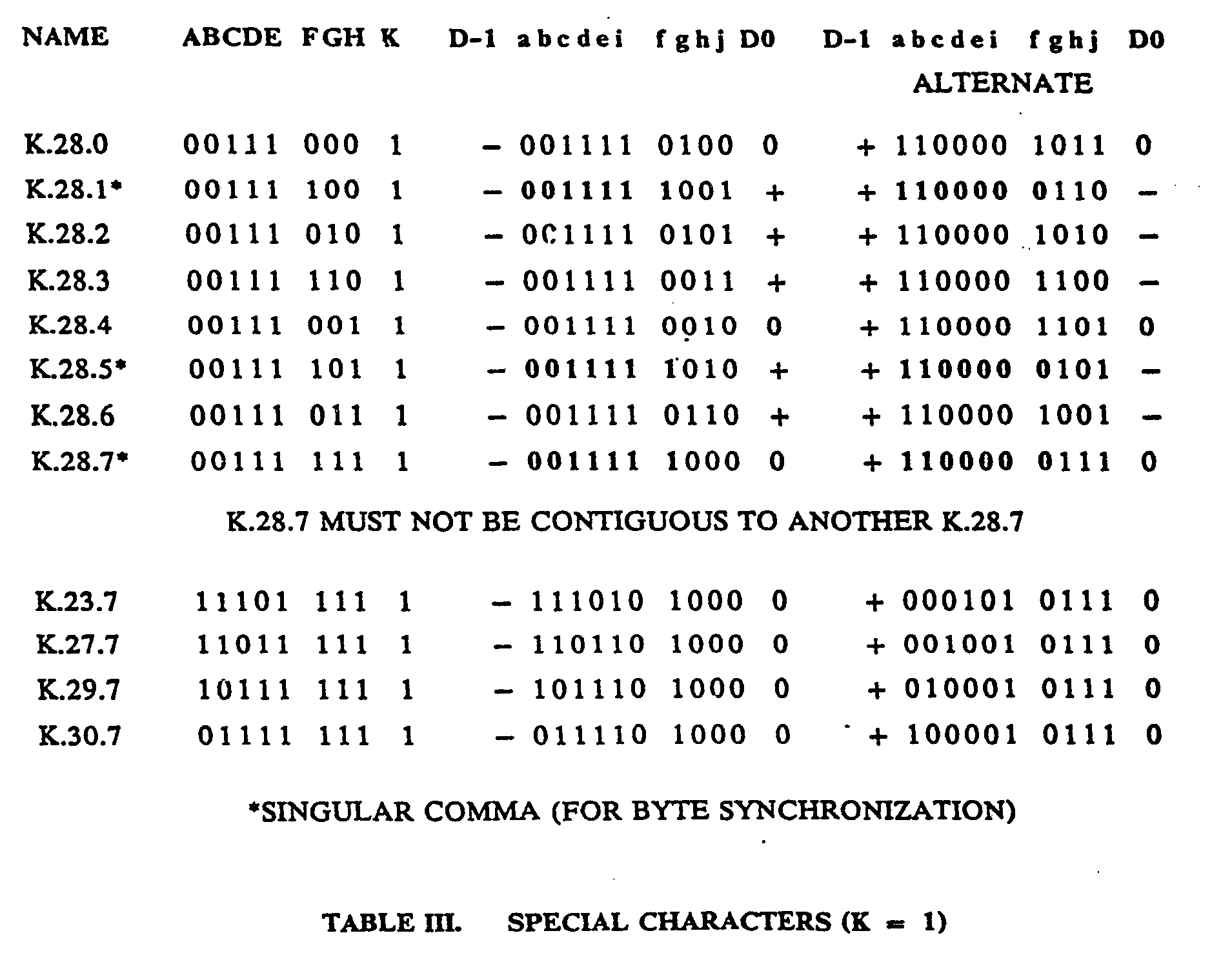

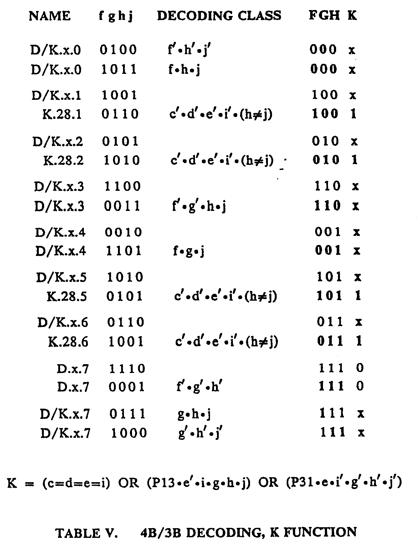
Claims (19)
Applications Claiming Priority (2)
| Application Number | Priority Date | Filing Date | Title |
|---|---|---|---|
| US06/394,045 US4486739A (en) | 1982-06-30 | 1982-06-30 | Byte oriented DC balanced (0,4) 8B/10B partitioned block transmission code |
| US394045 | 1989-08-15 |
Publications (3)
| Publication Number | Publication Date |
|---|---|
| EP0097763A2 true EP0097763A2 (en) | 1984-01-11 |
| EP0097763A3 EP0097763A3 (en) | 1987-01-14 |
| EP0097763B1 EP0097763B1 (en) | 1988-09-21 |
Family
ID=23557333
Family Applications (1)
| Application Number | Title | Priority Date | Filing Date |
|---|---|---|---|
| EP83101758A Expired EP0097763B1 (en) | 1982-06-30 | 1983-02-23 | A method and apparatus for producing a dc balanced (0,4) run length limited rate 8b/10b code from an input data stream |
Country Status (5)
| Country | Link |
|---|---|
| US (1) | US4486739A (en) |
| EP (1) | EP0097763B1 (en) |
| JP (1) | JPS5910056A (en) |
| CA (1) | CA1190324A (en) |
| DE (1) | DE3378098D1 (en) |
Cited By (28)
| Publication number | Priority date | Publication date | Assignee | Title |
|---|---|---|---|---|
| EP0123563A2 (en) * | 1983-04-26 | 1984-10-31 | Sony Corporation | Converting digital signals |
| EP0147677A2 (en) * | 1983-12-30 | 1985-07-10 | International Business Machines Corporation | Method of coding to minimize delay at a communication node |
| EP0150083A2 (en) * | 1984-01-20 | 1985-07-31 | Koninklijke Philips Electronics N.V. | Apparatus for encoding n-bit information words into m-bit code words, apparatus for decoding m-bit code words into n-bit information words |
| EP0150082A2 (en) * | 1984-01-20 | 1985-07-31 | Koninklijke Philips Electronics N.V. | Method of transmitting information, encoding device for use in the method, and decoding device for use in the method |
| EP0162558A2 (en) * | 1984-05-21 | 1985-11-27 | Matsushita Electric Industrial Co., Ltd. | Method and apparatus for generating a run length limited code |
| US4617552A (en) * | 1983-08-29 | 1986-10-14 | Sony Corporation | Method and apparatus for converting a digital data |
| EP0275585A1 (en) * | 1986-12-12 | 1988-07-27 | Optical Storage International Holland | Method of transmitting n-bit information words, information transmission system for carrying out the method, and encoding device and decoding device for use in the information-transmission system |
| EP0375645A2 (en) * | 1988-12-19 | 1990-06-27 | International Business Machines Corporation | Serial link transparent mode disparity control |
| EP0414368A2 (en) * | 1989-07-17 | 1991-02-27 | Digital Equipment Corporation | Method and apparatus for data and forward error correction coding for low DC-offset and short run length |
| EP0464910A2 (en) * | 1990-06-30 | 1992-01-08 | Philips Patentverwaltung GmbH | Transmission device with a block-coded main channel and an additional channel |
| EP0471130A1 (en) * | 1990-08-16 | 1992-02-19 | International Business Machines Corporation | Coding method and apparatus for pipelined and parallel processing |
| AU620995B2 (en) * | 1989-05-31 | 1992-02-27 | International Computers Limited | Data transmission code |
| EP0537407A1 (en) * | 1991-10-14 | 1993-04-21 | International Business Machines Corporation | Flexible encoding method and architecture for high-speed data transmission and storage |
| EP0556983A1 (en) * | 1992-02-21 | 1993-08-25 | Advanced Micro Devices, Inc. | 8B/10B encoder |
| EP0556981A1 (en) * | 1992-02-21 | 1993-08-25 | Advanced Micro Devices, Inc. | Method and apparatus for transmitting and receiving code |
| EP0604927A2 (en) * | 1992-12-30 | 1994-07-06 | Datatape Incorporated | A simple coding scheme for DC free channel codes of form M/N, where M=N-1 and M and N are positive integers |
| US5396239A (en) * | 1989-07-17 | 1995-03-07 | Digital Equipment Corporation | Data and forward error control coding techniques for digital signals |
| EP0717537A1 (en) * | 1994-12-13 | 1996-06-19 | International Business Machines Corporation | Line coding for ATM |
| EP0725486A2 (en) * | 1995-02-01 | 1996-08-07 | International Business Machines Corporation | Transmission code having local parity |
| WO1997006624A1 (en) * | 1995-08-03 | 1997-02-20 | Seagate Technology, Inc. | Matched spectral null encoder/decoder |
| EP1058432A2 (en) * | 1999-06-01 | 2000-12-06 | Lucent Technologies Inc. | A low disparity coding method for digital data |
| GB2355165A (en) * | 1999-07-12 | 2001-04-11 | Ibm | Maximum transition run (MTR) encoding where prohibited portions of block coded data are replaced with substitute portions |
| EP1573992A2 (en) * | 2002-12-10 | 2005-09-14 | Rambus, Inc. | Technique for improving the quality of digital signals in a multi-level signaling system |
| EP2725716A1 (en) * | 2012-10-26 | 2014-04-30 | Altera Corporation | Apparatus for improved encoding and associated methods |
| EP2892156A3 (en) * | 2013-12-27 | 2015-10-28 | Altera Corporation | Apparatus for improved encoding and associated methods |
| NL2019153A (en) | 2016-06-30 | 2018-01-09 | Mapper Lithography Ip Bv | Device and method for generating a decoded and synchronized output |
| NL2019144A (en) | 2016-06-29 | 2018-01-09 | Mapper Lithography Ip Bv | Encoding device and method for encoding a sequence of m-bit pattern words and outputting a frame comprising corresponding n-bit symbols |
| US9942063B2 (en) | 2012-10-26 | 2018-04-10 | Altera Corporation | Apparatus for improved encoding and associated methods |
Families Citing this family (395)
| Publication number | Priority date | Publication date | Assignee | Title |
|---|---|---|---|---|
| US4833470A (en) * | 1986-07-15 | 1989-05-23 | Matsushita Electric Industrial Co., Ltd. | Code conversion apparatus |
| FR2606239A1 (en) * | 1986-10-30 | 1988-05-06 | Bull Sa | METHOD AND DEVICE FOR TRANSMITTING DIGITAL DATA |
| US4881076A (en) * | 1987-12-01 | 1989-11-14 | International Business Machines Corporation | Encoding for pit-per-transition optical data recording |
| US4939735A (en) * | 1988-07-21 | 1990-07-03 | International Business Machines Corporation | Information handling system having serial channel to control unit link |
| US4975916A (en) * | 1988-07-26 | 1990-12-04 | International Business Machines Corporation | Character snychronization |
| US5333271A (en) * | 1989-04-28 | 1994-07-26 | International Business Machines Corporation | Methods and apparatus for performing data chaining in data streaming mode through a channel extender |
| GB8915137D0 (en) * | 1989-06-30 | 1989-08-23 | Inmos Ltd | Message routing |
| US5229769A (en) * | 1992-02-21 | 1993-07-20 | Advanced Micro Devices, Inc. | Method and circuit for performing running disparity measurements |
| US5048062A (en) * | 1989-10-30 | 1991-09-10 | International Business Machines Corp. | Transmitting commands over a serial link |
| CA2044051A1 (en) * | 1990-06-29 | 1991-12-30 | Paul C. Wade | System and method for error detection and reducing simultaneous switching noise |
| US5392168A (en) * | 1990-08-31 | 1995-02-21 | Matsushita Electric Industrial Co., Ltd. | Method of recording digital video and audio data |
| US5390041A (en) * | 1991-11-06 | 1995-02-14 | Cray Research, Inc. | Fiber optic channel extender interface method and apparatus |
| US5625644A (en) * | 1991-12-20 | 1997-04-29 | Myers; David J. | DC balanced 4B/8B binary block code for digital data communications |
| US5548623A (en) * | 1992-02-20 | 1996-08-20 | International Business Machines Corporation | Null words for pacing serial links to driver and receiver speeds |
| US5301196A (en) * | 1992-03-16 | 1994-04-05 | International Business Machines Corporation | Half-speed clock recovery and demultiplexer circuit |
| US5648776A (en) * | 1993-04-30 | 1997-07-15 | International Business Machines Corporation | Serial-to-parallel converter using alternating latches and interleaving techniques |
| GB9312071D0 (en) * | 1993-06-11 | 1993-07-28 | Inmos Ltd | Encoding scheme |
| GB9312136D0 (en) * | 1993-06-11 | 1993-07-28 | Inmos Ltd | Transmission of messages |
| EP0629067B1 (en) * | 1993-06-11 | 2003-01-22 | STMicroelectronics Limited | 4B6B Coding |
| GB9312135D0 (en) * | 1993-06-11 | 1993-07-28 | Inmos Ltd | Generation of checking data |
| US5517519A (en) * | 1993-06-14 | 1996-05-14 | International Business Machines Corporation | Apparatus for repowering and monitoring serial links |
| US5832310A (en) * | 1993-12-30 | 1998-11-03 | Unisys Corporation | Serial I/O channel having dependent and synchronous sources of control data and user defined data |
| US5463762A (en) * | 1993-12-30 | 1995-10-31 | Unisys Corporation | I/O subsystem with header and error detection code generation and checking |
| US5553302A (en) * | 1993-12-30 | 1996-09-03 | Unisys Corporation | Serial I/O channel having independent and asynchronous facilities with sequence recognition, frame recognition, and frame receiving mechanism for receiving control and user defined data |
| US5598442A (en) * | 1994-06-17 | 1997-01-28 | International Business Machines Corporation | Self-timed parallel inter-system data communication channel |
| US5784387A (en) * | 1994-10-31 | 1998-07-21 | International Business Machines Corporation | Method for detecting start-of-frame, end of frame and idle words in a data stream |
| JP2944440B2 (en) * | 1994-12-27 | 1999-09-06 | 日本電気株式会社 | Time division multiplex transmission equipment |
| US6111528A (en) * | 1995-06-07 | 2000-08-29 | Emc Corporation | Communications arrangements for network digital data processing system |
| US5635933A (en) * | 1995-06-30 | 1997-06-03 | Quantum Corporation | Rate 16/17 (d=0,G=6/I=7) modulation code for a magnetic recording channel |
| US5999571A (en) * | 1995-10-05 | 1999-12-07 | Silicon Image, Inc. | Transition-controlled digital encoding and signal transmission system |
| US5825824A (en) * | 1995-10-05 | 1998-10-20 | Silicon Image, Inc. | DC-balanced and transition-controlled encoding method and apparatus |
| US5974464A (en) * | 1995-10-06 | 1999-10-26 | Silicon Image, Inc. | System for high speed serial video signal transmission using DC-balanced coding |
| US5956370A (en) * | 1996-01-17 | 1999-09-21 | Lsi Logic Corporation | Wrap-back test system and method |
| US5787114A (en) * | 1996-01-17 | 1998-07-28 | Lsi Logic Corporation | Loop-back test system and method |
| US5781544A (en) * | 1996-01-17 | 1998-07-14 | Lsi Logic Corporation | Method for interleaving network traffic over serial lines |
| US5790563A (en) * | 1996-02-05 | 1998-08-04 | Lsi Logic Corp. | Self test of core with unpredictable latency |
| US5781038A (en) * | 1996-02-05 | 1998-07-14 | Lsi Logic Corporation | High speed phase locked loop test method and means |
| US5896426A (en) * | 1996-02-05 | 1999-04-20 | Lsi Logic Corporation | Programmable synchronization character |
| DE69733864T2 (en) * | 1996-03-11 | 2006-08-03 | Hewlett-Packard Development Co., L.P., Houston | DEVICE AND METHOD FOR DATA TRANSMISSION OF DATA WORD BLOCKS TOGETHER WITH CONTROL WORDS |
| US5663724A (en) * | 1996-03-28 | 1997-09-02 | Seagate Technology, Inc. | 16B/20B encoder |
| US5802080A (en) * | 1996-03-28 | 1998-09-01 | Seagate Technology, Inc. | CRC checking using a CRC generator in a multi-port design |
| US6016330A (en) * | 1996-10-18 | 2000-01-18 | International Business Machines Corporation | Encoding and detection of balanced codes |
| US6027195A (en) | 1996-11-12 | 2000-02-22 | Varis Corporation | System and method for synchronizing the piezoelectric clock sources of a plurality of ink jet printheads |
| US6278744B1 (en) * | 1996-11-15 | 2001-08-21 | Conexant Systems, Inc. | System for controlling and shaping the spectrum and redundancy of signal-point limited transmission |
| US6192087B1 (en) * | 1996-11-15 | 2001-02-20 | Conexant Systems, Inc. | Method and apparatus for spectral shaping in signal-point limited transmission systems |
| US5970100A (en) * | 1996-11-15 | 1999-10-19 | Conexant Systems, Inc. | System for controlling and shaping the spectrum and redundancy of signal-point limited transmission |
| WO1998023060A1 (en) * | 1996-11-22 | 1998-05-28 | Sony Corporation | Method and device for transmitting data |
| KR100198448B1 (en) * | 1996-12-20 | 1999-06-15 | 이계철 | Nb2p encoder and nb2p decoder |
| WO1998034413A2 (en) | 1997-01-30 | 1998-08-06 | Fujitsu Network Communications, Inc. | Data encoder/decoder for a high speed serial link |
| GB2324214A (en) | 1997-04-08 | 1998-10-14 | Power X Limited | Synchronising arrangements |
| US6459331B1 (en) * | 1997-09-02 | 2002-10-01 | Kabushiki Kaisha Toshiba | Noise suppression circuit, ASIC, navigation apparatus communication circuit, and communication apparatus having the same |
| US6279057B1 (en) | 1997-11-17 | 2001-08-21 | Seagate Technology, Inc. | Communications system having dedicated frame buffers located in a channel node connected to two ports of the channel node for receiving frames |
| JP2003534670A (en) | 1997-12-11 | 2003-11-18 | テレフオンアクチーボラゲツト エル エム エリクソン(パブル) | Redundant termination for dynamic fault isolation |
| US6167077A (en) * | 1997-12-23 | 2000-12-26 | Lsi Logic Corporation | Using multiple high speed serial lines to transmit high data rates while compensating for overall skew |
| CN1309849A (en) * | 1998-02-24 | 2001-08-22 | 西加特技术有限责任公司 | Preserving loop fairness with dynamic half-duplex |
| US6330591B1 (en) | 1998-03-09 | 2001-12-11 | Lsi Logic Corporation | High speed serial line transceivers integrated into a cache controller to support coherent memory transactions in a loosely coupled network |
| US6898201B1 (en) * | 1998-03-17 | 2005-05-24 | Apple Computer, Inc. | Apparatus and method for inter-node communication |
| US6396819B1 (en) | 1998-03-21 | 2002-05-28 | Richard D. Fleeter | Low-cost satellite communication system |
| US6046691A (en) * | 1998-04-13 | 2000-04-04 | Lucent Technologies Inc. | Rate 16/17 (0,5) modulation code apparatus and method for partial response magnetic recording channels |
| US6351501B1 (en) | 1998-06-29 | 2002-02-26 | National Semiconductro Corporation | Apparatus and method for providing direct current balanced code |
| US6295010B1 (en) | 1998-07-02 | 2001-09-25 | Seagate Technology, Llc | 8B/10B encoder system and method |
| KR100281738B1 (en) | 1998-07-13 | 2001-02-15 | 이계철 | Encoding and decoding method of nibble inversion and block inversion code, code and decoder |
| US6496540B1 (en) * | 1998-07-22 | 2002-12-17 | International Business Machines Corporation | Transformation of parallel interface into coded format with preservation of baud-rate |
| AUPP702498A0 (en) * | 1998-11-09 | 1998-12-03 | Silverbrook Research Pty Ltd | Image creation method and apparatus (ART77) |
| US6279097B1 (en) | 1998-11-20 | 2001-08-21 | Allied Telesyn International Corporation | Method and apparatus for adaptive address lookup table generator for networking application |
| US6584101B2 (en) | 1998-12-04 | 2003-06-24 | Pmc-Sierra Ltd. | Communication method for packet switching systems |
| JP4026255B2 (en) * | 1998-12-18 | 2007-12-26 | ソニー株式会社 | Data transmission method and apparatus |
| US6225924B1 (en) * | 1998-12-22 | 2001-05-01 | International Business Machines Corporation | Transmission coding method and device |
| US7295554B1 (en) * | 1999-03-12 | 2007-11-13 | Lucent Technologies Inc. | Word Multiplexing of encoded signals into a higher bit rate serial data stream |
| US6204781B1 (en) | 1999-03-18 | 2001-03-20 | Lucent Technologies Inc. | General rate N/(N+1) (0, G) code construction for data coding |
| US6556628B1 (en) * | 1999-04-29 | 2003-04-29 | The University Of North Carolina At Chapel Hill | Methods and systems for transmitting and receiving differential signals over a plurality of conductors |
| US6618395B1 (en) * | 1999-05-27 | 2003-09-09 | 3Com Corporation | Physical coding sub-layer for transmission of data over multi-channel media |
| US6198413B1 (en) | 1999-07-01 | 2001-03-06 | International Business Machines Corporation | Partitioned DC balanced (0,6) 16B/18B transmission code with error correction |
| US6323789B1 (en) | 1999-08-16 | 2001-11-27 | Georgia Tech Research Corporation | Method and apparatus for combining a plurality of 8B/10B encoded data streams |
| KR100336496B1 (en) | 1999-08-20 | 2002-05-15 | 오길록 | Method and apparatus for encoding MB810 line code with the characteristics of minimum bandwidth and DC-free |
| US6718139B1 (en) * | 1999-09-13 | 2004-04-06 | Ciena Corporation | Optical fiber ring communication system |
| US6388590B1 (en) | 1999-09-24 | 2002-05-14 | Oak Technology, Inc. | Apparatus and method for transmitting data serially for use with an advanced technology attachment packet interface (atapi) |
| US6498663B1 (en) * | 1999-09-24 | 2002-12-24 | Scientific-Atlanta, Inc. | Methods and systems for detecting optical link performance of an optical link in a hybrid fiber coaxial path |
| US6388591B1 (en) | 1999-09-24 | 2002-05-14 | Oak Technology, Inc. | Apparatus and method for receiving data serially for use with an advanced technology attachment packet interface (atapi) |
| US7292608B1 (en) | 1999-11-30 | 2007-11-06 | Cisco Technology, Inc. | Method and apparatus for transferring synchronous optical network/synchronous digital hierarchy(SONET/SDH) frames on parallel transmission links |
| US6438728B1 (en) | 1999-12-15 | 2002-08-20 | Intel Corporation | Error character generation |
| US6606328B1 (en) | 1999-12-15 | 2003-08-12 | Intel Corporation | Look ahead encoder/decoder architecture |
| KR100315424B1 (en) * | 1999-12-24 | 2001-11-28 | 오길록 | 8B/10B encoder for high speed data transmit |
| US6829315B1 (en) | 2000-01-19 | 2004-12-07 | Mindspeed Technologies, Inc. | Alignment of parallel data channels using header detection signaling |
| US6738935B1 (en) | 2000-02-07 | 2004-05-18 | 3Com Corporation | Coding sublayer for multi-channel media with error correction |
| US7227884B2 (en) | 2000-02-28 | 2007-06-05 | Aeroastro, Inc. | Spread-spectrum receiver with progressive fourier transform |
| US6851086B2 (en) | 2000-03-31 | 2005-02-01 | Ted Szymanski | Transmitter, receiver, and coding scheme to increase data rate and decrease bit error rate of an optical data link |
| US7496100B2 (en) | 2000-04-18 | 2009-02-24 | Nippon Telegraph & Telephone Corporation | Method and apparatus for synchronous frame communication |
| JP3639184B2 (en) * | 2000-04-18 | 2005-04-20 | 日本電信電話株式会社 | Method for encoding control information in communication system |
| CA2307895A1 (en) | 2000-05-05 | 2001-11-05 | Pmc-Sierra Inc. | Bus interface for transfer of sonet/sdh data |
| US6392570B1 (en) | 2000-05-08 | 2002-05-21 | Crossroads Systems, Inc. | Method and system for decoding 8-bit/10-bit data using limited width decoders |
| US6662332B1 (en) | 2000-07-05 | 2003-12-09 | 3Com Corporation | Interleaver for burst error correction |
| US6581114B1 (en) | 2000-07-14 | 2003-06-17 | Texas Instruments Incorporated | Method and system for synchronizing serial data |
| US6687779B1 (en) | 2000-07-14 | 2004-02-03 | Texas Instruments Incorporated | Method and apparatus for transmitting control information across a serialized bus interface |
| US6763477B1 (en) | 2000-07-31 | 2004-07-13 | Hewlett-Packard Development Company, L.P. | Method and apparatus for transmitting and receiving data using a self clocking link protocol |
| JP2002046992A (en) * | 2000-08-04 | 2002-02-12 | Tcm Corp | Forklift with traverse system |
| US6760367B1 (en) * | 2000-09-26 | 2004-07-06 | Eni Technology, Inc. | Internal noise immune data communications scheme |
| TWI225341B (en) * | 2000-10-04 | 2004-12-11 | Ind Tech Res Inst | Distance-enhancing encoding method |
| KR100384886B1 (en) * | 2000-10-10 | 2003-05-22 | 주식회사 케이티 | Apparatus and Method for Using Nibble Inversion Code |
| FR2817683B1 (en) * | 2000-12-05 | 2003-01-31 | Bull Sa | METHOD FOR CODING / DECODING DIGITAL DATA TRANSMITTED ON A SERIAL LINK, ESPECIALLY OF THE TYPE SAID "8B / 10B", AND IMPLEMENTING DEVICE |
| US6691275B1 (en) * | 2000-12-14 | 2004-02-10 | Lsi Logic Corporation | Encoder with vector-calculated disparity logic |
| US6722968B2 (en) * | 2000-12-28 | 2004-04-20 | Orion International | Conversion attachment for bench grinder tool rest |
| US20040199522A1 (en) * | 2001-01-25 | 2004-10-07 | Hanna Edpalm | Method and apparatus for optimised indexing records of static data with different lengths |
| CA2337642A1 (en) * | 2001-02-21 | 2002-08-21 | Pmc-Sierra Inc. | A bus interface for transfer of multiple sonet/sdh rates over a serial backplane |
| US6650140B2 (en) * | 2001-03-19 | 2003-11-18 | Altera Corporation | Programmable logic device with high speed serial interface circuitry |
| US6501396B1 (en) * | 2001-03-30 | 2002-12-31 | Xilinx, Inc. | Scalable physical coding sublayer (PCS) and 8B/10B encoder |
| US6748567B1 (en) | 2001-05-01 | 2004-06-08 | Zettacom, Inc. | Method and system for error correction over serial link |
| AU2002305315A1 (en) * | 2001-05-08 | 2002-11-18 | International Business Machines Corporation | 8b/10b encoding and decoding for high speed applications |
| US6721086B2 (en) * | 2001-05-10 | 2004-04-13 | International Business Machines Corporation | Optical fiber emulator |
| US7127653B1 (en) * | 2001-07-05 | 2006-10-24 | Pmc-Sierra, Inc. | Apparatus and method for efficient data transport using transparent framing procedure |
| US6909385B2 (en) * | 2001-07-09 | 2005-06-21 | Seagate Technology Llc | Method and apparatus for suppressing low frequency content in digital data |
| KR100408416B1 (en) * | 2001-09-06 | 2003-12-06 | 삼성전자주식회사 | System and method for digital video signal transmission |
| US7046696B2 (en) * | 2001-09-21 | 2006-05-16 | International Business Machines Corporation | Multiplexing high priority, low bandwidth information on a traditional link protocol |
| US7065101B2 (en) * | 2001-11-15 | 2006-06-20 | International Business Machines Corporation | Modification of bus protocol packet for serial data synchronization |
| US7706524B2 (en) * | 2001-11-16 | 2010-04-27 | Rambus Inc. | Signal line routing to reduce crosstalk effects |
| US7142612B2 (en) * | 2001-11-16 | 2006-11-28 | Rambus, Inc. | Method and apparatus for multi-level signaling |
| US7181485B1 (en) | 2001-11-26 | 2007-02-20 | Integrated Device Technology, Inc. | Variably delayable transmission of packets between independently clocked source, intermediate, and destination circuits while maintaining orderly and timely processing in one or both of the intermediate and destination circuits |
| US6624770B1 (en) | 2001-12-13 | 2003-09-23 | Cisco Technology, Inc. | Block coding system and method of data aggregation |
| US6993393B2 (en) | 2001-12-19 | 2006-01-31 | Cardiac Pacemakers, Inc. | Telemetry duty cycle management system for an implantable medical device |
| US7729776B2 (en) | 2001-12-19 | 2010-06-01 | Cardiac Pacemakers, Inc. | Implantable medical device with two or more telemetry systems |
| ITMI20012795A1 (en) * | 2001-12-24 | 2003-06-24 | St Microelectronics Srl | BINARY CODING CIRCUIT |
| WO2003065670A1 (en) * | 2002-02-01 | 2003-08-07 | Igor Anatolievich Abrosimov | Means and method of data encoding and communication at rates above the channel bandwidth |
| US6985773B2 (en) | 2002-02-07 | 2006-01-10 | Cardiac Pacemakers, Inc. | Methods and apparatuses for implantable medical device telemetry power management |
| US20030152154A1 (en) * | 2002-02-14 | 2003-08-14 | Johnson Ryan C. | Coding and decoding system and method for high-speed data transmission |
| US7173943B1 (en) * | 2002-02-26 | 2007-02-06 | Computer Access Technology Corporation | Protocol analyzer and time precise method for capturing multi-directional packet traffic |
| US6768429B2 (en) * | 2002-02-28 | 2004-07-27 | Teknovus, Inc. | Multiplexing an additional bit stream with a primary bit stream with conversion between qB/rB and xB/yB encoded bit streams |
| US6775300B2 (en) | 2002-02-28 | 2004-08-10 | Teknovus, Inc. | Clock distribution in a communications network |
| US6624763B2 (en) * | 2002-02-28 | 2003-09-23 | Teknovus, Inc. | Multiplexing an additional bit stream with a primary bit stream |
| US7111220B1 (en) * | 2002-03-01 | 2006-09-19 | Xilinx, Inc. | Network physical layer with embedded multi-standard CRC generator |
| US6614369B1 (en) | 2002-03-05 | 2003-09-02 | International Business Machines Corporation | DC balanced 7B/8B, 9B/10B, and partitioned DC balanced 12B/14B, 17B/20B, and 16B/18B transmission codes |
| US7154299B2 (en) * | 2002-04-05 | 2006-12-26 | Stmicroelectronics Pvt. Ltd. | Architecture for programmable logic device |
| US6618281B1 (en) | 2002-05-15 | 2003-09-09 | International Business Machines Corporation | Content addressable memory (CAM) with error checking and correction (ECC) capability |
| US7020729B2 (en) * | 2002-05-16 | 2006-03-28 | Intel Corporation | Protocol independent data transmission interface |
| US6748328B2 (en) * | 2002-06-10 | 2004-06-08 | Halliburton Energy Services, Inc. | Determining fluid composition from fluid properties |
| US7082479B2 (en) * | 2002-06-19 | 2006-07-25 | Eastman Kodak Company | System and method for maintaining synchronized data transfer using a plurality of different control words individually indicative of the same single event |
| US7076724B2 (en) * | 2002-06-25 | 2006-07-11 | Lockheed Martin Corporation | System and method for forward error correction |
| US6794895B2 (en) | 2002-06-27 | 2004-09-21 | Intel Corporation | Power saving termination technique for differential signaling |
| US7339896B2 (en) * | 2002-09-10 | 2008-03-04 | International Business Machines Corporation | Available bandwidth detector for SAN switch ports |
| US7137056B2 (en) * | 2002-09-25 | 2006-11-14 | Infineon Technologies North America Corp. | Low error propagation rate 32/34 trellis code |
| US7038553B2 (en) | 2002-10-03 | 2006-05-02 | International Business Machines Corporation | Scalable computer system having surface-mounted capacitive couplers for intercommunication |
| KR100520302B1 (en) * | 2002-11-23 | 2005-10-13 | 한국전자통신연구원 | Apparatus and method for 8B/10B code-group validity check |
| US7103830B1 (en) | 2002-12-18 | 2006-09-05 | Applied Micro Circuits Corporation | DC balanced error correction coding |
| US6978416B2 (en) * | 2002-12-19 | 2005-12-20 | International Business Machines Corporation | Error correction with low latency for bus structures |
| US6940302B1 (en) | 2003-01-07 | 2005-09-06 | Altera Corporation | Integrated circuit output driver circuitry with programmable preemphasis |
| US7307446B1 (en) | 2003-01-07 | 2007-12-11 | Altera Corporation | Integrated circuit output driver circuitry with programmable preemphasis |
| US6831480B1 (en) | 2003-01-07 | 2004-12-14 | Altera Corporation | Programmable logic device multispeed I/O circuitry |
| US7606157B2 (en) * | 2003-01-23 | 2009-10-20 | Broadcom Corporation | Apparatus and method for communicating arbitrarily encoded data over a 1-gigabit ethernet |
| US7007120B2 (en) * | 2003-04-25 | 2006-02-28 | Hewlett-Packard Development Company, L.P. | Information transfer protocol having sync fields of different lengths |
| US7567592B2 (en) | 2003-05-01 | 2009-07-28 | Genesis Microchip Inc. | Packet based video display interface enumeration method |
| US8059673B2 (en) | 2003-05-01 | 2011-11-15 | Genesis Microchip Inc. | Dynamic resource re-allocation in a packet based video display interface |
| US8068485B2 (en) | 2003-05-01 | 2011-11-29 | Genesis Microchip Inc. | Multimedia interface |
| US8204076B2 (en) | 2003-05-01 | 2012-06-19 | Genesis Microchip Inc. | Compact packet based multimedia interface |
| KR100525726B1 (en) * | 2003-05-22 | 2005-11-02 | 전자부품연구원 | High speed 8bit/10bit encoder/decoder by reduction of logic group |
| US6747580B1 (en) | 2003-06-12 | 2004-06-08 | Silicon Image, Inc. | Method and apparatus for encoding or decoding data in accordance with an NB/(N+1)B block code, and method for determining such a block code |
| US7187307B1 (en) | 2003-06-12 | 2007-03-06 | Silicon Image, Inc. | Method and system for encapsulation of multiple levels of communication protocol functionality within line codes |
| US8576820B2 (en) * | 2003-07-03 | 2013-11-05 | Broadcom Corporation | Standby mode for use in a device having a multiple channel physical layer |
| JP2005033451A (en) * | 2003-07-11 | 2005-02-03 | Pioneer Electronic Corp | Video signal transmission system and method, transmitter and receiver |
| KR100523488B1 (en) * | 2003-07-15 | 2005-10-24 | 한국전자통신연구원 | MB810 encoder/decoder, dual mode encoder/decoder, and MB810 code generating method |
| US7272677B1 (en) | 2003-08-08 | 2007-09-18 | Altera Corporation | Multi-channel synchronization for programmable logic device serial interface |
| KR100538105B1 (en) * | 2003-08-18 | 2005-12-21 | 삼성전자주식회사 | Method for generating similar 8 bit/10bit code and apparatus using the same |
| US8251471B2 (en) | 2003-08-18 | 2012-08-28 | Fujifilm Dimatix, Inc. | Individual jet voltage trimming circuitry |
| US6888480B1 (en) * | 2003-08-28 | 2005-05-03 | Altera Corporation | Run-length violation detection circuitry and methods for using the same |
| JP2005079984A (en) * | 2003-09-01 | 2005-03-24 | Pioneer Electronic Corp | Method for transmitting video signal |
| US6812870B1 (en) | 2003-09-11 | 2004-11-02 | Xilinx, Inc. | Enhanced 8b/10b encoding/decoding and applications thereof |
| US20050058150A1 (en) * | 2003-09-16 | 2005-03-17 | Boles Glenn M. | Method and apparatus for enhancing packet communication |
| US7138930B1 (en) | 2003-09-17 | 2006-11-21 | Cypress Semiconductor Corporation | Multiple byte data path encoding/decoding device and method |
| US6911921B2 (en) * | 2003-09-19 | 2005-06-28 | International Business Machines Corporation | 5B/6B-T, 3B/4B-T and partitioned 8B/10B-T and 10B/12B transmission codes, and their implementation for high operating rates |
| US7131024B1 (en) | 2003-09-24 | 2006-10-31 | Altera Corporation | Multiple transmit data rates in programmable logic device serial interface |
| US6888376B1 (en) | 2003-09-24 | 2005-05-03 | Altera Corporation | Multiple data rates in programmable logic device serial interface |
| US7006016B1 (en) | 2003-10-10 | 2006-02-28 | Marvell International Ltd. | DC-free line codes |
| EP1676276A2 (en) * | 2003-10-13 | 2006-07-05 | Koninklijke Philips Electronics N.V. | Balanced disparity frame sync |
| US7443922B1 (en) | 2003-11-14 | 2008-10-28 | Altera Corporation | Circuitry for padded communication protocols |
| JP2005149140A (en) * | 2003-11-14 | 2005-06-09 | Wacom Co Ltd | Position detector and position indicator |
| US7084789B2 (en) * | 2003-11-17 | 2006-08-01 | Seagate Technology Llc | DC-free code having limited error propagation and limited complexity |
| US7143312B1 (en) | 2003-12-17 | 2006-11-28 | Altera Corporation | Alignment of recovered clock with data signal |
| US7486752B1 (en) | 2003-12-17 | 2009-02-03 | Altera Corporation | Alignment of clock signal with data signal |
| US6970020B1 (en) | 2003-12-17 | 2005-11-29 | Altera Corporation | Half-rate linear quardrature phase detector for clock recovery |
| US8543717B2 (en) * | 2003-12-23 | 2013-09-24 | Eastman Kodak Company | Retaining channel synchronization through use of alternate control characters |
| JP2005190036A (en) * | 2003-12-25 | 2005-07-14 | Hitachi Ltd | Storage controller and control method for storage controller |
| TWI295431B (en) * | 2003-12-26 | 2008-04-01 | Mediatek Inc | Data transformation apparatus and method for transforming data block |
| US6876315B1 (en) * | 2004-03-12 | 2005-04-05 | International Business Machines Corporation | DC-balanced 6B/8B transmission code with local parity |
| WO2005099817A1 (en) | 2004-04-07 | 2005-10-27 | Cardiac Pacemakers, Inc. | Rf wake-up of implantable medical device |
| WO2005099816A1 (en) * | 2004-04-07 | 2005-10-27 | Cardiac Pacemakers, Inc. | System and method for rf transceiver duty cycling in an implantable medical device |
| US7123173B1 (en) | 2004-04-08 | 2006-10-17 | Cypress Semiconductor Corporation | Method and system for a feed-forward encoder |
| KR100630686B1 (en) * | 2004-06-24 | 2006-10-02 | 삼성전자주식회사 | Data coding method for reducing skew of transmission data, encoding device and decoding device using the method, and transceiver with the encoding device and the decoding device and transmission and reception method |
| US7002492B2 (en) * | 2004-07-07 | 2006-02-21 | Seagate Technology Llc | High rate running digital sum-restricted code |
| US7302631B2 (en) * | 2004-07-16 | 2007-11-27 | Rambus Inc. | Low overhead coding techniques |
| FR2873518B1 (en) * | 2004-07-22 | 2008-12-19 | Canon Kk | METHOD FOR ENCODING AND DECODING A SEQUENCE OF WORDS, SIGNAL, ENCODER, DECODER, COMPUTER PROGRAMS AND CORRESPONDING STORAGE MEANS |
| FR2873532B1 (en) * | 2004-07-22 | 2006-09-22 | Canon Kk | METHOD FOR ENCODING AND DECODING A SEQUENCE OF ELEMENTS, SIGNAL, ENCODER, DECODER, COMPUTER PROGRAMS AND CORRESPONDING STORAGE MEANS |
| US7224595B2 (en) * | 2004-07-30 | 2007-05-29 | International Business Machines Corporation | 276-Pin buffered memory module with enhanced fault tolerance |
| US7296129B2 (en) | 2004-07-30 | 2007-11-13 | International Business Machines Corporation | System, method and storage medium for providing a serialized memory interface with a bus repeater |
| US7539800B2 (en) | 2004-07-30 | 2009-05-26 | International Business Machines Corporation | System, method and storage medium for providing segment level sparing |
| US7389375B2 (en) * | 2004-07-30 | 2008-06-17 | International Business Machines Corporation | System, method and storage medium for a multi-mode memory buffer device |
| US7539541B2 (en) | 2004-08-09 | 2009-05-26 | Cardiac Pacemakers, Inc. | Automatic power control for a radio frequency transceiver of an implantable device |
| US7890180B2 (en) * | 2004-08-09 | 2011-02-15 | Cardiac Pacemakers, Inc. | Secure remote access for an implantable medical device |
| US7240133B1 (en) | 2004-10-12 | 2007-07-03 | Altera Corporation | Reduced-area architecture for padded-protocol interface |
| US6914545B1 (en) | 2004-10-13 | 2005-07-05 | Seiko Epson Corporation | Circuitry and methods for reducing run-length of encoded data |
| US7722147B2 (en) * | 2004-10-15 | 2010-05-25 | Fujifilm Dimatix, Inc. | Printing system architecture |
| US7911625B2 (en) | 2004-10-15 | 2011-03-22 | Fujifilm Dimatrix, Inc. | Printing system software architecture |
| US7907298B2 (en) | 2004-10-15 | 2011-03-15 | Fujifilm Dimatix, Inc. | Data pump for printing |
| US8068245B2 (en) | 2004-10-15 | 2011-11-29 | Fujifilm Dimatix, Inc. | Printing device communication protocol |
| US8085428B2 (en) | 2004-10-15 | 2011-12-27 | Fujifilm Dimatix, Inc. | Print systems and techniques |
| US7664015B2 (en) * | 2004-10-20 | 2010-02-16 | L-3 Communications Security & Detection Systems | Inspection system with data acquisition system interconnect protocol |
| US7151470B1 (en) | 2004-10-20 | 2006-12-19 | Altera Corporation | Data converter with multiple conversions for padded-protocol interface |
| US7064685B1 (en) | 2004-10-20 | 2006-06-20 | Altera Corporation | Data converter with reduced component count for padded-protocol interface |
| US7183797B2 (en) * | 2004-10-29 | 2007-02-27 | Altera Corporation | Next generation 8B10B architecture |
| US7305574B2 (en) | 2004-10-29 | 2007-12-04 | International Business Machines Corporation | System, method and storage medium for bus calibration in a memory subsystem |
| US7356737B2 (en) | 2004-10-29 | 2008-04-08 | International Business Machines Corporation | System, method and storage medium for testing a memory module |
| US7395476B2 (en) * | 2004-10-29 | 2008-07-01 | International Business Machines Corporation | System, method and storage medium for providing a high speed test interface to a memory subsystem |
| US7299313B2 (en) | 2004-10-29 | 2007-11-20 | International Business Machines Corporation | System, method and storage medium for a memory subsystem command interface |
| US7331010B2 (en) * | 2004-10-29 | 2008-02-12 | International Business Machines Corporation | System, method and storage medium for providing fault detection and correction in a memory subsystem |
| US7441060B2 (en) | 2004-10-29 | 2008-10-21 | International Business Machines Corporation | System, method and storage medium for providing a service interface to a memory system |
| US7277988B2 (en) | 2004-10-29 | 2007-10-02 | International Business Machines Corporation | System, method and storage medium for providing data caching and data compression in a memory subsystem |
| US7512762B2 (en) | 2004-10-29 | 2009-03-31 | International Business Machines Corporation | System, method and storage medium for a memory subsystem with positional read data latency |
| US8199342B2 (en) | 2004-10-29 | 2012-06-12 | Fujifilm Dimatix, Inc. | Tailoring image data packets to properties of print heads |
| US20060126751A1 (en) * | 2004-12-10 | 2006-06-15 | Anthony Bessios | Technique for disparity bounding coding in a multi-level signaling system |
| US7404133B2 (en) * | 2004-12-12 | 2008-07-22 | Hewlett-Packard Development Company, L.P. | Error detection and correction employing modulation symbols satisfying predetermined criteria |
| US7461192B2 (en) | 2004-12-15 | 2008-12-02 | Rambus Inc. | Interface for bridging out-of-band information and preventing false presence detection of terminating devices |
| US7307554B2 (en) * | 2004-12-20 | 2007-12-11 | Kawasaki Microelectronics, Inc. | Parallel data transmission method and parallel data transmission system |
| US7081838B2 (en) * | 2004-12-29 | 2006-07-25 | Enigma Semiconductor, Inc. | 16b/10s coding apparatus and method |
| US7064683B1 (en) | 2005-01-19 | 2006-06-20 | Seagate Technology Llc | Speed optimized encoder with running disparity constraint |
| US7061406B1 (en) * | 2005-01-21 | 2006-06-13 | Rambus, Inc. | Low power, DC-balanced serial link transmitter |
| US7199728B2 (en) * | 2005-01-21 | 2007-04-03 | Rambus, Inc. | Communication system with low power, DC-balanced serial link |
| US20060164909A1 (en) * | 2005-01-24 | 2006-07-27 | International Business Machines Corporation | System, method and storage medium for providing programmable delay chains for a memory system |
| FI117780B (en) * | 2005-03-15 | 2007-02-15 | Elektrobit Testing Oy | Method and Test Arrangement for Testing a Device Using 8B / 10B Encoding and 8B / 10B Encoder and Decoder |
| US7664553B2 (en) | 2005-04-27 | 2010-02-16 | Cardiac Pacemakers, Inc. | System and method for enabling communications with implantable medical devices |
| US7876900B1 (en) * | 2005-05-23 | 2011-01-25 | Force 10 Networks, Inc. | Hybrid scrambled transmission coding |
| US7292161B2 (en) * | 2005-05-31 | 2007-11-06 | International Business Machines Corporation | NB/MB coding apparatus and method using both disparity independent and disparity dependent encoded vectors |
| US7656321B2 (en) * | 2005-06-02 | 2010-02-02 | Rambus Inc. | Signaling system |
| US7787526B2 (en) * | 2005-07-12 | 2010-08-31 | Mcgee James Ridenour | Circuits and methods for a multi-differential embedded-clock channel |
| US7304498B2 (en) * | 2005-07-20 | 2007-12-04 | Altera Corporation | Clock circuitry for programmable logic devices |
| DE102005035207A1 (en) * | 2005-07-27 | 2007-02-01 | Siemens Ag | Method and device for data transmission between two relatively moving components |
| US7812659B1 (en) | 2005-08-03 | 2010-10-12 | Altera Corporation | Clock signal circuitry for multi-channel data signaling |
| US7598767B1 (en) | 2005-08-12 | 2009-10-06 | Altera Corporation | Multi-standard data communication interface circuitry for programmable logic devices |
| JP4675721B2 (en) * | 2005-08-31 | 2011-04-27 | 三菱電機株式会社 | Parallel precoder circuit |
| JP4597820B2 (en) * | 2005-09-05 | 2010-12-15 | 三菱電機株式会社 | Parallel precoder circuit |
| US7158057B1 (en) * | 2005-09-07 | 2007-01-02 | Seiko Epson Corporation | Circuitry and methods for high speed data encoding |
| US7487426B2 (en) * | 2005-10-17 | 2009-02-03 | Enigma Semiconductor, Inc. | 64b/66b coding apparatus and method |
| US7478259B2 (en) | 2005-10-31 | 2009-01-13 | International Business Machines Corporation | System, method and storage medium for deriving clocks in a memory system |
| US7259699B1 (en) | 2005-11-23 | 2007-08-21 | Altera Corporation | Circuitry for providing configurable running disparity enforcement in 8B/10B encoding and error detection |
| US7685392B2 (en) | 2005-11-28 | 2010-03-23 | International Business Machines Corporation | Providing indeterminate read data latency in a memory system |
| FR2895634B1 (en) * | 2005-12-26 | 2008-02-15 | Sagem Defense Securite | SYSTEM AND METHOD FOR HIGH DIGITAL RATE VIDEO TRANSMISSION ON BOARD A VEHICLE |
| US7592953B2 (en) | 2005-12-30 | 2009-09-22 | Comtech Mobile Datacom Corporation | Mobile satellite communications |
| EP1814234B1 (en) * | 2006-01-20 | 2011-01-12 | Silicon Image, Inc. | Concurrent code checker and hardware efficient high- speed I/O having built- in self- test and debug features |
| US7984369B2 (en) * | 2006-01-20 | 2011-07-19 | Silicon Image, Inc. | Concurrent code checker and hardware efficient high-speed I/O having built-in self-test and debug features |
| US7676725B1 (en) | 2006-02-27 | 2010-03-09 | The United States Of America As Represented By The Director, National Security Agency | Method of code generation that minimizes error propagation |
| KR100885869B1 (en) * | 2006-04-04 | 2009-02-27 | 삼성전자주식회사 | Method and Record readable medium, and apparatus for reducing noise by using Preamble Code in single ended parallel interface |
| US7636813B2 (en) | 2006-05-22 | 2009-12-22 | International Business Machines Corporation | Systems and methods for providing remote pre-fetch buffers |
| US7640386B2 (en) | 2006-05-24 | 2009-12-29 | International Business Machines Corporation | Systems and methods for providing memory modules with multiple hub devices |
| US7594055B2 (en) | 2006-05-24 | 2009-09-22 | International Business Machines Corporation | Systems and methods for providing distributed technology independent memory controllers |
| US7869343B1 (en) * | 2006-06-05 | 2011-01-11 | Altera Corporation | Field programmable gate array architectures and methods for supporting forward error correction |
| US7584336B2 (en) | 2006-06-08 | 2009-09-01 | International Business Machines Corporation | Systems and methods for providing data modification operations in memory subsystems |
| EP1868109A1 (en) * | 2006-06-12 | 2007-12-19 | Siemens Aktiengesellschaft | Event signalling between peripheral modules and a processing unit |
| US7792137B2 (en) * | 2006-07-05 | 2010-09-07 | Abidanet, Llc | Self-organized and self-managed ad hoc communications network |
| US7518534B2 (en) * | 2006-07-28 | 2009-04-14 | Cypress Semiconductor Corporation | 8-bit to 10-bit encoding method and apparatus |
| US7493439B2 (en) | 2006-08-01 | 2009-02-17 | International Business Machines Corporation | Systems and methods for providing performance monitoring in a memory system |
| US7669086B2 (en) | 2006-08-02 | 2010-02-23 | International Business Machines Corporation | Systems and methods for providing collision detection in a memory system |
| US7602318B1 (en) * | 2006-08-07 | 2009-10-13 | Integrated Device Technology, Inc. | Method and apparatus for improved efficiency in protocols using character coding |
| US7581073B2 (en) | 2006-08-09 | 2009-08-25 | International Business Machines Corporation | Systems and methods for providing distributed autonomous power management in a memory system |
| US7587559B2 (en) | 2006-08-10 | 2009-09-08 | International Business Machines Corporation | Systems and methods for memory module power management |
| US7490217B2 (en) | 2006-08-15 | 2009-02-10 | International Business Machines Corporation | Design structure for selecting memory busses according to physical memory organization information stored in virtual address translation tables |
| US7539842B2 (en) | 2006-08-15 | 2009-05-26 | International Business Machines Corporation | Computer memory system for selecting memory buses according to physical memory organization information stored in virtual address translation tables |
| JP4783245B2 (en) * | 2006-09-01 | 2011-09-28 | 株式会社日立製作所 | Transceiver, transmitter, and receiver |
| US7870459B2 (en) * | 2006-10-23 | 2011-01-11 | International Business Machines Corporation | High density high reliability memory module with power gating and a fault tolerant address and command bus |
| US7477522B2 (en) | 2006-10-23 | 2009-01-13 | International Business Machines Corporation | High density high reliability memory module with a fault tolerant address and command bus |
| US8201071B2 (en) * | 2006-11-15 | 2012-06-12 | Qimonda Ag | Information transmission and reception |
| US7953162B2 (en) * | 2006-11-17 | 2011-05-31 | Intersil Americas Inc. | Use of differential pair as single-ended data paths to transport low speed data |
| JP4902665B2 (en) * | 2006-11-17 | 2012-03-21 | アラクサラネットワークス株式会社 | Data transmission apparatus and transmission code generation method |
| US8275080B2 (en) | 2006-11-17 | 2012-09-25 | Comtech Mobile Datacom Corporation | Self-supporting simplex packets |
| US7721140B2 (en) | 2007-01-02 | 2010-05-18 | International Business Machines Corporation | Systems and methods for improving serviceability of a memory system |
| US7928884B2 (en) * | 2007-01-11 | 2011-04-19 | Siflare, Inc. | Analog-to-digital converter with a balanced output |
| US7603526B2 (en) | 2007-01-29 | 2009-10-13 | International Business Machines Corporation | Systems and methods for providing dynamic memory pre-fetch |
| US7606988B2 (en) * | 2007-01-29 | 2009-10-20 | International Business Machines Corporation | Systems and methods for providing a dynamic memory bank page policy |
| US7405679B1 (en) * | 2007-01-30 | 2008-07-29 | International Business Machines Corporation | Techniques for 9B10B and 7B8B coding and decoding |
| WO2008107828A1 (en) * | 2007-03-02 | 2008-09-12 | Nxp B.V. | Fast powering-up of data communication system |
| EP2127186A2 (en) | 2007-03-20 | 2009-12-02 | Nxp B.V. | Fast powering-up of data communication system |
| JP4927617B2 (en) * | 2007-03-30 | 2012-05-09 | 株式会社日立製作所 | Data transmission apparatus and transmission code generation method |
| US8175141B2 (en) * | 2007-08-20 | 2012-05-08 | Computer Access Technology Corporation | Method and apparatus for calibrating equalizers without knowledge of the data pattern being received |
| US8036128B2 (en) * | 2007-09-28 | 2011-10-11 | Alcatel Lucent | Method for communicating backpressure messages in a data communications system |
| US8284749B2 (en) | 2008-03-10 | 2012-10-09 | Comtech Mobile Datacom Corporation | Time slot synchronized, flexible bandwidth communication system |
| US8019895B2 (en) * | 2008-03-25 | 2011-09-13 | International Business Machines Corporation | Serial attached SCSI and serial ATA wide port tunnelling through a fibre channel connection |
| US7949789B2 (en) * | 2008-03-25 | 2011-05-24 | International Business Machines Corporation | Distance extender for serial attached SCSI and serial ATA |
| US7852242B2 (en) * | 2008-05-15 | 2010-12-14 | Taiwan Semiconductor Manufacturing Company, Ltd. | Increasing 8B/10B coding speed using a disparity look-ahead table |
| US8219846B2 (en) | 2008-05-20 | 2012-07-10 | Xilinx, Inc. | Circuit for and method of receiving video data |
| US8081705B2 (en) * | 2008-06-27 | 2011-12-20 | Crestron Electronics Inc. | Digital video physical layer using a multi-level data code |
| EP2148178B1 (en) | 2008-07-23 | 2012-04-18 | SICK STEGMANN GmbH | Digital, bidirectional data transfer method |
| JP5161176B2 (en) * | 2008-09-26 | 2013-03-13 | 太陽誘電株式会社 | Visible light communication transmitter and visible light communication system |
| WO2010039108A1 (en) | 2008-10-02 | 2010-04-08 | Zenko Technologies, Inc. | Data sampling circuit and method for clock and data recovery |
| US7777652B2 (en) * | 2008-10-29 | 2010-08-17 | Silicon Image, Inc. | Coding system for memory systems employing high-speed serial links |
| US20100115140A1 (en) * | 2008-10-30 | 2010-05-06 | Micron Technology, Inc. | Encoded addressing within control code for bus communication |
| PL216621B1 (en) | 2008-12-12 | 2014-04-30 | Pietrak Rafał Zakład Techniki Komputerowej | Method of coding and decoding of the synchronous serial transmission, preferably in the energy saving devices and in the optical fibre connections |
| US8347199B2 (en) * | 2009-01-21 | 2013-01-01 | Cisco Technology, Inc. | Enhanced error detection in multilink serdes channels |
| US8548107B1 (en) | 2009-01-26 | 2013-10-01 | Comtech Mobile Datacom Corporation | Advanced multi-user detector |
| US9106364B1 (en) | 2009-01-26 | 2015-08-11 | Comtech Mobile Datacom Corporation | Signal processing of a high capacity waveform |
| JP5485736B2 (en) * | 2009-02-10 | 2014-05-07 | パナソニック株式会社 | Transmitter |
| EP2246984B1 (en) * | 2009-04-28 | 2013-07-03 | VEGA Grieshaber KG | Diagnosis apparatus for monitoring an analogue-digital conversion apparatus |
| EP2293449B1 (en) * | 2009-05-21 | 2013-07-10 | Huawei Technologies Co., Ltd. | Method and apparatus for generating a coding table |
| KR101283844B1 (en) | 2009-06-19 | 2013-07-08 | 후지쯔 가부시끼가이샤 | Data transfer method, code conversion circuit, and device |
| WO2010146714A1 (en) * | 2009-06-19 | 2010-12-23 | 富士通株式会社 | Data transfer method, code conversion circuit, and device |
| US7961520B2 (en) * | 2009-08-18 | 2011-06-14 | Seagate Technology Llc | Encoding and decoding to reduce switching of flash memory transistors |
| US8675711B1 (en) | 2009-09-25 | 2014-03-18 | Comtech Mobile Datacom Corporation | System and methods for dynamic spread spectrum usage |
| JP2011103552A (en) * | 2009-11-10 | 2011-05-26 | Sony Corp | Information processor, and signal processing method |
| JP5583999B2 (en) | 2010-03-24 | 2014-09-03 | 太陽誘電株式会社 | Visible light communication transmitter and visible light communication system |
| US9288089B2 (en) | 2010-04-30 | 2016-03-15 | Ecole Polytechnique Federale De Lausanne (Epfl) | Orthogonal differential vector signaling |
| US8718184B1 (en) | 2012-05-03 | 2014-05-06 | Kandou Labs S.A. | Finite state encoders and decoders for vector signaling codes |
| US9985634B2 (en) | 2010-05-20 | 2018-05-29 | Kandou Labs, S.A. | Data-driven voltage regulator |
| US9288082B1 (en) | 2010-05-20 | 2016-03-15 | Kandou Labs, S.A. | Circuits for efficient detection of vector signaling codes for chip-to-chip communication using sums of differences |
| US8593305B1 (en) | 2011-07-05 | 2013-11-26 | Kandou Labs, S.A. | Efficient processing and detection of balanced codes |
| US9362962B2 (en) | 2010-05-20 | 2016-06-07 | Kandou Labs, S.A. | Methods and systems for energy-efficient communications interface |
| US9077386B1 (en) | 2010-05-20 | 2015-07-07 | Kandou Labs, S.A. | Methods and systems for selection of unions of vector signaling codes for power and pin efficient chip-to-chip communication |
| US9251873B1 (en) | 2010-05-20 | 2016-02-02 | Kandou Labs, S.A. | Methods and systems for pin-efficient memory controller interface using vector signaling codes for chip-to-chip communications |
| US9479369B1 (en) | 2010-05-20 | 2016-10-25 | Kandou Labs, S.A. | Vector signaling codes with high pin-efficiency for chip-to-chip communication and storage |
| US9083576B1 (en) | 2010-05-20 | 2015-07-14 | Kandou Labs, S.A. | Methods and systems for error detection and correction using vector signal prediction |
| US9300503B1 (en) | 2010-05-20 | 2016-03-29 | Kandou Labs, S.A. | Methods and systems for skew tolerance in and advanced detectors for vector signaling codes for chip-to-chip communication |
| US9450744B2 (en) | 2010-05-20 | 2016-09-20 | Kandou Lab, S.A. | Control loop management and vector signaling code communications links |
| US9106238B1 (en) | 2010-12-30 | 2015-08-11 | Kandou Labs, S.A. | Sorting decoder |
| US9564994B2 (en) | 2010-05-20 | 2017-02-07 | Kandou Labs, S.A. | Fault tolerant chip-to-chip communication with advanced voltage |
| US9246713B2 (en) | 2010-05-20 | 2016-01-26 | Kandou Labs, S.A. | Vector signaling with reduced receiver complexity |
| US9401828B2 (en) | 2010-05-20 | 2016-07-26 | Kandou Labs, S.A. | Methods and systems for low-power and pin-efficient communications with superposition signaling codes |
| US9106220B2 (en) | 2010-05-20 | 2015-08-11 | Kandou Labs, S.A. | Methods and systems for high bandwidth chip-to-chip communications interface |
| US9596109B2 (en) | 2010-05-20 | 2017-03-14 | Kandou Labs, S.A. | Methods and systems for high bandwidth communications interface |
| WO2011151469A1 (en) | 2010-06-04 | 2011-12-08 | Ecole Polytechnique Federale De Lausanne | Error control coding for orthogonal differential vector signaling |
| CN103141066B (en) * | 2010-10-12 | 2015-06-10 | 松下电器产业株式会社 | Transmission circuit, reception circuit, transmission method, reception method, communication system and communication method therefor |
| US9275720B2 (en) | 2010-12-30 | 2016-03-01 | Kandou Labs, S.A. | Differential vector storage for dynamic random access memory |
| US8572300B2 (en) * | 2011-10-26 | 2013-10-29 | Taiwan Semiconductor Manufacturing Co., Ltd. | Physical coding sublayer (PCS) architecture for synchronizing data between different reference clocks |
| IN2014CN03997A (en) | 2011-10-28 | 2015-09-04 | Koninkl Philips Nv | |
| JP5987319B2 (en) | 2012-01-06 | 2016-09-07 | 富士ゼロックス株式会社 | Transmission / reception system and program |
| JP5982869B2 (en) | 2012-02-28 | 2016-08-31 | 富士ゼロックス株式会社 | Transmission / reception system and program |
| JP5348263B2 (en) | 2012-02-29 | 2013-11-20 | 富士通株式会社 | Data transmission apparatus, data transmission system, and data transmission method |
| US9268683B1 (en) | 2012-05-14 | 2016-02-23 | Kandou Labs, S.A. | Storage method and apparatus for random access memory using codeword storage |
| KR101983274B1 (en) | 2012-05-18 | 2019-05-30 | 삼성전자주식회사 | PCRAM : Phase Change Random Access Memory device and Method for sensing threrof |
| EP2926260B1 (en) | 2013-01-17 | 2019-04-03 | Kandou Labs S.A. | Methods and systems for chip-to-chip communication with reduced simultaneous switching noise |
| WO2014172377A1 (en) | 2013-04-16 | 2014-10-23 | Kandou Labs, S.A. | Methods and systems for high bandwidth communications interface |
| US9687659B2 (en) | 2013-06-25 | 2017-06-27 | Biotronik Se & Co. Kg | Conductive intra-body communication for implantable medical devices |
| WO2014210074A1 (en) | 2013-06-25 | 2014-12-31 | Kandou Labs SA | Vector signaling with reduced receiver complexity |
| US9106465B2 (en) | 2013-11-22 | 2015-08-11 | Kandou Labs, S.A. | Multiwire linear equalizer for vector signaling code receiver |
| US9806761B1 (en) | 2014-01-31 | 2017-10-31 | Kandou Labs, S.A. | Methods and systems for reduction of nearest-neighbor crosstalk |
| EP3100424B1 (en) | 2014-02-02 | 2023-06-07 | Kandou Labs S.A. | Method and apparatus for low power chip-to-chip communications with constrained isi ratio |
| US9369312B1 (en) | 2014-02-02 | 2016-06-14 | Kandou Labs, S.A. | Low EMI signaling for parallel conductor interfaces |
| US9270415B2 (en) | 2014-02-03 | 2016-02-23 | Valens Semiconductor Ltd. | Encoding payloads according to data types while maintaining running disparity |
| US9401729B2 (en) | 2014-02-03 | 2016-07-26 | Valens Semiconductor Ltd. | Maintaining running disparity while utilizing different line-codes |
| US9407394B2 (en) | 2014-02-03 | 2016-08-02 | Valens Semiconductor Ltd. | Frequent flow control by replacing certain idle words with bitwise complement words |
| US9594719B2 (en) | 2014-02-03 | 2017-03-14 | Valens Semiconductor Ltd. | Seamless addition of high bandwidth lanes |
| US9270411B2 (en) * | 2014-02-03 | 2016-02-23 | Valens Semiconductor Ltd. | Indicating end of idle sequence by replacing certain code words with alternative code words |
| US9270403B2 (en) * | 2014-02-03 | 2016-02-23 | Valens Semiconductor Ltd. | Indicating end of idle sequence by replacing expected code words while maintaining running disparity |
| EP3111607B1 (en) | 2014-02-28 | 2020-04-08 | Kandou Labs SA | Clock-embedded vector signaling codes |
| US9509437B2 (en) | 2014-05-13 | 2016-11-29 | Kandou Labs, S.A. | Vector signaling code with improved noise margin |
| US9148087B1 (en) | 2014-05-16 | 2015-09-29 | Kandou Labs, S.A. | Symmetric is linear equalization circuit with increased gain |
| US9852806B2 (en) | 2014-06-20 | 2017-12-26 | Kandou Labs, S.A. | System for generating a test pattern to detect and isolate stuck faults for an interface using transition coding |
| US9112550B1 (en) | 2014-06-25 | 2015-08-18 | Kandou Labs, SA | Multilevel driver for high speed chip-to-chip communications |
| US9900186B2 (en) | 2014-07-10 | 2018-02-20 | Kandou Labs, S.A. | Vector signaling codes with increased signal to noise characteristics |
| US9432082B2 (en) | 2014-07-17 | 2016-08-30 | Kandou Labs, S.A. | Bus reversable orthogonal differential vector signaling codes |
| KR102243423B1 (en) | 2014-07-21 | 2021-04-22 | 칸도우 랩스 에스에이 | Multidrop data transfer |
| KR101949964B1 (en) | 2014-08-01 | 2019-02-20 | 칸도우 랩스 에스에이 | Orthogonal differential vector signaling codes with embedded clock |
| JP5784197B2 (en) * | 2014-08-13 | 2015-09-24 | 株式会社東芝 | Host device |
| US9674014B2 (en) | 2014-10-22 | 2017-06-06 | Kandou Labs, S.A. | Method and apparatus for high speed chip-to-chip communications |
| FR3032576B1 (en) * | 2015-02-05 | 2017-03-10 | St Microelectronics Grenoble 2 | POLARITE BIT ONLINE CODING METHOD USING APERIODIC FRAMES |
| WO2016129088A1 (en) * | 2015-02-12 | 2016-08-18 | 日立マクセル株式会社 | Transmitting device, receiving device, and transmitting and receiving system |
| JP6398801B2 (en) * | 2015-03-09 | 2018-10-03 | 沖電気工業株式会社 | Data write / read control method for memory device and memory device |
| JP6531513B2 (en) | 2015-06-22 | 2019-06-19 | 株式会社リコー | Serial communication apparatus and serial communication method |
| EP3700154A1 (en) | 2015-06-26 | 2020-08-26 | Kandou Labs, S.A. | High speed communications system |
| US9557760B1 (en) | 2015-10-28 | 2017-01-31 | Kandou Labs, S.A. | Enhanced phase interpolation circuit |
| US9577815B1 (en) | 2015-10-29 | 2017-02-21 | Kandou Labs, S.A. | Clock data alignment system for vector signaling code communications link |
| US10055372B2 (en) | 2015-11-25 | 2018-08-21 | Kandou Labs, S.A. | Orthogonal differential vector signaling codes with embedded clock |
| US10003315B2 (en) | 2016-01-25 | 2018-06-19 | Kandou Labs S.A. | Voltage sampler driver with enhanced high-frequency gain |
| US10084570B2 (en) | 2016-02-08 | 2018-09-25 | Rockley Photonics Limited | System and method for line coding |
| CN115085727A (en) | 2016-04-22 | 2022-09-20 | 康杜实验室公司 | High performance phase locked loop |
| US10003454B2 (en) | 2016-04-22 | 2018-06-19 | Kandou Labs, S.A. | Sampler with low input kickback |
| US10153591B2 (en) | 2016-04-28 | 2018-12-11 | Kandou Labs, S.A. | Skew-resistant multi-wire channel |
| EP3449606A4 (en) | 2016-04-28 | 2019-11-27 | Kandou Labs S.A. | Low power multilevel driver |
| WO2017189931A1 (en) | 2016-04-28 | 2017-11-02 | Kandou Labs, S.A. | Vector signaling codes for densely-routed wire groups |
| JP6172355B2 (en) * | 2016-07-21 | 2017-08-02 | 富士ゼロックス株式会社 | Transmission / reception system and program |
| US9906358B1 (en) | 2016-08-31 | 2018-02-27 | Kandou Labs, S.A. | Lock detector for phase lock loop |
| US10411922B2 (en) | 2016-09-16 | 2019-09-10 | Kandou Labs, S.A. | Data-driven phase detector element for phase locked loops |
| US10200188B2 (en) | 2016-10-21 | 2019-02-05 | Kandou Labs, S.A. | Quadrature and duty cycle error correction in matrix phase lock loop |
| US10372665B2 (en) | 2016-10-24 | 2019-08-06 | Kandou Labs, S.A. | Multiphase data receiver with distributed DFE |
| US10200218B2 (en) | 2016-10-24 | 2019-02-05 | Kandou Labs, S.A. | Multi-stage sampler with increased gain |
| CN115567164A (en) | 2017-04-14 | 2023-01-03 | 康杜实验室公司 | Pipelined forward error correction method and apparatus for vector signaling code channel |
| US10116468B1 (en) | 2017-06-28 | 2018-10-30 | Kandou Labs, S.A. | Low power chip-to-chip bidirectional communications |
| US10686583B2 (en) | 2017-07-04 | 2020-06-16 | Kandou Labs, S.A. | Method for measuring and correcting multi-wire skew |
| US10693587B2 (en) | 2017-07-10 | 2020-06-23 | Kandou Labs, S.A. | Multi-wire permuted forward error correction |
| US10203226B1 (en) | 2017-08-11 | 2019-02-12 | Kandou Labs, S.A. | Phase interpolation circuit |
| US10326623B1 (en) | 2017-12-08 | 2019-06-18 | Kandou Labs, S.A. | Methods and systems for providing multi-stage distributed decision feedback equalization |
| US10554380B2 (en) | 2018-01-26 | 2020-02-04 | Kandou Labs, S.A. | Dynamically weighted exclusive or gate having weighted output segments for phase detection and phase interpolation |
| CN112041698A (en) | 2018-02-16 | 2020-12-04 | 皇家飞利浦有限公司 | Digital ultrasound cable and associated devices, systems, and methods |
| JP6937278B2 (en) | 2018-02-28 | 2021-09-22 | 株式会社東芝 | Magnetic memory and memory system |
| DE102019107002A1 (en) * | 2018-03-29 | 2019-10-02 | Nvidia Corporation | REDUCTION OF COUPLING AND PERFORMANCE NOISE AT A PAM-4 I / O INTERFACE |
| US10176829B1 (en) | 2018-03-29 | 2019-01-08 | Alibaba Group Holding Limited | Increasing storage areal density using predictive data locations |
| KR20210129960A (en) | 2020-04-21 | 2021-10-29 | 삼성전자주식회사 | Transmitter transmitting signals to channels, receiver receiving signals from channels, and semiconductor system including the transmitter and the receiver |
| US11146430B1 (en) | 2020-05-14 | 2021-10-12 | Seoul National University R&Db Foundation | DC-balanced, transition-controlled, scalable encoding method and apparatus for multi-level signaling |
| KR20210156985A (en) | 2020-06-19 | 2021-12-28 | 삼성전자주식회사 | Semiconductor devices including work function layers |
| KR20210158615A (en) | 2020-06-24 | 2021-12-31 | 삼성전자주식회사 | Integrate circuit device including gate line |
| KR20210158607A (en) | 2020-06-24 | 2021-12-31 | 삼성전자주식회사 | Semiconductor device including capping layer |
| US11356197B1 (en) | 2021-03-19 | 2022-06-07 | Kandou Labs SA | Error-tolerant forward error correction ordered set message decoder |
| EP4236132A3 (en) * | 2023-06-21 | 2024-01-03 | Inova Semiconductors | Efficiently transferable sequence with reduced disparity and line coded forward error correction |
Citations (3)
| Publication number | Priority date | Publication date | Assignee | Title |
|---|---|---|---|---|
| US3577142A (en) * | 1969-02-28 | 1971-05-04 | Westinghouse Learning Corp | Code translation system |
| GB2056225A (en) * | 1979-07-23 | 1981-03-11 | Sony Corp | Code conversion methods |
| GB2072998A (en) * | 1980-03-27 | 1981-10-07 | Western Electric Co | Zero disparity coder and decoder |
Family Cites Families (4)
| Publication number | Priority date | Publication date | Assignee | Title |
|---|---|---|---|---|
| GB1250908A (en) * | 1968-12-13 | 1971-10-27 | ||
| US3594560A (en) * | 1969-01-03 | 1971-07-20 | Bell Telephone Labor Inc | Digital expandor circuit |
| CH545560A (en) * | 1971-05-06 | 1974-01-31 | ||
| JPS53138316A (en) * | 1977-05-09 | 1978-12-02 | Fujitsu Ltd | Modulating system |
-
1982
- 1982-06-30 US US06/394,045 patent/US4486739A/en not_active Expired - Lifetime
-
1983
- 1983-02-23 EP EP83101758A patent/EP0097763B1/en not_active Expired
- 1983-02-23 DE DE8383101758T patent/DE3378098D1/en not_active Expired
- 1983-04-05 CA CA000425227A patent/CA1190324A/en not_active Expired
- 1983-04-20 JP JP58068498A patent/JPS5910056A/en active Granted
Patent Citations (3)
| Publication number | Priority date | Publication date | Assignee | Title |
|---|---|---|---|---|
| US3577142A (en) * | 1969-02-28 | 1971-05-04 | Westinghouse Learning Corp | Code translation system |
| GB2056225A (en) * | 1979-07-23 | 1981-03-11 | Sony Corp | Code conversion methods |
| GB2072998A (en) * | 1980-03-27 | 1981-10-07 | Western Electric Co | Zero disparity coder and decoder |
Non-Patent Citations (3)
| Title |
|---|
| COMMUTATION & TRANSMISSION, vol. 3, no. 3, September 1981, pages 61-68, Issy-les-Moulineaux, FR; J.P. ANDRY et al.: "Equipements de racccordement numérique d'abonné à 80 kbit/s sur ligne 2 fils" * |
| ELECTRONICS LETTERS, vol. 5, no. 4, 20th February 1969, pages 79-81, Hitchin GB; J.M. GRIFFITHS: "Binary code suitable for line transmission" * |
| ELECTRONICS, vol. 48, no. 9, 1st May 1975, pages 86-91, New York, US; E.T. RINGKJOB: "Achieving a fast data-transfer rate by optimizing existing technology" * |
Cited By (54)
| Publication number | Priority date | Publication date | Assignee | Title |
|---|---|---|---|---|
| EP0123563A3 (en) * | 1983-04-26 | 1986-12-30 | Sony Corporation | Converting digital signals |
| EP0123563A2 (en) * | 1983-04-26 | 1984-10-31 | Sony Corporation | Converting digital signals |
| AU602100B2 (en) * | 1983-08-29 | 1990-09-27 | Sony Corporation | Method and apparatus for converting digital data |
| AU601295B2 (en) * | 1983-08-29 | 1990-09-06 | Sony Corporation | Method and apparatus for converting digital data |
| GB2184924A (en) * | 1983-08-29 | 1987-07-01 | Sony Corp | Methods of and apparatus for converting digital signals |
| US4617552A (en) * | 1983-08-29 | 1986-10-14 | Sony Corporation | Method and apparatus for converting a digital data |
| EP0147677B1 (en) * | 1983-12-30 | 1989-03-08 | International Business Machines Corporation | Method of coding to minimize delay at a communication node |
| EP0147677A2 (en) * | 1983-12-30 | 1985-07-10 | International Business Machines Corporation | Method of coding to minimize delay at a communication node |
| EP0150082A2 (en) * | 1984-01-20 | 1985-07-31 | Koninklijke Philips Electronics N.V. | Method of transmitting information, encoding device for use in the method, and decoding device for use in the method |
| EP0150082A3 (en) * | 1984-01-20 | 1987-02-25 | N.V. Philips' Gloeilampenfabrieken | Method of transmitting information, encoding device for use in the method, and decoding device for use in the method |
| EP0150083A3 (en) * | 1984-01-20 | 1987-03-11 | N.V. Philips' Gloeilampenfabrieken | Method of encoding n-bit information words into m-bit code words, apparatus for carrying out said method, method of decoding m-bit code words into n-bit information words, and apparatus for carrying out said method |
| EP0150083A2 (en) * | 1984-01-20 | 1985-07-31 | Koninklijke Philips Electronics N.V. | Apparatus for encoding n-bit information words into m-bit code words, apparatus for decoding m-bit code words into n-bit information words |
| EP0162558A2 (en) * | 1984-05-21 | 1985-11-27 | Matsushita Electric Industrial Co., Ltd. | Method and apparatus for generating a run length limited code |
| EP0162558A3 (en) * | 1984-05-21 | 1987-02-25 | Matsushita Electric Industrial Co., Ltd. | Method and apparatus for converting a run length limited code |
| EP0275585A1 (en) * | 1986-12-12 | 1988-07-27 | Optical Storage International Holland | Method of transmitting n-bit information words, information transmission system for carrying out the method, and encoding device and decoding device for use in the information-transmission system |
| EP0375645A2 (en) * | 1988-12-19 | 1990-06-27 | International Business Machines Corporation | Serial link transparent mode disparity control |
| EP0375645A3 (en) * | 1988-12-19 | 1991-06-19 | International Business Machines Corporation | Serial link transparent mode disparity control |
| AU620995B2 (en) * | 1989-05-31 | 1992-02-27 | International Computers Limited | Data transmission code |
| EP0414368A2 (en) * | 1989-07-17 | 1991-02-27 | Digital Equipment Corporation | Method and apparatus for data and forward error correction coding for low DC-offset and short run length |
| EP0414368A3 (en) * | 1989-07-17 | 1991-12-11 | Digital Equipment Corporation | Method and apparatus for data and forward error correction coding for low dc-offset and short run length |
| US5396239A (en) * | 1989-07-17 | 1995-03-07 | Digital Equipment Corporation | Data and forward error control coding techniques for digital signals |
| EP0464910A2 (en) * | 1990-06-30 | 1992-01-08 | Philips Patentverwaltung GmbH | Transmission device with a block-coded main channel and an additional channel |
| EP0464910A3 (en) * | 1990-06-30 | 1993-05-05 | Philips Patentverwaltung Gmbh | Transmission device with a block-coded main channel and an additional channel |
| US5177482A (en) * | 1990-08-16 | 1993-01-05 | International Business Machines Incorporated | Rll encoder and decoder with pipelined plural byte processing |
| EP0471130A1 (en) * | 1990-08-16 | 1992-02-19 | International Business Machines Corporation | Coding method and apparatus for pipelined and parallel processing |
| EP0537407A1 (en) * | 1991-10-14 | 1993-04-21 | International Business Machines Corporation | Flexible encoding method and architecture for high-speed data transmission and storage |
| US5245339A (en) * | 1991-10-14 | 1993-09-14 | International Business Machines Corporation | Flexible encoding method and architecture for high speed data transmission and storage |
| EP0556983A1 (en) * | 1992-02-21 | 1993-08-25 | Advanced Micro Devices, Inc. | 8B/10B encoder |
| US5387911A (en) * | 1992-02-21 | 1995-02-07 | Gleichert; Marc C. | Method and apparatus for transmitting and receiving both 8B/10B code and 10B/12B code in a switchable 8B/10B transmitter and receiver |
| EP0556981A1 (en) * | 1992-02-21 | 1993-08-25 | Advanced Micro Devices, Inc. | Method and apparatus for transmitting and receiving code |
| EP0604927A3 (en) * | 1992-12-30 | 1995-10-18 | Datatape Inc | A simple coding scheme for DC free channel codes of form M/N, where M=N-1 and M and N are positive integers. |
| EP0604927A2 (en) * | 1992-12-30 | 1994-07-06 | Datatape Incorporated | A simple coding scheme for DC free channel codes of form M/N, where M=N-1 and M and N are positive integers |
| EP0717537A1 (en) * | 1994-12-13 | 1996-06-19 | International Business Machines Corporation | Line coding for ATM |
| EP0725486A2 (en) * | 1995-02-01 | 1996-08-07 | International Business Machines Corporation | Transmission code having local parity |
| EP0725486A3 (en) * | 1995-02-01 | 1998-05-20 | International Business Machines Corporation | Transmission code having local parity |
| WO1997006624A1 (en) * | 1995-08-03 | 1997-02-20 | Seagate Technology, Inc. | Matched spectral null encoder/decoder |
| US5801649A (en) * | 1995-08-03 | 1998-09-01 | Seagate Technology, Inc. | Matched spectral null encoder/decoder |
| EP1058432A3 (en) * | 1999-06-01 | 2001-05-30 | Lucent Technologies Inc. | A low disparity coding method for digital data |
| EP1058432A2 (en) * | 1999-06-01 | 2000-12-06 | Lucent Technologies Inc. | A low disparity coding method for digital data |
| US6557124B1 (en) * | 1999-07-12 | 2003-04-29 | International Business Machines Corporation | Method and system for encoding data for high performance error control |
| GB2355165B (en) * | 1999-07-12 | 2003-10-22 | Ibm | Data encoding systems |
| GB2355165A (en) * | 1999-07-12 | 2001-04-11 | Ibm | Maximum transition run (MTR) encoding where prohibited portions of block coded data are replaced with substitute portions |
| EP1573992A2 (en) * | 2002-12-10 | 2005-09-14 | Rambus, Inc. | Technique for improving the quality of digital signals in a multi-level signaling system |
| EP1573992A4 (en) * | 2002-12-10 | 2007-12-05 | Rambus Inc | Technique for improving the quality of digital signals in a multi-level signaling system |
| US9490836B2 (en) | 2012-10-26 | 2016-11-08 | Altera Corporation | Apparatus for improved encoding and associated methods |
| EP2725716A1 (en) * | 2012-10-26 | 2014-04-30 | Altera Corporation | Apparatus for improved encoding and associated methods |
| US9942063B2 (en) | 2012-10-26 | 2018-04-10 | Altera Corporation | Apparatus for improved encoding and associated methods |
| CN105515727A (en) * | 2013-12-27 | 2016-04-20 | 阿尔特拉公司 | Apparatus for improved encoding and associated methods |
| EP2892156A3 (en) * | 2013-12-27 | 2015-10-28 | Altera Corporation | Apparatus for improved encoding and associated methods |
| CN105515727B (en) * | 2013-12-27 | 2020-01-03 | 阿尔特拉公司 | Apparatus, and associated method, for improved encoding |
| NL2019144A (en) | 2016-06-29 | 2018-01-09 | Mapper Lithography Ip Bv | Encoding device and method for encoding a sequence of m-bit pattern words and outputting a frame comprising corresponding n-bit symbols |
| US10110343B2 (en) | 2016-06-29 | 2018-10-23 | Mapper Lithography Ip B.V. | Method and encoding device for encoding a sequence of m-bit pattern words and outputting a frame comprising corresponding n-bit symbols |
| NL2019153A (en) | 2016-06-30 | 2018-01-09 | Mapper Lithography Ip Bv | Device and method for generating a decoded and synchronized output |
| US9887707B2 (en) | 2016-06-30 | 2018-02-06 | Mapper Lithography Ip B.V. | Method and device for generating a decoded and synchronized output |
Also Published As
| Publication number | Publication date |
|---|---|
| EP0097763A3 (en) | 1987-01-14 |
| JPH0449820B2 (en) | 1992-08-12 |
| CA1190324A (en) | 1985-07-09 |
| DE3378098D1 (en) | 1988-10-27 |
| JPS5910056A (en) | 1984-01-19 |
| EP0097763B1 (en) | 1988-09-21 |
| US4486739A (en) | 1984-12-04 |
Similar Documents
| Publication | Publication Date | Title |
|---|---|---|
| EP0097763B1 (en) | A method and apparatus for producing a dc balanced (0,4) run length limited rate 8b/10b code from an input data stream | |
| Widmer et al. | A DC-balanced, partitioned-block, 8B/10B transmission code | |
| EP0352970B1 (en) | System and method for detecting character boundaries in a serial coded data stream | |
| EP1834459B1 (en) | 16B/10S coding apparatus and method | |
| US6198413B1 (en) | Partitioned DC balanced (0,6) 16B/18B transmission code with error correction | |
| US5200979A (en) | High speed telecommunication system using a novel line code | |
| US5663724A (en) | 16B/20B encoder | |
| EP0824817B1 (en) | Apparatus and method for communicating data word blocks together with control words | |
| EP0883950B1 (en) | Transition-controlled digital encoding and signal transmission system | |
| EP0725486B1 (en) | Transmission code having local parity | |
| EP0230714A2 (en) | Data transmission system | |
| EP0344903A2 (en) | Traversed (d, k) code translation | |
| US5606317A (en) | Bandwidth efficiency MBNB coding and decoding method and apparatus | |
| EP0471130A1 (en) | Coding method and apparatus for pipelined and parallel processing | |
| US6333704B1 (en) | Coding/decoding system of bit insertion/manipulation line code for high-speed optical transmission system | |
| EP0094293B1 (en) | An arrangement for encoding and decoding information signals | |
| JPH08223048A (en) | Data conversion system | |
| US4740998A (en) | Clock recovery circuit and method | |
| US4617553A (en) | Enhanced Miller code | |
| US4222080A (en) | Velocity tolerant decoding technique | |
| Ofek | The conservative code for bit synchronization | |
| US20070071003A1 (en) | Apparatus and Method for Inserting Synchronization Headers Into Serial Data Communication Streams | |
| US6806817B2 (en) | Means and method of data encoding and communication at rates above the channel bandwidth | |
| CA2004827A1 (en) | Apparatus and method for binary data transmission | |
| Franaszek | EEE JOUEºrnal |
Legal Events
| Date | Code | Title | Description |
|---|---|---|---|
| PUAI | Public reference made under article 153(3) epc to a published international application that has entered the european phase |
Free format text: ORIGINAL CODE: 0009012 |
|
| AK | Designated contracting states |
Designated state(s): DE FR GB IT |
|
| 17P | Request for examination filed |
Effective date: 19840426 |
|
| PUAL | Search report despatched |
Free format text: ORIGINAL CODE: 0009013 |
|
| AK | Designated contracting states |
Kind code of ref document: A3 Designated state(s): DE FR GB IT |
|
| 17Q | First examination report despatched |
Effective date: 19871016 |
|
| GRAA | (expected) grant |
Free format text: ORIGINAL CODE: 0009210 |
|
| AK | Designated contracting states |
Kind code of ref document: B1 Designated state(s): DE FR GB IT |
|
| REF | Corresponds to: |
Ref document number: 3378098 Country of ref document: DE Date of ref document: 19881027 |
|
| ET | Fr: translation filed | ||
| ITF | It: translation for a ep patent filed |
Owner name: IBM - DR. ARRABITO MICHELANGELO |
|
| PLBE | No opposition filed within time limit |
Free format text: ORIGINAL CODE: 0009261 |
|
| STAA | Information on the status of an ep patent application or granted ep patent |
Free format text: STATUS: NO OPPOSITION FILED WITHIN TIME LIMIT |
|
| 26N | No opposition filed | ||
| ITTA | It: last paid annual fee | ||
| PGFP | Annual fee paid to national office [announced via postgrant information from national office to epo] |
Ref country code: DE Payment date: 20011221 Year of fee payment: 20 |
|
| REG | Reference to a national code |
Ref country code: GB Ref legal event code: IF02 |
|
| PGFP | Annual fee paid to national office [announced via postgrant information from national office to epo] |
Ref country code: GB Payment date: 20020204 Year of fee payment: 20 |
|
| PGFP | Annual fee paid to national office [announced via postgrant information from national office to epo] |
Ref country code: FR Payment date: 20020219 Year of fee payment: 20 |
|
| PG25 | Lapsed in a contracting state [announced via postgrant information from national office to epo] |
Ref country code: GB Free format text: LAPSE BECAUSE OF EXPIRATION OF PROTECTION Effective date: 20030222 |
|
| REG | Reference to a national code |
Ref country code: GB Ref legal event code: PE20 Effective date: 20030222 |