EP0095838A2 - Methods of and apparatus for error concealment in digital television signals - Google Patents
Methods of and apparatus for error concealment in digital television signals Download PDFInfo
- Publication number
- EP0095838A2 EP0095838A2 EP83302610A EP83302610A EP0095838A2 EP 0095838 A2 EP0095838 A2 EP 0095838A2 EP 83302610 A EP83302610 A EP 83302610A EP 83302610 A EP83302610 A EP 83302610A EP 0095838 A2 EP0095838 A2 EP 0095838A2
- Authority
- EP
- European Patent Office
- Prior art keywords
- sample
- error
- sample signal
- signal
- signals
- Prior art date
- Legal status (The legal status is an assumption and is not a legal conclusion. Google has not performed a legal analysis and makes no representation as to the accuracy of the status listed.)
- Granted
Links
Images

Classifications
-
- H—ELECTRICITY
- H04—ELECTRIC COMMUNICATION TECHNIQUE
- H04N—PICTORIAL COMMUNICATION, e.g. TELEVISION
- H04N9/00—Details of colour television systems
- H04N9/79—Processing of colour television signals in connection with recording
- H04N9/87—Regeneration of colour television signals
- H04N9/88—Signal drop-out compensation
- H04N9/888—Signal drop-out compensation for signals recorded by pulse code modulation
Definitions
- This invention relates to methods of and apparatus for error concealment in digital television signals.
- Such techniques are, for example, used in some video tape recording arrangements where an incoming television signal to be recorded is sampled, the samples are coded into digital form, the digital data signals are recorded and subsequently reproduced by a video tape recorder (VTR), the reproduced digital data signals are decoded, and the decoded signals are used to form an analog signal corresponding to the original television signal.
- VTR video tape recorder
- the digital signals are lost or corrupted and then the reformed television signal does not correspond exactly to the original television signal, and a resulting television picture is degraded.
- correction which involves the production and use of additional data signals purely for the purposes of error detection and correction, these additional data signals otherwise being redundant. While correction provides good results, it cannot generally be used as the sole means of dealing with errors, because a comprehensive correction capability would require an excessive amount of additional data which might overload the data handling paths or raise the data rate to an unacceptable level.
- concealment This comprises the replacement of corrupted data signals by data signals generated using available uncorrupted data signals. This method relies largely for accuracy on the strong correlation that exists in a television signal.
- a method of concealing errors in a digital television signal which television signal represents a raster comprising a plurality of component sample signals corresponding respectively to sample positions along horizontal scan lines of a television picture made up of a plurality of such lines, the method comprising, in respect of each said sample signal which is in error:
- apparatus for concealing errors in a digital television signal which television signal represents a raster comprising a plurality of component sample signals corresponding respectively to sample positions along horizontal scan lines of a television picture made up of a plurality of such lines, the apparatus comprising:
- this shows part of a television raster, and in particular parts of three consecutive horizontal scan lines labelled line n-1, line n and line n+1.
- the sample positions are disposed at regular intervals along each of the lines, the intervals corresponding to a sampling frequency of say 13.5 MHz, and the sample positions being aligned in the vertical direction. Reading from the left, consecutive sample positions in each line are labelled S-3, S-2, S-1, SO, Sl, S2 and S3.
- any sample position in the matrix can be designated by the line and the sample number, and for the purpose of this discussion it is assumed that the sample position at which there is an error sample signal requiring concealment is in line n at position SO, this being designated n, SO.
- a corrected value for the sample position n, SO could be estimated in one of four different ways. Firstly, the average could be taken of the two samples in line n adjacent to and on each side of the sample position n, SO. Secondly, the average could be taken of the two sample values in line n-1 and line n+1 adjacent to and vertically above and below the sample position n, SO. Thirdly, the average could be taken of the two sample values in line n-1 and line n+1 and on either side of the sample position n, SO along the positive diagonal direction. Fourthly, the average could be taken of the two sample values in line n-1 and line n+1 adjacent to and on either side of the sample position n, SO and along the negative diagonal direction. These four directions are indicated by the arrows A, B, C and D respectively.
- the results derived from the respective algorithms can be weighted.
- a value can be placed on the likely accuracy of the results obtained. This is necessary because the distance between adjacent sample positions is less in the horizontal direction than in the vertical direction, the difference amounting to a factor of approximately 1.8. For this reason, the algorithm using the horizontal direction is in fact most likely to give the nearest result, with the algorithm for the vertical direction being next best, and the two algorithms for the diagonal directions being the next best.
- the decision of concealment direction is made by investigating the adjacent sample values and obtaining the concealment accuracy for each direction. If the concealment accuracy is H for the horizontal direction, V for the vertical direction, D + for the positive diagonal direction and D - for the negative diagonal direction, then these concealment accuracies can be defined as follows: that is to say, the concealment accuracy H equals the average of the horizontal concealment accuracy from the horizontal line immediately above and the horizontal line immediately below the horizontal line containing the error sample.
- H, V, D + and D - represent the accuracy of concealment for the sample values most closely connected with the error sample.
- these values are each assigned a weighting coefficient to take account of the unequal spacings of the horizontal, vertical and diagonal samples. The smallest value is then used to select the direction of concealment.
- each colour difference channel can be provided with a separate concealment selection arrangement independent of the arrangement for the luminance channel.
- the first solution referred to above increases the amount of hardware required by approximately three
- an alternative method which economizes on the amount of hardware required makes use of the fact that the chrominance information is related to the luminance information. That is, where a chrominance edge exists, so usually does a luminance edge. Based on this assumption it is possible to select the direction of colour difference concealment to be the same as that selected for luminance concealment.
- the chrominance samples occur at only one half the frequency of the luminance samples along each horizontal line, a different set of weighting coefficients has to be used, these being optimized to the chrominance bandwidths.
- the apparatus comprises a luminance sample storage means 1 to which luminance input samples are supplied by way of an input terminal 2.
- the luminance sample storage means 1 supplies outputs to a luminance sample matrix storage means 3 which stores a moving matrix of sample values corresponding to the sample positions (n+l),S2; (n+1),Sl; (n+l),SO; (n+1),S-1; (n+l),S-2; n,Sl; n,SO; n,S-1; (n-1),S2; (n-1),Sl; (n-1),S0; (n-1),S-1; and (n-1),S-2.
- Each of the concealment accuracy detectors 4 to 7 is continuously supplied with the appropriate part of the sample matrix from the luminance sample matrix storage means 3.
- the horizontal concealment accuracy detector 4 receives or selects the sample values necessary to calculate the concealment accuracy H using algorithm (1) above, and supplies a signal representing the concealment accuracy H by way of a weighting multiplier 8 to a luminance direction processor 12.
- the concealment accuracy detectors 5 to 7 supply a respective signal representing the vertical concealment accuracy V, the positive diagonal concealment accuracy D and the negative diagonal concealment accuracy D - by way of weighting multipliers 9, 10 and 11 respectively to the luminance direction processor 12.
- the weighting multipliers 8 to 11 effect the weighting referred to above to compensate for the different distances between adjacent sample positions in the various directions.
- the weighting may be done simply on the basis of distance between adjacent sample positions, in which case each weighting multiplier multiplies by the reciprocal of the distance between adjacent sample positions in the relevant direction. Other weightings can, however, be used.
- the luminance direction processor 12 supplies an output signal representing the selected direction of concealment to a sample value calculator 13 which operates to select the appropriate samples from the luminance sample matrix storage means 3 and calculate therefrom the required concealment value to be used to conceal the error sample.
- the sample value calculator 13 uses the sample values for the sample positions n,S-1 and n,S+l to calculate the value to be used to conceal the error sample at the sample position n, S0.
- the concealment value is supplied to a selector 14 to which a switching signal is supplied by way of a terminal 15.
- the selector 14 is also supplied with the sample value from the sample position n,SO by way of a terminal 16.
- the apparatus as so far described operates continuously, that is to say concealment values are determined as described for every sample position and supplied to the selector 14. Only, however, when it has been determined that there is an error at a given sample position n,SO, is a signal supplied to the selector 14 by way of the terminal 15, whereupon the concealment value supplied from the calculator 13 is supplied to a luminance output terminal 17 in place of the sample value supplied by way of the terminal 16. At all other times, the sample value supplied by way of the terminal 16 is supplied to the luminance output terminal 17.
- the fact that there is an error at a given sample position n,SO can be determined in any suitable manner. For example, it may be determined that the data word representing the sample value is not valid. As a more specific example, suppose that each sample value is coded into a word in the sub-set of 10-bit words which consist of 5 "0" and 5 "1"; this being convenient for magnetic recording and reproduction because of the large number of transients and the ease of clock recovery. In this case any reproduced data word not having 5 "0” and 5 “1” is not a valid member of the sub-set and so is clearly an error. Thereupon a switching signal is supplied to the terminal 15.
- the apparatus may also include arrangements for calculating concealment values for the colour difference channels U and V. For simplicity, only that part of the apparatus necessary to calculate concealment values for the difference channel U is shown and will be described.
- the apparatus comprises a chrominance sample storage means 21 to which chrominance input samples are supplied by way of an input terminal 22.
- the chrominance sample storage means 21 supplies outputs to a chrominance signal matrix storage means 23 which stores a moving matrix of sample values corresponding to those listed above in connection with the luminance sample matrix storage means 3, but adjusted to take account of the different spacing between adjacent chrominance samples.
- the concealment accuracy detectors 4 to 7 derive signals representing the horizontal, vertical, positive diagonal and negative diagonal concealment accuracies H, V, V + and V - for the chrominance difference channel U and supply the signals by way of respective chrominance weighting multipliers 24, 25, 26 and 27 to a chrominance direction processor 28 which supplies an output signal representing the selected direction of concealment to a sample value calculator 29 which operates to select the appropriate samples from the chrominance sample matrix storage means 23 and calculate therefrom the required concealment value to be used to conceal the error sample.
- the concealment error is supplied to a selector 30 to which a switching signal is supplied by way of a terminal 31.
- the selector 30 is also supplied with the sample value from the sample position n,SO by way of a terminal 32.
- the chrominance part of the apparatus preferably operates continuously. Only, however, when it has been determined there is an error at a given sample position n,SO, is a signal supplied to the selector 30 by way of the terminal 31, whereupon the concealment value supplied from the calculator 29 is supplied to a chrominance output terminal 33 in place of the sample value supplied by way of the terminal 32.
- the chrominance part of apparatus may be duplicated for the colour difference channel V or alternatively hardware can be saved by also using the algorithm selected for the colour difference channel U for the colour difference channel V.
- the method described above or the modified method mentioned above works well, because at least some valid samples are generally available adjacent to any sample needing concealment. Moreover, the probability of valid adjacent samples being available can be increased by shuffling the order of the samples before recording or transmission and de-shuffling after reproduction or reception, this dispersing any sequence of lost or corrupted samples resulting from a short drop-out.
- high speed shuttle modes of reproduction that is where the tape transport speed is varied over a wide range from a multiple of (say up to twenty times) the normal speed in the forward direction to a similar speed in the reverse direction, very severe loss and corruption of reproduced sources inevitably occurs due to the reproducing head crossing from recording track to recording track rather than correctly tracing each recording track in sequence. This results in noise bars on the reproduced picture.
- This problem can be alleviated to some extent by including a field store to provide replacement samples on the time axis.
- the field store are stored, as available, correct samples or corrected samples, or failing that the above corrected values forming concealment samples.
- the data for each sample position is up-dated as and when possible by over-writing the new data in the respective sample positions.
- Each recently entered data word has a flag bit attached to it indicating that it is recent data.
- the resulting effect on the reproduced picture is called "trailing dots". Quite simply, the effect is due to old data being used at some of the sample positions.
- the trailing dots effect is particularly objectionable in the case of a reproduced picture containing any rapid movement, and results in a very hazy image.
- this problem is alleviated by the use of at least the first of two further measures, these being; sample replacement in one direction, which can be modified to include the step of selecting the direction, and limiting the number of successive samples replaced.
- Sample replacement will first be described with reference to Figure 3 which shows part of a television raster, and in particular the sample positions in parts of three consecutive horizontal scan lines as they appear on the picture raster.
- S 0,0 designates the current sample position in respect of which a sample value is about to be written into the field store, S 0,-1 and S 0,-2 the two previous samples in the same line, S -1,0 the corresponding sample in the previous line, and so on.
- sample replacement is used.
- sample replacement from any one of four points is possible, these being the sample values at those four of the adjacent sample positions in respect of which sample values have already been written into the field store.
- the replacement sample value used may be taken from S 0,-1 , S -1,-1 , S -1,0 or S -1,1 .
- the sample value at S 0,-1 will generally give the best result, and the system may operate always to replace from that position, that is from the immediately preceding sample position in the same line.
- this may need to be modified to replacement from a preceding sample position, rather than the immediately preceding sample position, in the same line.
- the samples are shuffled in order prior to recording or transmission and are de-shuffled on reproduction or reception, it is the practice after de-shuffling to add error flags to the two samples in the same line positioned one on each side of any sample having an error flag.
- the system may operate always to replace from the immediately preceding sample position but one in the same line, that is, from the position S 0,-2 .
- the system may alternatively always operate to replace from some other adjacent position, and this alternative may in some circumstances give better results.
- the trailing dots problem is substantially eliminated because the effect of "smearing" the samples in time is avoided. That is to say, the replacement samples used are up-to-date and are displaced in space rather than being out-of-date samples in the correct position. While therefore there is some loss of resolution, the resulting television picture is dynamically more acceptable. This is particularly important when a high speed shuttle mode is being used to search for a particular piece of action.
- the sample replacement process can operate in an adaptive manner by including the step of selecting the direction used for sample replacement, rather than always replacing from the same predetermined direction.
- the lowest value of accuracy factor E H , E V , E D+ or E D- determines the direction to be used for sample replacement.
- error weighting coefficients K h , Kv, K d+ and K d- are evaluated from the following decision table, which is given for the horizontal error weighting coefficient K h , and the adaption of the decision table for the other three error weighting coefficients will be readily apparent:
- a limit can be placed on the number of successive samples that are replaced.
- replacement is being effected using the preceding sample in the same line
- the same sample value will be successively used in a sequence of sample positions, extending along a horizontal scan line until such time as an incoming sample not having an error flag is received.
- the result as seen on the television picture is particularly objectionable if this occurs at the beginning of a horizontal scan line, because the first replacement sample will be taken from the front porch (the synch signal not being present in the digitized signal), and the consequence will be a black line extending across the television picture.
- a counter is provided to count successive sample replacements, the counter being reset to zero each time a non-error sample value is accepted into the field store.
- a predetermined value for example, ten
- replacement of the sample is inhibited, and the counter is reset to zero.
- the counter may not be reset at the count of ten, but may remain at ten until reset by an incoming non-error sample. In other words, once started, use of the previous field sample values continues until a valid current-field sample is received.
- Figure 4 shows the decision tree for the total concealment process.
- the decisions referred to are made by a programmable read-only memory which may conveniently be incorporated in or form the luminance sample matrix storage means 3 of Figure 2.
- the first decision step is to determine whether the sample has an error flag or not. If not, the input sample itself is used as the output sample and is written at the appropriate address in the field store. If the input sample has an error flag then the process passes to the second decision step.
- sample replacement may be either predetermined or adaptive sample replacement.
- predetermined sample replacement the replacement is always made from the same position relative to the position of the input sample.
- adaptive sample replacement the direction from which a sample value is to be taken to replace the input sample is determined as described above in connection with expressions (5) to (8).
- the number of successive samples replaced is counted by a counter which forms a replacement limiter.
- the number of successive sample replacements is limited to a predetermined value and on reaching this predetermined value the concealment process is further modified to make use of the sample value already present in the field store and belonging to an earlier field.
- the invention is not limited to any particular television system. Moreover, the invention is not limited to concealment of errors which have arisen in the course of recording and reproducing from a video tape recorder, but may be used in any situation where errors have arisen in processing, transmitting or handling a digital television signal.
Abstract
Description
- This invention relates to methods of and apparatus for error concealment in digital television signals.
- Recently there has been an increasing interest in the use of digital techniques for television signals. Such techniques are, for example, used in some video tape recording arrangements where an incoming television signal to be recorded is sampled, the samples are coded into digital form, the digital data signals are recorded and subsequently reproduced by a video tape recorder (VTR), the reproduced digital data signals are decoded, and the decoded signals are used to form an analog signal corresponding to the original television signal.
- If errors occur in the handling of the digital signals, for example due to noise or drop-out occurring in the VTR, the digital signals are lost or corrupted and then the reformed television signal does not correspond exactly to the original television signal, and a resulting television picture is degraded.
- There are two main approaches to dealing with errors in digital television signals. The first approach is correction, which involves the production and use of additional data signals purely for the purposes of error detection and correction, these additional data signals otherwise being redundant. While correction provides good results, it cannot generally be used as the sole means of dealing with errors, because a comprehensive correction capability would require an excessive amount of additional data which might overload the data handling paths or raise the data rate to an unacceptable level. The second approach, with which the present invention is more particularly concerned, is concealment. This comprises the replacement of corrupted data signals by data signals generated using available uncorrupted data signals. This method relies largely for accuracy on the strong correlation that exists in a television signal.
- In our co-pending UK Patent Application No. 8011090 (Serial No. 2073534) and the corresponding co-pending European Patent Application No. 81301156.6 (Serial No. 0037212) we have disclosed a method of error concealment which comprises selecting from a plurality of algorithms a preferred algorithm for calculating a corrected value for use in concealment of an error sample, calculating a corrected value for the sample using the preferred algorithm, and replacing the error sample by the corrected value sample. This method works well at the normal reproduction speed, but when reproducing at higher speeds the loss and corruption of reproduced signals as a reproducing head crosses recorded tracks means that not only is correction substantially less effective, but so also is concealment. This is because concealment relies upon the presence of valid samples adjacent to a sample to be concealed, and if a significant number the adjacent samples have been lost or corrupted, effective concealment is impossible. This problem will be described further below.
- According to the present invention there is provided a method of concealing errors in a digital television signal, which television signal represents a raster comprising a plurality of component sample signals corresponding respectively to sample positions along horizontal scan lines of a television picture made up of a plurality of such lines, the method comprising, in respect of each said sample signal which is in error:
- selecting from a plurality of algorithms a preferred algorithm for correcting said error sample signal;
- calculating a corrected value of said error sample signal using said preferred algorithm; and
- substituting said corrected sample signal for said error sample signal so as to conceal the error;
characterised in that: - when the density of other error sample signals in the neighbourhood of said error sample signal prevents said selection of said preferred algorithm;
- the sample signal from a position in said raster adjacent to the position of said error sample signal is substituted for said error sample signal so as to conceal the error.
- According to the present invention there is also provided apparatus for concealing errors in a digital television signal, which television signal represents a raster comprising a plurality of component sample signals corresponding respectively to sample positions along horizontal scan lines of a television picture made up of a plurality of such lines, the apparatus comprising:
- means operative in respect of each said sample signal which is in error to select from a plurality of algorithms a preferred algorithm for correcting said error sample signal;
- means for calculating a corrected value of said error sample signal using said preferred algorithm; and
- means for substituting said corrected sample signal for said error sample signal so as to conceal the error;
characterised by: - means operative when the density of other error sample signals in the neighbourhood of said error sample signal prevents said selection of said preferred algorithm, to substitute the sample signal from a position in said raster adjacent to the position of said error sample signal for said error sample signal so as to conceal the error.
- The invention will now be described by way of example with reference to the accompanying drawings, in which:
- Figure 1 shows a matrix of sample positions in a television picture;
- Figure 2 shows in simplified block form apparatus for concealing errors in a digital television signal;
- Figure 3 shows another matrix of sample positions in a television picture; and
- Figure 4 shows a decision tree for a method according to the inventi on.
- Before describing an embodiment of the invention, and to assist understanding of the embodiment, further reference will first be made to the problem mentioned above.
- Referring to Figure 1, this shows part of a television raster, and in particular parts of three consecutive horizontal scan lines labelled line n-1, line n and line n+1. The sample positions are disposed at regular intervals along each of the lines, the intervals corresponding to a sampling frequency of say 13.5 MHz, and the sample positions being aligned in the vertical direction. Reading from the left, consecutive sample positions in each line are labelled S-3, S-2, S-1, SO, Sl, S2 and S3. Using this notation, any sample position in the matrix can be designated by the line and the sample number, and for the purpose of this discussion it is assumed that the sample position at which there is an error sample signal requiring concealment is in line n at position SO, this being designated n, SO.
- As disclosed in our above-mentioned applications, a corrected value for the sample position n, SO could be estimated in one of four different ways. Firstly, the average could be taken of the two samples in line n adjacent to and on each side of the sample position n, SO. Secondly, the average could be taken of the two sample values in line n-1 and line n+1 adjacent to and vertically above and below the sample position n, SO. Thirdly, the average could be taken of the two sample values in line n-1 and line n+1 and on either side of the sample position n, SO along the positive diagonal direction. Fourthly, the average could be taken of the two sample values in line n-1 and line n+1 adjacent to and on either side of the sample position n, SO and along the negative diagonal direction. These four directions are indicated by the arrows A, B, C and D respectively.
- Each of these possibilities may be thought of as an algorithm for calculating a corrected value, and it will be appreciated that it is likely that one of these algorithms will give a better result than any of the others. The direction to be used is therefore selected by testing each algorithm using known sample values to see which gives the best result, and then using a corrected value derived using the direction corresponding to that preferred algorithm when substituting a corrected value sample.
- As a further refinement, the results derived from the respective algorithms can be weighted. In other words, a value can be placed on the likely accuracy of the results obtained. This is necessary because the distance between adjacent sample positions is less in the horizontal direction than in the vertical direction, the difference amounting to a factor of approximately 1.8. For this reason, the algorithm using the horizontal direction is in fact most likely to give the nearest result, with the algorithm for the vertical direction being next best, and the two algorithms for the diagonal directions being the next best.
- The four algorithms referred to above will now be specified in mathematical terms. Thus, the decision of concealment direction is made by investigating the adjacent sample values and obtaining the concealment accuracy for each direction. If the concealment accuracy is H for the horizontal direction, V for the vertical direction, D + for the positive diagonal direction and D- for the negative diagonal direction, then these concealment accuracies can be defined as follows:

- Likewise:


- The method has been described as applied to the luminance channel, that is to say concealment of errors occuring in luminance sample values. It is also necessary to consider the colour difference channels, and here two possibilities arise.
- Firstly, each colour difference channel can be provided with a separate concealment selection arrangement independent of the arrangement for the luminance channel.
- Secondly, because the first solution referred to above increases the amount of hardware required by approximately three, an alternative method which economizes on the amount of hardware required makes use of the fact that the chrominance information is related to the luminance information. That is, where a chrominance edge exists, so usually does a luminance edge. Based on this assumption it is possible to select the direction of colour difference concealment to be the same as that selected for luminance concealment. However, because the chrominance samples occur at only one half the frequency of the luminance samples along each horizontal line, a different set of weighting coefficients has to be used, these being optimized to the chrominance bandwidths.
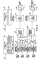
- Referring to Figure 2, this shows apparatus for concealing errors in a digital television signal. The apparatus comprises a luminance sample storage means 1 to which luminance input samples are supplied by way of an
input terminal 2. The luminance sample storage means 1 supplies outputs to a luminance sample matrix storage means 3 which stores a moving matrix of sample values corresponding to the sample positions (n+l),S2; (n+1),Sl; (n+l),SO; (n+1),S-1; (n+l),S-2; n,Sl; n,SO; n,S-1; (n-1),S2; (n-1),Sl; (n-1),S0; (n-1),S-1; and (n-1),S-2. - Four concealment accuracy detectors are provided, these being a horizontal
concealment accuracy detector 4, a verticalconcealment accuracy detector 5, a positive diagonalconcealment accuracy detector 6 and a negative diagonal concealment accuracy detector 7. Each of theconcealment accuracy detectors 4 to 7 is continuously supplied with the appropriate part of the sample matrix from the luminance sample matrix storage means 3. Thus the horizontalconcealment accuracy detector 4, for example, receives or selects the sample values necessary to calculate the concealment accuracy H using algorithm (1) above, and supplies a signal representing the concealment accuracy H by way of aweighting multiplier 8 to aluminance direction processor 12. Likewise theconcealment accuracy detectors 5 to 7 supply a respective signal representing the vertical concealment accuracy V, the positive diagonal concealment accuracy D and the negative diagonal concealment accuracy D- by way ofweighting multipliers luminance direction processor 12. Theweighting multipliers 8 to 11 effect the weighting referred to above to compensate for the different distances between adjacent sample positions in the various directions. The weighting may be done simply on the basis of distance between adjacent sample positions, in which case each weighting multiplier multiplies by the reciprocal of the distance between adjacent sample positions in the relevant direction. Other weightings can, however, be used. - The
luminance direction processor 12 supplies an output signal representing the selected direction of concealment to asample value calculator 13 which operates to select the appropriate samples from the luminance sample matrix storage means 3 and calculate therefrom the required concealment value to be used to conceal the error sample. For example, if the horizontal direction is selected, thesample value calculator 13 uses the sample values for the sample positions n,S-1 and n,S+l to calculate the value to be used to conceal the error sample at the sample position n, S0. The concealment value is supplied to a selector 14 to which a switching signal is supplied by way of a terminal 15. The selector 14 is also supplied with the sample value from the sample position n,SO by way of a terminal 16. - Preferably the apparatus as so far described operates continuously, that is to say concealment values are determined as described for every sample position and supplied to the selector 14. Only, however, when it has been determined that there is an error at a given sample position n,SO, is a signal supplied to the selector 14 by way of the terminal 15, whereupon the concealment value supplied from the
calculator 13 is supplied to aluminance output terminal 17 in place of the sample value supplied by way of the terminal 16. At all other times, the sample value supplied by way of the terminal 16 is supplied to theluminance output terminal 17. - The fact that there is an error at a given sample position n,SO can be determined in any suitable manner. For example, it may be determined that the data word representing the sample value is not valid. As a more specific example, suppose that each sample value is coded into a word in the sub-set of 10-bit words which consist of 5 "0" and 5 "1"; this being convenient for magnetic recording and reproduction because of the large number of transients and the ease of clock recovery. In this case any reproduced data word not having 5 "0" and 5 "1" is not a valid member of the sub-set and so is clearly an error. Thereupon a switching signal is supplied to the terminal 15.
- The apparatus may also include arrangements for calculating concealment values for the colour difference channels U and V. For simplicity, only that part of the apparatus necessary to calculate concealment values for the difference channel U is shown and will be described. For this purpose the apparatus comprises a chrominance sample storage means 21 to which chrominance input samples are supplied by way of an
input terminal 22. The chrominance sample storage means 21 supplies outputs to a chrominance signal matrix storage means 23 which stores a moving matrix of sample values corresponding to those listed above in connection with the luminance sample matrix storage means 3, but adjusted to take account of the different spacing between adjacent chrominance samples. - Operating in time division multiplex for the luminance and chrominance samples respectively, the
concealment accuracy detectors 4 to 7 derive signals representing the horizontal, vertical, positive diagonal and negative diagonal concealment accuracies H, V, V+ and V- for the chrominance difference channel U and supply the signals by way of respectivechrominance weighting multipliers chrominance direction processor 28 which supplies an output signal representing the selected direction of concealment to asample value calculator 29 which operates to select the appropriate samples from the chrominance sample matrix storage means 23 and calculate therefrom the required concealment value to be used to conceal the error sample. The concealment error is supplied to aselector 30 to which a switching signal is supplied by way of a terminal 31. Theselector 30 is also supplied with the sample value from the sample position n,SO by way of a terminal 32. - As with the luminance part of the apparatus, the chrominance part of the apparatus preferably operates continuously. Only, however, when it has been determined there is an error at a given sample position n,SO, is a signal supplied to the
selector 30 by way of the terminal 31, whereupon the concealment value supplied from thecalculator 29 is supplied to achrominance output terminal 33 in place of the sample value supplied by way of the terminal 32. - The chrominance part of apparatus may be duplicated for the colour difference channel V or alternatively hardware can be saved by also using the algorithm selected for the colour difference channel U for the colour difference channel V.
- The method described above may be modified as described in our co- pending UK patent application no. 8214086 (Serial No. ), to steer the algorithms used to avoid samples known to be in error when calculating sample values for replacement.
- Briefly, this is done by calculating each of the concealment accuracies defined by expressions (1) to (4) in two component parts corresponding respectively to the first and second lines of each of expressions (1) to (4). Any calculation involving the use of an error sample is rejected so, depending on the density of errors, a concealment accuracy may be calculated using sample values on one side or the other side or both sides of the sample to be concealed. With this modified method therefore the algorithms are steered to avoid error samples using the fact that eight different calculations for concealment accuracies are available.
- During reproduction at normal speed the method described above or the modified method mentioned above works well, because at least some valid samples are generally available adjacent to any sample needing concealment. Moreover, the probability of valid adjacent samples being available can be increased by shuffling the order of the samples before recording or transmission and de-shuffling after reproduction or reception, this dispersing any sequence of lost or corrupted samples resulting from a short drop-out. When high speed shuttle modes of reproduction are used, that is where the tape transport speed is varied over a wide range from a multiple of (say up to twenty times) the normal speed in the forward direction to a similar speed in the reverse direction, very severe loss and corruption of reproduced sources inevitably occurs due to the reproducing head crossing from recording track to recording track rather than correctly tracing each recording track in sequence. This results in noise bars on the reproduced picture.
- This problem can be alleviated to some extent by including a field store to provide replacement samples on the time axis. In the field store are stored, as available, correct samples or corrected samples, or failing that the above corrected values forming concealment samples. The data for each sample position is up-dated as and when possible by over-writing the new data in the respective sample positions. Each recently entered data word has a flag bit attached to it indicating that it is recent data. Particularly at the higher reproduction speeds such up-dating will become infrequent at least for some sample positions, and because normally whole blocks of data words are lost and because the shuffling and de-shuffling process normally used disperses the individual words of each such block over the picture area, the resulting effect on the reproduced picture is called "trailing dots". Quite simply, the effect is due to old data being used at some of the sample positions. The trailing dots effect is particularly objectionable in the case of a reproduced picture containing any rapid movement, and results in a very hazy image.
- In embodiments of the present invention this problem is alleviated by the use of at least the first of two further measures, these being; sample replacement in one direction, which can be modified to include the step of selecting the direction, and limiting the number of successive samples replaced.
- Sample replacement will first be described with reference to Figure 3 which shows part of a television raster, and in particular the sample positions in parts of three consecutive horizontal scan lines as they appear on the picture raster. S0,0 designates the current sample position in respect of which a sample value is about to be written into the field store, S0,-1 and S0,-2 the two previous samples in the same line, S-1,0 the corresponding sample in the previous line, and so on.
- When the previously described sample concealment using algorithms is not possible because of the high density of error samples, for example in the shuttle mode, then sample replacement is used. In general, sample replacement from any one of four points is possible, these being the sample values at those four of the adjacent sample positions in respect of which sample values have already been written into the field store. Thus if sample replacement is required at the sample position S0,0, then the replacement sample value used may be taken from S0,-1, S-1,-1, S-1,0 or S-1,1. Of these, the sample value at S0,-1 will generally give the best result, and the system may operate always to replace from that position, that is from the immediately preceding sample position in the same line. In some cases this may need to be modified to replacement from a preceding sample position, rather than the immediately preceding sample position, in the same line. For example, in some cases where the samples are shuffled in order prior to recording or transmission and are de-shuffled on reproduction or reception, it is the practice after de-shuffling to add error flags to the two samples in the same line positioned one on each side of any sample having an error flag. In such a case the system may operate always to replace from the immediately preceding sample position but one in the same line, that is, from the position S0,-2. However, the system may alternatively always operate to replace from some other adjacent position, and this alternative may in some circumstances give better results.
- In all these cases the trailing dots problem is substantially eliminated because the effect of "smearing" the samples in time is avoided. That is to say, the replacement samples used are up-to-date and are displaced in space rather than being out-of-date samples in the correct position. While therefore there is some loss of resolution, the resulting television picture is dynamically more acceptable. This is particularly important when a high speed shuttle mode is being used to search for a particular piece of action.
- As indicated above, the sample replacement process can operate in an adaptive manner by including the step of selecting the direction used for sample replacement, rather than always replacing from the same predetermined direction.
- In this case, using principles similar to those used in the adaptive concealment described above, a decision process can be used to estimate the preferred direction to be used for sample replacement. Considering, as before, the horizontal, vertical, positive diagonal and negative diagonal directions (A, B, C and D respectively in Figure 2), then respective accuracy factors EH, EV, ED+ and ED- can be calculated as follows:


- KH, KV and KD are respective spatial weighting coefficients which are proportional to the distances between the two sample positions used in the respective expression (5), (6) or (7) and (8), and Kh, Kv, Kd+ and Kd- are respective error weighting coefficients.
- The lowest value of accuracy factor EH, EV, ED+ or ED- determines the direction to be used for sample replacement.
- The error weighting coefficients Kh, Kv, Kd+ and Kd- are evaluated from the following decision table, which is given for the horizontal error weighting coefficient Kh, and the adaption of the decision table for the other three error weighting coefficients will be readily apparent:

- 0 indicates an error
- 1 indicates no error.
- Finally, as mentioned above, a limit can be placed on the number of successive samples that are replaced. Thus, if, for example, replacement is being effected using the preceding sample in the same line, then if a succession of incoming samples to the field store have error flags, then the same sample value will be successively used in a sequence of sample positions, extending along a horizontal scan line until such time as an incoming sample not having an error flag is received. The result as seen on the television picture is particularly objectionable if this occurs at the beginning of a horizontal scan line, because the first replacement sample will be taken from the front porch (the synch signal not being present in the digitized signal), and the consequence will be a black line extending across the television picture.
- To overcome this problem a counter is provided to count successive sample replacements, the counter being reset to zero each time a non-error sample value is accepted into the field store. When the count in the counter reaches a predetermined value, for example, ten, replacement of the sample is inhibited, and the counter is reset to zero. The consequence of this is that instead of using an up-to-date but spatially displaced sample value as a replacement for the error sample, the out-of-date sample value for that same position and already in the field store is used.
- Alternatively, the counter may not be reset at the count of ten, but may remain at ten until reset by an incoming non-error sample. In other words, once started, use of the previous field sample values continues until a valid current-field sample is received.
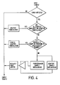
- Figure 4, to which reference is now made, shows the decision tree for the total concealment process. The decisions referred to are made by a programmable read-only memory which may conveniently be incorporated in or form the luminance sample matrix storage means 3 of Figure 2. For each input sample to the field store the first decision step is to determine whether the sample has an error flag or not. If not, the input sample itself is used as the output sample and is written at the appropriate address in the field store. If the input sample has an error flag then the process passes to the second decision step.
- In the second decision step a decision is made as to whether all the samples are available for adaptive concealment as described above in connection with expressions (1) to (4). If therefore the samples are available, then this form of adaptive concealment is used and the algorithms are used to determine the preferred direction for calculating a corrected sample value to be substituted for the input sample and written at the appropriate address in the field store. If not all the samples are available for adaptive concealment in this way then the process passes to the third decision step.
- In the third decision step a decision is made as to whether the algorithms used for calculating the concealment accuracies can be steered clear of errors as outlined above and as described in detail in our above-mentioned copending UK patent application no. 8214086 (Serial no.
- ). If the algorithms, or at least one of them can be steered to avoid error samples, then limited adaptive concealment is possible and a sample value is calculated using the direction determined from the available concealment accuracy or accuracies and this calculated sample value is used to replace the input sample and is written at the appropriate address in the field store. If the error density is such that it is not possible to steer the algorithms clear of error samples, then sample replacement as described above is used.
- As indicated in the decision tree, sample replacement may be either predetermined or adaptive sample replacement. In the case of predetermined sample replacement the replacement is always made from the same position relative to the position of the input sample. In adaptive sample replacement, the direction from which a sample value is to be taken to replace the input sample is determined as described above in connection with expressions (5) to (8).
- In either case of sample replacement, the number of successive samples replaced is counted by a counter which forms a replacement limiter. Thus, as described above, the number of successive sample replacements is limited to a predetermined value and on reaching this predetermined value the concealment process is further modified to make use of the sample value already present in the field store and belonging to an earlier field.
- It will be noted that the invention is not limited to any particular television system. Moreover, the invention is not limited to concealment of errors which have arisen in the course of recording and reproducing from a video tape recorder, but may be used in any situation where errors have arisen in processing, transmitting or handling a digital television signal.
The values of K given in the last column are generally predetermined, but can be adjusted to suit particular systems or circumstances. If the result is that all of Kh9 Kv, Kd+ and Kd- are zero, then the horizontal direction is used for sample replacement.
Claims (12)
characterised in that:


characterised by:


Priority Applications (1)
| Application Number | Priority Date | Filing Date | Title |
|---|---|---|---|
| AT83302610T ATE36210T1 (en) | 1982-05-26 | 1983-05-09 | METHODS AND DEVICES FOR FAULT CONCEALING IN DIGITAL TELEVISION SIGNALS. |
Applications Claiming Priority (2)
| Application Number | Priority Date | Filing Date | Title |
|---|---|---|---|
| GB8215359 | 1982-05-26 | ||
| GB08215359A GB2121642B (en) | 1982-05-26 | 1982-05-26 | Error concealment in digital television signals |
Publications (3)
| Publication Number | Publication Date |
|---|---|
| EP0095838A2 true EP0095838A2 (en) | 1983-12-07 |
| EP0095838A3 EP0095838A3 (en) | 1985-09-18 |
| EP0095838B1 EP0095838B1 (en) | 1988-08-03 |
Family
ID=10530636
Family Applications (1)
| Application Number | Title | Priority Date | Filing Date |
|---|---|---|---|
| EP83302610A Expired EP0095838B1 (en) | 1982-05-26 | 1983-05-09 | Methods of and apparatus for error concealment in digital television signals |
Country Status (7)
| Country | Link |
|---|---|
| US (1) | US4586082A (en) |
| EP (1) | EP0095838B1 (en) |
| JP (1) | JPS58207781A (en) |
| AT (1) | ATE36210T1 (en) |
| CA (1) | CA1217268A (en) |
| DE (1) | DE3377610D1 (en) |
| GB (1) | GB2121642B (en) |
Cited By (2)
| Publication number | Priority date | Publication date | Assignee | Title |
|---|---|---|---|---|
| EP0179560A1 (en) * | 1984-09-18 | 1986-04-30 | Sony Corporation | Error concealment in digital television signals |
| EP0197453A1 (en) * | 1985-03-29 | 1986-10-15 | Siemens Aktiengesellschaft | Method for improving the picture quality of DPCM-coded picture signals |
Families Citing this family (24)
| Publication number | Priority date | Publication date | Assignee | Title |
|---|---|---|---|---|
| JPS5970091A (en) * | 1982-10-13 | 1984-04-20 | Nippon Kogaku Kk <Nikon> | Electronic still camera |
| DE3371847D1 (en) * | 1983-07-29 | 1987-07-02 | Hell Rudolf Dr Ing Gmbh | Method and apparatus for minimizing errors during the digital processing of electric signals |
| JPS60152187A (en) * | 1984-01-19 | 1985-08-10 | Sony Corp | Interpolating device of signal |
| GB2163619A (en) * | 1984-08-21 | 1986-02-26 | Sony Corp | Error concealment in digital television signals |
| US4776031A (en) * | 1985-03-29 | 1988-10-04 | Canon Kabushiki Kaisha | Image reading apparatus |
| JPS62266987A (en) * | 1986-05-15 | 1987-11-19 | Sony Corp | Correction device for two dimensional digital signal |
| US4698685A (en) * | 1986-05-28 | 1987-10-06 | Rca Corporation | Apparatus and method for correcting CCD pixel nonuniformities |
| DE3636077C2 (en) * | 1986-10-23 | 1993-10-07 | Broadcast Television Syst | Method for masking errors in a video signal and circuit for carrying out the method |
| CA1297983C (en) * | 1986-11-12 | 1992-03-24 | Shigenobu Kasuya | Binary signal producing apparatus for optical character recognition |
| JP3018366B2 (en) * | 1989-02-08 | 2000-03-13 | ソニー株式会社 | Video signal processing circuit |
| US5838834A (en) * | 1991-11-07 | 1998-11-17 | Canon Kabushiki Kaisha | Image processing apparatus and method for quantizing image data and quantization errors using single quantizing unit and pluralities of quantization tables |
| JP2962053B2 (en) * | 1992-06-25 | 1999-10-12 | 松下電器産業株式会社 | Signal processing device |
| US6028961A (en) * | 1992-07-31 | 2000-02-22 | Canon Kabushiki Kaisha | Image processing method and apparatus |
| DE69331126T2 (en) * | 1992-07-31 | 2002-06-20 | Canon Kk | Image processing device and method for multi-stage compression |
| IL121521A (en) | 1997-08-11 | 2003-04-10 | Nds Ltd | Television signal glitch detector |
| US6621936B1 (en) | 1999-02-12 | 2003-09-16 | Sony Corporation | Method and apparatus for spatial class reduction |
| US6519369B1 (en) | 1999-02-12 | 2003-02-11 | Sony Corporation | Method and apparatus for filter tap expansion |
| US6418548B1 (en) | 1999-02-12 | 2002-07-09 | Sony Corporation | Method and apparatus for preprocessing for peripheral erroneous data |
| US6307979B1 (en) | 1999-02-12 | 2001-10-23 | Sony Corporation | Classified adaptive error recovery method and apparatus |
| US6363118B1 (en) * | 1999-02-12 | 2002-03-26 | Sony Corporation | Apparatus and method for the recovery of compression constants in the encoded domain |
| US6549672B1 (en) * | 1999-06-29 | 2003-04-15 | Sony Corporation | Method and apparatus for recovery of encoded data using central value |
| US6351494B1 (en) | 1999-09-24 | 2002-02-26 | Sony Corporation | Classified adaptive error recovery method and apparatus |
| US6522785B1 (en) | 1999-09-24 | 2003-02-18 | Sony Corporation | Classified adaptive error recovery method and apparatus |
| US6754371B1 (en) | 1999-12-07 | 2004-06-22 | Sony Corporation | Method and apparatus for past and future motion classification |
Citations (3)
| Publication number | Priority date | Publication date | Assignee | Title |
|---|---|---|---|---|
| US4250521A (en) * | 1979-07-19 | 1981-02-10 | Rca Corporation | Video signal dropout compensator |
| GB2061665A (en) * | 1979-09-29 | 1981-05-13 | Sony Corp | Digital video signal processing |
| EP0037212A2 (en) * | 1980-04-02 | 1981-10-07 | Sony Corporation | Methods and apparatuses for concealing error sample signals in digital television signals |
Family Cites Families (7)
| Publication number | Priority date | Publication date | Assignee | Title |
|---|---|---|---|---|
| US3697948A (en) * | 1970-12-18 | 1972-10-10 | Ibm | Apparatus for correcting two groups of multiple errors |
| JPS5138526A (en) * | 1974-09-25 | 1976-03-31 | Kogyo Gijutsuin | Hannoseitansoseni tosono seizohoho |
| GB2008888B (en) * | 1977-10-27 | 1982-06-30 | Quantel Ltd | Drop-out compensation system |
| GB2084432A (en) * | 1980-09-18 | 1982-04-07 | Sony Corp | Error concealment in digital television signals |
| DE3114275A1 (en) * | 1981-04-09 | 1982-11-04 | Robert Bosch Gmbh, 7000 Stuttgart | METHOD AND CIRCUIT ARRANGEMENT FOR HIDDEN ERRORS IN A DIGITAL VIDEO SIGNAL |
| DE3121599C2 (en) * | 1981-05-30 | 1986-11-27 | Robert Bosch Gmbh, 7000 Stuttgart | Method and circuit arrangement for concealing errors in a digital video signal |
| US4470065A (en) * | 1982-03-25 | 1984-09-04 | Rca Corporation | Adaptive error concealment using horizontal information determination from adjacent lines |
-
1982
- 1982-05-26 GB GB08215359A patent/GB2121642B/en not_active Expired
-
1983
- 1983-05-09 DE DE8383302610T patent/DE3377610D1/en not_active Expired
- 1983-05-09 AT AT83302610T patent/ATE36210T1/en not_active IP Right Cessation
- 1983-05-09 EP EP83302610A patent/EP0095838B1/en not_active Expired
- 1983-05-11 CA CA000427954A patent/CA1217268A/en not_active Expired
- 1983-05-18 US US06/495,684 patent/US4586082A/en not_active Expired - Lifetime
- 1983-05-20 JP JP58089882A patent/JPS58207781A/en active Granted
Patent Citations (3)
| Publication number | Priority date | Publication date | Assignee | Title |
|---|---|---|---|---|
| US4250521A (en) * | 1979-07-19 | 1981-02-10 | Rca Corporation | Video signal dropout compensator |
| GB2061665A (en) * | 1979-09-29 | 1981-05-13 | Sony Corp | Digital video signal processing |
| EP0037212A2 (en) * | 1980-04-02 | 1981-10-07 | Sony Corporation | Methods and apparatuses for concealing error sample signals in digital television signals |
Cited By (2)
| Publication number | Priority date | Publication date | Assignee | Title |
|---|---|---|---|---|
| EP0179560A1 (en) * | 1984-09-18 | 1986-04-30 | Sony Corporation | Error concealment in digital television signals |
| EP0197453A1 (en) * | 1985-03-29 | 1986-10-15 | Siemens Aktiengesellschaft | Method for improving the picture quality of DPCM-coded picture signals |
Also Published As
| Publication number | Publication date |
|---|---|
| EP0095838B1 (en) | 1988-08-03 |
| EP0095838A3 (en) | 1985-09-18 |
| DE3377610D1 (en) | 1988-09-08 |
| ATE36210T1 (en) | 1988-08-15 |
| GB2121642A (en) | 1983-12-21 |
| CA1217268A (en) | 1987-01-27 |
| JPH0479193B2 (en) | 1992-12-15 |
| GB2121642B (en) | 1985-11-27 |
| JPS58207781A (en) | 1983-12-03 |
| US4586082A (en) | 1986-04-29 |
Similar Documents
| Publication | Publication Date | Title |
|---|---|---|
| EP0095838B1 (en) | Methods of and apparatus for error concealment in digital television signals | |
| EP0048569B1 (en) | Error concealment in digital television signals | |
| EP0179560B1 (en) | Error concealment in digital television signals | |
| EP0065365B1 (en) | Digital television apparatus | |
| EP0037212B1 (en) | Methods and apparatuses for concealing error sample signals in digital television signals | |
| US5142537A (en) | Video signal processing circuit | |
| US4656514A (en) | Error concealment in digital television signals | |
| US4605966A (en) | Error concealment in digital television signals | |
| EP0415699B1 (en) | Digital video signal recorder and reproducer | |
| EP0102782A2 (en) | Error correction in digital television signals | |
| US5231680A (en) | Horizontal adaptive error concealment system for component digital television signals | |
| GB2227900A (en) | Datv encoding and decoding | |
| EP0478040A2 (en) | Four direction adaptive error concealment system for component digital television signals | |
| EP0492725B1 (en) | Horizontal adaptive error concealment system for component digital television signals |
Legal Events
| Date | Code | Title | Description |
|---|---|---|---|
| PUAI | Public reference made under article 153(3) epc to a published international application that has entered the european phase |
Free format text: ORIGINAL CODE: 0009012 |
|
| AK | Designated contracting states |
Designated state(s): AT DE FR GB NL |
|
| PUAL | Search report despatched |
Free format text: ORIGINAL CODE: 0009013 |
|
| AK | Designated contracting states |
Designated state(s): AT DE FR GB NL |
|
| 17P | Request for examination filed |
Effective date: 19860205 |
|
| 17Q | First examination report despatched |
Effective date: 19871130 |
|
| GRAA | (expected) grant |
Free format text: ORIGINAL CODE: 0009210 |
|
| AK | Designated contracting states |
Kind code of ref document: B1 Designated state(s): AT DE FR GB NL |
|
| REF | Corresponds to: |
Ref document number: 36210 Country of ref document: AT Date of ref document: 19880815 Kind code of ref document: T |
|
| REF | Corresponds to: |
Ref document number: 3377610 Country of ref document: DE Date of ref document: 19880908 |
|
| ET | Fr: translation filed | ||
| PLBE | No opposition filed within time limit |
Free format text: ORIGINAL CODE: 0009261 |
|
| STAA | Information on the status of an ep patent application or granted ep patent |
Free format text: STATUS: NO OPPOSITION FILED WITHIN TIME LIMIT |
|
| 26N | No opposition filed | ||
| REG | Reference to a national code |
Ref country code: GB Ref legal event code: IF02 |
|
| PGFP | Annual fee paid to national office [announced via postgrant information from national office to epo] |
Ref country code: GB Payment date: 20020508 Year of fee payment: 20 |
|
| PGFP | Annual fee paid to national office [announced via postgrant information from national office to epo] |
Ref country code: AT Payment date: 20020523 Year of fee payment: 20 |
|
| PGFP | Annual fee paid to national office [announced via postgrant information from national office to epo] |
Ref country code: FR Payment date: 20020529 Year of fee payment: 20 |
|
| PGFP | Annual fee paid to national office [announced via postgrant information from national office to epo] |
Ref country code: NL Payment date: 20020531 Year of fee payment: 20 |
|
| PGFP | Annual fee paid to national office [announced via postgrant information from national office to epo] |
Ref country code: DE Payment date: 20020730 Year of fee payment: 20 |
|
| PG25 | Lapsed in a contracting state [announced via postgrant information from national office to epo] |
Ref country code: GB Free format text: LAPSE BECAUSE OF EXPIRATION OF PROTECTION Effective date: 20030508 |
|
| PG25 | Lapsed in a contracting state [announced via postgrant information from national office to epo] |
Ref country code: NL Free format text: LAPSE BECAUSE OF EXPIRATION OF PROTECTION Effective date: 20030509 Ref country code: AT Free format text: LAPSE BECAUSE OF EXPIRATION OF PROTECTION Effective date: 20030509 |
|
| REG | Reference to a national code |
Ref country code: GB Ref legal event code: PE20 |
|
| NLV7 | Nl: ceased due to reaching the maximum lifetime of a patent |
Effective date: 20030509 |