EP0077843A1 - Handle bag making apparatus - Google Patents
Handle bag making apparatus Download PDFInfo
- Publication number
- EP0077843A1 EP0077843A1 EP81108928A EP81108928A EP0077843A1 EP 0077843 A1 EP0077843 A1 EP 0077843A1 EP 81108928 A EP81108928 A EP 81108928A EP 81108928 A EP81108928 A EP 81108928A EP 0077843 A1 EP0077843 A1 EP 0077843A1
- Authority
- EP
- European Patent Office
- Prior art keywords
- web
- bag making
- making apparatus
- cutting
- segment
- Prior art date
- Legal status (The legal status is an assumption and is not a legal conclusion. Google has not performed a legal analysis and makes no representation as to the accuracy of the status listed.)
- Granted
Links
Images


Classifications
-
- B—PERFORMING OPERATIONS; TRANSPORTING
- B65—CONVEYING; PACKING; STORING; HANDLING THIN OR FILAMENTARY MATERIAL
- B65H—HANDLING THIN OR FILAMENTARY MATERIAL, e.g. SHEETS, WEBS, CABLES
- B65H35/00—Delivering articles from cutting or line-perforating machines; Article or web delivery apparatus incorporating cutting or line-perforating devices, e.g. adhesive tape dispensers
- B65H35/04—Delivering articles from cutting or line-perforating machines; Article or web delivery apparatus incorporating cutting or line-perforating devices, e.g. adhesive tape dispensers from or with transverse cutters or perforators
-
- B—PERFORMING OPERATIONS; TRANSPORTING
- B31—MAKING ARTICLES OF PAPER, CARDBOARD OR MATERIAL WORKED IN A MANNER ANALOGOUS TO PAPER; WORKING PAPER, CARDBOARD OR MATERIAL WORKED IN A MANNER ANALOGOUS TO PAPER
- B31B—MAKING CONTAINERS OF PAPER, CARDBOARD OR MATERIAL WORKED IN A MANNER ANALOGOUS TO PAPER
- B31B70/00—Making flexible containers, e.g. envelopes or bags
-
- B—PERFORMING OPERATIONS; TRANSPORTING
- B31—MAKING ARTICLES OF PAPER, CARDBOARD OR MATERIAL WORKED IN A MANNER ANALOGOUS TO PAPER; WORKING PAPER, CARDBOARD OR MATERIAL WORKED IN A MANNER ANALOGOUS TO PAPER
- B31B—MAKING CONTAINERS OF PAPER, CARDBOARD OR MATERIAL WORKED IN A MANNER ANALOGOUS TO PAPER
- B31B2155/00—Flexible containers made from webs
- B31B2155/003—Flexible containers made from webs starting from tubular webs
-
- B—PERFORMING OPERATIONS; TRANSPORTING
- B31—MAKING ARTICLES OF PAPER, CARDBOARD OR MATERIAL WORKED IN A MANNER ANALOGOUS TO PAPER; WORKING PAPER, CARDBOARD OR MATERIAL WORKED IN A MANNER ANALOGOUS TO PAPER
- B31B—MAKING CONTAINERS OF PAPER, CARDBOARD OR MATERIAL WORKED IN A MANNER ANALOGOUS TO PAPER
- B31B2160/00—Shape of flexible containers
- B31B2160/10—Shape of flexible containers rectangular and flat, i.e. without structural provision for thickness of contents
-
- B—PERFORMING OPERATIONS; TRANSPORTING
- B31—MAKING ARTICLES OF PAPER, CARDBOARD OR MATERIAL WORKED IN A MANNER ANALOGOUS TO PAPER; WORKING PAPER, CARDBOARD OR MATERIAL WORKED IN A MANNER ANALOGOUS TO PAPER
- B31B—MAKING CONTAINERS OF PAPER, CARDBOARD OR MATERIAL WORKED IN A MANNER ANALOGOUS TO PAPER
- B31B70/00—Making flexible containers, e.g. envelopes or bags
- B31B70/14—Cutting, e.g. perforating, punching, slitting or trimming
Definitions
- the present invention relates to the manufacture of thermoplastic bags and more particularly to bags incorporating hand or arm receiving handles.
- T shirt bags Bags having the configuration of the bags produced by the subject matter of the present invention are generally referred to as "T shirt bags".
- the construction essentially comprises the creation of inwardly directed folds or gussets in tubular web material which is sealed and cut at regularly spaced intervals to produce an envelope or a pillow having each end heat sealed.
- Some existing procedures transport the envelope to a stacking station which may include upstanding members, such as fences, to accumulate successive gusseted and sealed envelopes to create a stack.
- a stacking station which may include upstanding members, such as fences, to accumulate successive gusseted and sealed envelopes to create a stack.
- a press having a knife shaped to remove a generally rectangular portion from the stack of web segments. The knife cuts through the stack of web segments such that the inner extremity of the gussets and a portion of one of the transverse seals is severed, thereby creating loops which can be grasped by hand or receive the forearm of a user.
- Methods and machinery are presently available for improving stack registration by interconnecting the web segments along the trailing or leading edge to maintain stack registration during manual pickoff and punching.
- Two known approaches are used. One involves providing heated pins or bars located adjacent the sealing station that are effective to tack weld or block the stack as it is being generated. The second approach involves a heated bar in contact with one marginal edge of the welded web segments to unify the successive segments as a stack is being created. To effect this association of web segments tack welding sometimes is restricted to the area of the bag edge which will be punched or cut out when the final stage of producing a T shirt bag is accomplished.
- Certain approaches extend the tacking area of the successive bags along the entire margin of the web segment so that even after removing a rectangular segment, all of the bags are unified along the remaining edge portions. Whether heated pins are used or a heated blocking bar, the manual operation of removing the bag stack from the stacking table to the punching machine requires manual effort in removing the unified or blocked stack of bags from the bag making machine to the punching unit.
- T shirt bag operations have resorted to cutting the rectangular segment from the stack of web segments on the bag machine.
- the present state of the art incorporates rotary dies downstream of the seal bar to produce the rectangular cutouts.
- This approach does fulfill the requirements of a high quality bag (one in which the rectangular cutout is cleanly made and accurately positioned) but the rotary dies and the machine elements supporting and rotating the dies are exceedingly expensive to insure proper continuous operation and on changing bag size, replacement of the rotary dies is an expensive alteration.
- a principle feature relating to the general construction and mode of operation of the present invention comprises means, synchronously operated with a bag machine associated therewith, for removing a portion of a web segment defining a bag from a predetermined location relative to the margins of such a segment, whereby the removing means operates within the time span within which the web segment is being severed and sealed by the bag making machine.
- the means for removing a portion of the web is adjustable to assume a fixed location with respect to the sealing severing mechanism of the bag machine in order to facilitate the production of bags of the same style but of different lengths.
- the portion of the web removed from the advanced web segment is conveniently disposed out of line of the web path by providing a scrap conveyor for receiving and transporting the cutout portion of the web transversely of the machine.
- a system of bag transporting conveyor belts enhanced maintaining the completed bag in a fixed position thereby insuring fold lines or creases to assume coordinate locations with respect to the margins of the bag.
- a T shirt bag making apparatus is generally indicated by the numeral 10, and is cooperatively integrated with the operation of a bag machine of the general type shown in United States Patent No. 3,663,338.
- the bag machine incorporates a twin sealing device 12, details of which are shown in United States Patent No. 4,019,947.
- Draw rolls 14, intermittently rotated by the bag machine advance a selected segment of gusseted web W between the sealing device 12 toward a reciprocating punching mechanism 16 that removes a generally rectangular web portion from the leading portion of the advanced web segment.
- Upper and lower transversely spaced conveying means 18 and 20, respectively, direct and assist in properly positioning each web segment relative to the mechanism 16 and thereafter transport the completed bag to folding means 22.
- the folded bag is then discharged to a carton or other suitable container supported on an indexable belt 24.
- the belt 24 may incorporate spaced upstanding fences 26 which, when positioned at the discharge at the folding means 22 define a stacking station 28 confining the folded bags to assume a stack.
- the punching mechanism 16 for cutting and removing a generally rectangular slug of material from the leading portion of the web segment or segments being fed, is positionable longitudinally relative to the seal bar 12 to insure that the rectangular slug removed thereby includes cuts penetrating the inward folds of the gussets and the leading seal at spaced intervals.
- Figure 1A illustrates the cutting operation wherein a typical T shirt bag 30 is formed with inwardly extending gussets having a crease line terminating at 32. Both ends of the bag are sealed along lines 34 and a small portion of web material, usually referred to as a skirt 36, extends beyond the transverse zone of the seal 34.
- the cutout C.O. takes the form of longitudinal incisions 38, cutting the skirt 36, the seal 34 and the inner crease of the gussets 32.
- the incisions 38 are interconnected by a transverse incision 40 thereby separating the cutout from the web segment and accordingly producing a T shirt bag.
- the reciprocating mechanism 16 for making the cutouts or removing a generally rectangular portion of material from the leading portion of the web segment operates within the time in which the seal bar 12 is creating the seals and severing the advanced web segment.
- the mechanism 16 is positioned longitudinally relative to the seal bar 12 to produce T shirt bags of desired length.
- Figures 2, 3, 4 and 5 illustrate the constructional features of the reciprocating mechanism 16.
- the preferred construction includes mechanisms for translating the position of the mechanism 16 with respect to the seal bar, depending upon the length of the bag to be made. Translation is achieved by providing transversely aligned and spaced upstanding plates 42 having rigidly mounted at the upper edge and on the inner surface, gear racks 44 meshing with gears 46 mounted on a shaft 48 which is rotated by a hand wheel 50 secured to a lateral extension of the shaft 48.
- the upper edge of the plates 42 provide a support for a box-like structure 52 comprising an upper plate 54 formed with downturned portions 56 to thereby form a transversely extending channel (Figure 5).
- the reciprocating mechanism 16 is a "2-up head" meaning that two webs are simultaneously processed. Accordingly, the mechanism 16 is constructed to simultaneously process two webs and this is accomplished by providing duplicate (in construction and mode of operation) cutting positions 70 and 72. Accordingly, in describing the reciprocating mechanism 16, it is to be understood that interchangeable reference may be made with respect to the cutting positions 70 and 72.
- the cutting and removing of a generally rectangular portion from the thermoplastic web meets the objective of providing a self contained assembly which can be moved forward or away from the seal bar 12 in response to the length of bags desired.
- the constructional arrangement provides a mechanical drive designed to balance the dynamic forces during the cutting operation which insures longevity and trouble free operation since unbalanced forces which would tend to cause deterioration between machine elements that move relative to each other are balanced such that the net forces are reduced to an absolute minimum.
- the mechanism 16 includes an upper reciprocating platen 74 and a lower stationary platen 76.
- a series of actuators 92 and 93 are mounted in threaded bores formed in the upper platen 74.
- the rods 92a and 93a are in turn fixed to an outer presser plate 80 and a central presser plate 94.
- the rods 92a and 93a are continually biased toward an extended position either by a spring or air maintained at a selected pressure.
- the presser plate 80 is formed with a rectangular opening 82 having attached to its lower surface a compressable elastomeric strip 84 even with the opening 82.
- the upper platen carries, by means of a mounting block 86, a knife 88 formed to produce cuts along lines 38 and 40.
- the knife 88 is located adjacent to the rectangular opening 82.
- the central presser plate 94 is also provided with an elastomeric strip 96.
- the lower stationary platen 76 is formed with a generally central rectangular central opening 98 conforming in shape and size to the rectangular opening 82 in presser plate 80.
- the insert 100 is formed with a flange 102 and a central opening 104 through which, as will be presently explained, the cutout portion of web material passes for reception by a scrap conveyor 106 operating to convey scrap material transversely of the path of the gusseted web.
- the insert 100 together with the lower platen 76, provides a slot 108 for receiving the knife 88.
- the bag machine drive includes a main input shaft 110 having keyed thereon a tooth pulley 112 driving a similar pulley 114 by a timing belt 116 held in tension by an idler pulley 118.
- Pulley 114 and a pulley 122 are mounted on a clutch brake shaft 120.
- Pulley 122 drives a timing belt 124.
- the timing belt passes around an idler pulley 126 and a pulley 128 rotatably mounted on a stub shaft 130 carried by the bracket 66.
- a grooved pulley 132 driving a pulley 134 by a belt 136.
- the pulley 134 is keyed to a shaft 138 driving the scrap conveyor 106.
- the timing belt 124 is wrapped around a timing pulley 138 keyed to one of the shafts 62, thereby driving both shafts by virtue of the meshing gears 68.
- a large arc of contact of the belt 124 around the pulley 138 is achieved by idler pulleys 140 and 142.
- the pulley 142 is rotatably mounted on a short stub shaft 144 carried by the bracket 66 as shown in Figure 3.
- the upper platen 74 is driven downwardly to project the blade 88 through the portion of the web located within its projected area. Reciprocation of the platen 74 is accomplished by rigidly mounting, laterally spaced ears 146 to its upper surface and rotatably mounting therebetween, on a short pin shaft 148, a cam follower roller 150.
- the upper platen 74 is reciprocated by cams 152 and 154 ( Figure 4) rigidly secured to the shafts 62 which, as mentioned above, are concurrently driven by the belt 124 through the agency of the meshing gears 68.
- the shafts 62 and the cams associated therewith are rotated in opposite directions and therefore, the forces produced which may tend to create or impose bending moments on the platen 74 balance each other and accordingly smooth action and extended life between relatively moving surfaces result.
- the upper platen 74 is guided for rectilinear movement by guide pins 156 each of which have one end secured in the lower platen 76 and the other end fixed in an ear 158 rigid with the outer ribs 58.
- guide pins 156 each of which have one end secured in the lower platen 76 and the other end fixed in an ear 158 rigid with the outer ribs 58.
- compression springs 160 bias the platen 174 upwardly and insure that rolling contact between the cam follower rollers 150 and the cams 152 and 154 is maintained.
- the scrap conveyor 106 has a feeding reach 162 extending below both of the inserts 100 so that the punched out portion of web material may be transported laterally of feed parth of the web material.
- the scrap conveyor includes a driven roller 163 mounted on the shaft 138, idler rollers 164 and a return each diverting roller 166.
- Positive ejection of the scrap of web material cut by the knife 88 is preferably accomplished by providing a tube 188 connected to a source of pressure air and being fixed to the upper platen 74.
- the tube partially projects into the central presser plate 194.
- An enlarged opening 190 insures the diffusion of pressure air to positively remove the cutout portion of web material and propel it to the conveyor 106.
- Each of the levers 168 are formed with an integral pocket 178 in which is rotatably mounted a cam follower roller 180, held in rolling engagement with cams 176 by the springs 174. In view of this arrangement, during each cycle of operation, the levers 168 are cammed downwardly squeezing the completed bag between the belts 18 and 20 for advancement to the folding means 22.
- the upper and lower conveying means 18 and 20 respectively comprise, as shown in Figure 3, a plurality of laterally spaced relatively narrow flat belts, some of which are diverted around reciprocating unit 16 so that their path does not fall in the projected area of the knife 88 and certain of the belts are directed over the lower platen 76.
- a plurality of idler rollers all of which are collectively identified by the numeral 182
- divert belts 20a Figure 5 to pass under the cutting knife 88 while belts 20b pass over the lower platen 76.
- Diversion of the upper conveying means 18 follows a similar pattern by diverting reaches 18a while reaches 18b are adjacent the reaches 20b.
- the non-diverted reaches position the web segment properly with respect to the knife 88 and thereby insure accurate location of the cutout portion.
- All of the belts 18 diverted around the reciprocating unit 16 pass around roller 172 and are tracked as shown in Figure 5 by idler rollers 184 which are rotatably supported in end plates 186 attached in any suitable manner to the frame of the reciprocating mechanism 16.
- the leading portion of the segment is positioned within the projected area of the knife 88 to effect cutting along the longitudinal incisions 38 and the transverse incision 40 as described above.
- the twin sealing device 12 descends to effect sealing and severing of the advanced web segment.
- the reciprocating mechanism 16 descends clamping the web by presser plate 80 and the central presser plate 94 firmly clamping the web before the knife 88 cuts the web along lines 38 and 40.
- the cutout C.O. is removed by the air issuing through tube 188 after the upper platen raises, releasing the clamping pressure of the presser plate 94 and then the presser plate 80.
- the cutout portion is received on conveyor 106 and discharged.
- Completion of a bag making cycle occurs when the seal bars 12 are separated after sealing and severing of the advanced web segment has been accomplished.
- cams 176 pivot the offset levers 168 downwardly, causing the pickoff roller 172 to firmly press the belt reaches 18b and 20b together to thereby advance the compeleted bag toward the folding mechanisms 22.
- the folding mechanism comprises first and second sets of folding rolls 192 and 194, respectively.
- the bag is sequentially directed to the nip of folding rolls 192 and 194 by air issuing from air tubes 196 and 198 directing jets of air to the nip of the folding rolls.
- the bag with the single fold is directed by belts 18 between the wires 206 and a generally L shaped wire 210.
- the air tube 198 is programmed for operation by a time delay and the jets of air directed toward the nip of folding rolls 194 makes one additional fold.
- the twice folded bag is discharged to the stacking station 28.
- Figure 10 diagramatically illustrates the action of the folder 22. Upon accumulating a stack having a selected number of bags the conveyor 24 is operated to transport the bag stack away from the stacking station 28.
Abstract
Description
- The present invention relates to the manufacture of thermoplastic bags and more particularly to bags incorporating hand or arm receiving handles.
- Bags having the configuration of the bags produced by the subject matter of the present invention are generally referred to as "T shirt bags". The construction essentially comprises the creation of inwardly directed folds or gussets in tubular web material which is sealed and cut at regularly spaced intervals to produce an envelope or a pillow having each end heat sealed.
- Some existing procedures transport the envelope to a stacking station which may include upstanding members, such as fences, to accumulate successive gusseted and sealed envelopes to create a stack. Once the stack is completed, it is manually removed by the operator and further processed by a press having a knife shaped to remove a generally rectangular portion from the stack of web segments. The knife cuts through the stack of web segments such that the inner extremity of the gussets and a portion of one of the transverse seals is severed, thereby creating loops which can be grasped by hand or receive the forearm of a user.
- The above procedure involves certain disadvantages which relate to stack registration meaning that the corresponding edges of successive bags or web segments overlie each other so that the completed stack takes the form (much like a ream of paper or a deck of cards), the labor and time involved for manual removing and placing the stacks in machinery which effects cutting of the generally rectangular slug and the finished stacks do not easily lend themselves for cartoning in an organized fashion.
- Methods and machinery are presently available for improving stack registration by interconnecting the web segments along the trailing or leading edge to maintain stack registration during manual pickoff and punching. Two known approaches are used. One involves providing heated pins or bars located adjacent the sealing station that are effective to tack weld or block the stack as it is being generated. The second approach involves a heated bar in contact with one marginal edge of the welded web segments to unify the successive segments as a stack is being created. To effect this association of web segments tack welding sometimes is restricted to the area of the bag edge which will be punched or cut out when the final stage of producing a T shirt bag is accomplished.
- Certain approaches extend the tacking area of the successive bags along the entire margin of the web segment so that even after removing a rectangular segment, all of the bags are unified along the remaining edge portions. Whether heated pins are used or a heated blocking bar, the manual operation of removing the bag stack from the stacking table to the punching machine requires manual effort in removing the unified or blocked stack of bags from the bag making machine to the punching unit.
- To eliminate labor costs associated with removing bag stacks from the line and improve quality, T shirt bag operations have resorted to cutting the rectangular segment from the stack of web segments on the bag machine.
- Further improvements have resulted in machinery in which removal of the generally rectangular portion occurs as each web segment is produced by the bag making machine and thereafter folding the individual T shirt bag before stacking. The beneficial effects of this approach include reduction of stack dimension and the elimination of problems attendant with the extended grasping loops. As a result stack handling, cartoning and dispensing was considerably improved.
- In producing the cutout of the individual bags on the bag machine certain problems, principally dealing with control of the web segment and the utilization of a shaped cutting blade propelled by pneumatic cylinders arose. Removal of the rectangular section from the web before sealing produced serious wrinkling problems which diminished the quality and accordingly the acceptability of the resulting T shirt bag. Moreover, punching or severing the generally rectangular slug from the web tube before sealing and severing required extreme accuracy in order to avoid the creation of slits or slight cuts in the bottom seal. Accuracy of this magnitude is not repetitively possible and to utilize this approach required more web for each bag.
- The present state of the art incorporates rotary dies downstream of the seal bar to produce the rectangular cutouts. This approach does fulfill the requirements of a high quality bag (one in which the rectangular cutout is cleanly made and accurately positioned) but the rotary dies and the machine elements supporting and rotating the dies are exceedingly expensive to insure proper continuous operation and on changing bag size, replacement of the rotary dies is an expensive alteration.
- A principle feature relating to the general construction and mode of operation of the present invention comprises means, synchronously operated with a bag machine associated therewith, for removing a portion of a web segment defining a bag from a predetermined location relative to the margins of such a segment, whereby the removing means operates within the time span within which the web segment is being severed and sealed by the bag making machine.
- According to another feature of the present invention the means for removing a portion of the web is adjustable to assume a fixed location with respect to the sealing severing mechanism of the bag machine in order to facilitate the production of bags of the same style but of different lengths.
- According to another and equally important feature of the present invention, the means for removing a portion of the advanced web segment includes a stationary platen and a cam driven platen supporting clamping members and a knife shaped in accordance with the portion to be removed, the cam driven platen is designed to create forces that minimize bending in guide pins and bushing thereby insuring longevity and clean and accurate shearing of the web.
- According to another feature of the present invention the portion of the web removed from the advanced web segment is conveniently disposed out of line of the web path by providing a scrap conveyor for receiving and transporting the cutout portion of the web transversely of the machine. Moreover, a system of bag transporting conveyor belts, enhanced maintaining the completed bag in a fixed position thereby insuring fold lines or creases to assume coordinate locations with respect to the margins of the bag.
- The various figures of the drawing will now be described.
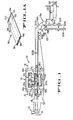
- Figure 1 is a side elevation diagramatically illustrating a T shirt bag making apparatus incorporating the novel concepts of the present invention;
- Figure lA is a perspective of a gusseted web segment and the location of cut lines;
- Figure 2 is an enlarged plan with parts broken away taken substantially along the line 2 - 2 of Figure 1;
- Figure 3 is a vertical transverse section taken substantially along the offset line 3 - 3 of Figure 2 illustrating details of the apparatus for cutting and removing a portion of material;
- Figure 4 is a perspective of the drive for the cutting mechanism;
- Figure 5 is a section of the cutting mechanism taken substantially along the lines 5 - 5 of Figure 3;
- Figures 6, 7, 8 and 9 diagramatically illustrate the sequence in cutting a portion from a gusseted web segment;
- Figure 10 pictorially illustrates one form of a T shirt bag produced by the apparatus of the present invention; and
- Figure 11 is a diagramatic perspective of the sequence of operations producing folded T shirt bags.
- With the reference now to Figure 1 for a description of the invention, a T shirt bag making apparatus, is generally indicated by the
numeral 10, and is cooperatively integrated with the operation of a bag machine of the general type shown in United States Patent No. 3,663,338. The bag machine incorporates atwin sealing device 12, details of which are shown in United States Patent No. 4,019,947.Draw rolls 14, intermittently rotated by the bag machine, advance a selected segment of gusseted web W between thesealing device 12 toward a reciprocatingpunching mechanism 16 that removes a generally rectangular web portion from the leading portion of the advanced web segment. Upper and lower transversely spaced conveying means 18 and 20, respectively, direct and assist in properly positioning each web segment relative to themechanism 16 and thereafter transport the completed bag to folding means 22. The folded bag is then discharged to a carton or other suitable container supported on anindexable belt 24. Thebelt 24 may incorporate spacedupstanding fences 26 which, when positioned at the discharge at the folding means 22 define astacking station 28 confining the folded bags to assume a stack. - The
punching mechanism 16, for cutting and removing a generally rectangular slug of material from the leading portion of the web segment or segments being fed, is positionable longitudinally relative to theseal bar 12 to insure that the rectangular slug removed thereby includes cuts penetrating the inward folds of the gussets and the leading seal at spaced intervals. Figure 1A illustrates the cutting operation wherein a typicalT shirt bag 30 is formed with inwardly extending gussets having a crease line terminating at 32. Both ends of the bag are sealed alonglines 34 and a small portion of web material, usually referred to as askirt 36, extends beyond the transverse zone of theseal 34. When a predetermined length of web segment has been fed and its leading portion is within the confines of themechanism 16, the cutout C.O. takes the form oflongitudinal incisions 38, cutting theskirt 36, theseal 34 and the inner crease of thegussets 32. Theincisions 38 are interconnected by atransverse incision 40 thereby separating the cutout from the web segment and accordingly producing a T shirt bag. Thereciprocating mechanism 16 for making the cutouts or removing a generally rectangular portion of material from the leading portion of the web segment operates within the time in which theseal bar 12 is creating the seals and severing the advanced web segment. Moreover, themechanism 16 is positioned longitudinally relative to theseal bar 12 to produce T shirt bags of desired length. - Figures 2, 3, 4 and 5 illustrate the constructional features of the
reciprocating mechanism 16. Referring first to Figure 5, the preferred construction includes mechanisms for translating the position of themechanism 16 with respect to the seal bar, depending upon the length of the bag to be made. Translation is achieved by providing transversely aligned and spacedupstanding plates 42 having rigidly mounted at the upper edge and on the inner surface, gear racks 44 meshing withgears 46 mounted on ashaft 48 which is rotated by ahand wheel 50 secured to a lateral extension of theshaft 48. The upper edge of theplates 42 provide a support for a box-like structure 52 comprising anupper plate 54 formed withdownturned portions 56 to thereby form a transversely extending channel (Figure 5). Extending between thedownturned portions 56, and attached to theplate 54 and theportions 56, are a plurality of laterally spaced downwardly extendingribs 58 in which are mounted alignedbearings 60 rotatably supportingshafts 62 extending throughclearance holes 64 formed in abracket 66. As shown in Figures 2 and 3, theshafts 62 extend beyond thebracket 66 and the ends thereof are keyed to meshinggears 68. - As shown most clearly in Figure 2, the
reciprocating mechanism 16 is a "2-up head" meaning that two webs are simultaneously processed. Accordingly, themechanism 16 is constructed to simultaneously process two webs and this is accomplished by providing duplicate (in construction and mode of operation) cuttingpositions reciprocating mechanism 16, it is to be understood that interchangeable reference may be made with respect to thecutting positions - The cutting and removing of a generally rectangular portion from the thermoplastic web, in accordance with the construction and mode of operation disclosed herein, meets the objective of providing a self contained assembly which can be moved forward or away from the
seal bar 12 in response to the length of bags desired. Moreover, the constructional arrangement provides a mechanical drive designed to balance the dynamic forces during the cutting operation which insures longevity and trouble free operation since unbalanced forces which would tend to cause deterioration between machine elements that move relative to each other are balanced such that the net forces are reduced to an absolute minimum. - To achieve the above identified objectives, the
mechanism 16 includes anupper reciprocating platen 74 and a lowerstationary platen 76. A series ofactuators upper platen 74. Therods outer presser plate 80 and acentral presser plate 94. Therods presser plate 80 is formed with arectangular opening 82 having attached to its lower surface a compressableelastomeric strip 84 even with theopening 82. The upper platen carries, by means of a mounting block 86, aknife 88 formed to produce cuts alonglines knife 88 is located adjacent to therectangular opening 82. Thecentral presser plate 94 is also provided with anelastomeric strip 96. The lowerstationary platen 76 is formed with a generally central rectangularcentral opening 98 conforming in shape and size to therectangular opening 82 inpresser plate 80. Joined to the lower platen, in any suitable manner such as by threaded fasteners or by welding and within therectangular opening 98, is aninsert 100. - As shown in Figure 5, the
insert 100 is formed with aflange 102 and acentral opening 104 through which, as will be presently explained, the cutout portion of web material passes for reception by ascrap conveyor 106 operating to convey scrap material transversely of the path of the gusseted web. Theinsert 100, together with thelower platen 76, provides aslot 108 for receiving theknife 88. - Reciprocation of the
upper platen 74 in synchronism with the operation of the bag machine is achieved by the driving arrangement shown in Figure 4. As is conventional, the bag machine drive includes amain input shaft 110 having keyed thereon atooth pulley 112 driving asimilar pulley 114 by atiming belt 116 held in tension by an idler pulley 118.Pulley 114 and apulley 122 are mounted on aclutch brake shaft 120.Pulley 122 drives atiming belt 124. In driving theshafts 62, the timing belt passes around anidler pulley 126 and apulley 128 rotatably mounted on astub shaft 130 carried by thebracket 66. Also mounted on thestub shaft 130 is a groovedpulley 132 driving apulley 134 by abelt 136. Thepulley 134 is keyed to ashaft 138 driving thescrap conveyor 106. Thetiming belt 124 is wrapped around a timingpulley 138 keyed to one of theshafts 62, thereby driving both shafts by virtue of the meshing gears 68. A large arc of contact of thebelt 124 around thepulley 138 is achieved byidler pulleys 140 and 142. Thepulley 142 is rotatably mounted on ashort stub shaft 144 carried by thebracket 66 as shown in Figure 3. - By virtue of this driving arrangement, movement of the
mechanism 16 along the upper edges of theplates 42 by means of the rack and pinion arrangement allows longitudinal movement in response to the bag size to be produced and yet the described driving arrangement can be maintained since the path of the drivingbelt 124 is maintained. - The
upper platen 74 is driven downwardly to project theblade 88 through the portion of the web located within its projected area. Reciprocation of theplaten 74 is accomplished by rigidly mounting, laterally spacedears 146 to its upper surface and rotatably mounting therebetween, on ashort pin shaft 148, acam follower roller 150. Theupper platen 74 is reciprocated bycams 152 and 154 (Figure 4) rigidly secured to theshafts 62 which, as mentioned above, are concurrently driven by thebelt 124 through the agency of the meshing gears 68. Theshafts 62 and the cams associated therewith are rotated in opposite directions and therefore, the forces produced which may tend to create or impose bending moments on theplaten 74 balance each other and accordingly smooth action and extended life between relatively moving surfaces result. - As shown in Figures 2 and 3, the
upper platen 74 is guided for rectilinear movement byguide pins 156 each of which have one end secured in thelower platen 76 and the other end fixed in anear 158 rigid with theouter ribs 58. Between the upper andlower platens pins 156, compression springs 160 bias theplaten 174 upwardly and insure that rolling contact between thecam follower rollers 150 and thecams - As shown best in Figure 3, the
scrap conveyor 106 has afeeding reach 162 extending below both of theinserts 100 so that the punched out portion of web material may be transported laterally of feed parth of the web material. The scrap conveyor includes a drivenroller 163 mounted on theshaft 138,idler rollers 164 and a return each divertingroller 166. - Positive ejection of the scrap of web material cut by the
knife 88 is preferably accomplished by providing atube 188 connected to a source of pressure air and being fixed to theupper platen 74. The tube partially projects into thecentral presser plate 194. Anenlarged opening 190 insures the diffusion of pressure air to positively remove the cutout portion of web material and propel it to theconveyor 106. - After the generally rectangular cutout has been made in the web segment, advance of the web segment to the folding means 22 is achieved by pressing the
belts levers 168 having one end pivotally connected at 170 to theoutmost ribs 58 and the other end rotatably mounting aroller 172. Theroller 172 extends for the entire length of thereciprocating unit 16. The levers are biased upwardly bysprings 174 and timed reciprocating movement downwardly compressing thebelts cams 176 mounted on theshaft 162 as shown in Figure 4. Each of thelevers 168 are formed with anintegral pocket 178 in which is rotatably mounted acam follower roller 180, held in rolling engagement withcams 176 by thesprings 174. In view of this arrangement, during each cycle of operation, thelevers 168 are cammed downwardly squeezing the completed bag between thebelts - The upper and lower conveying
means unit 16 so that their path does not fall in the projected area of theknife 88 and certain of the belts are directed over thelower platen 76. To effect diversion of selected belts, a plurality of idler rollers, all of which are collectively identified by the numeral 182, divertbelts 20a (Figure 5) to pass under the cuttingknife 88 whilebelts 20b pass over thelower platen 76. Diversion of the upper conveyingmeans 18 follows a similar pattern by divertingreaches 18a whilereaches 18b are adjacent thereaches 20b. The non-diverted reaches position the web segment properly with respect to theknife 88 and thereby insure accurate location of the cutout portion. All of thebelts 18 diverted around thereciprocating unit 16 pass aroundroller 172 and are tracked as shown in Figure 5 byidler rollers 184 which are rotatably supported inend plates 186 attached in any suitable manner to the frame of thereciprocating mechanism 16. - In operation, when a web segment is advanced by the draw folls 14, the leading portion of the segment is positioned within the projected area of the
knife 88 to effect cutting along thelongitudinal incisions 38 and thetransverse incision 40 as described above. With the fed web segment at rest, thetwin sealing device 12 descends to effect sealing and severing of the advanced web segment. During a portion of the time required to effect sealing thereciprocating mechanism 16 descends clamping the web bypresser plate 80 and thecentral presser plate 94 firmly clamping the web before theknife 88 cuts the web alonglines tube 188 after the upper platen raises, releasing the clamping pressure of thepresser plate 94 and then thepresser plate 80. The cutout portion is received onconveyor 106 and discharged. - The above sequence of operations is illustrated in Figures 6 - 9 wherein the leading portion of the web segment is shown clamped between the
presser plates central presser plate 94. Continued rotation of theshafts 62 displaces theupper platen 74 to its downward limit and thereby effects cutting of the web segment alonglines shaft 62 raises theupper platen 74 releasing the clamping pressure of the web segment. Air introduced through thetube 188 blows the cutout portion toward aconveyor 106 while thepresser plate 80 is still in contact with thelower platen 76. - Completion of a bag making cycle occurs when the seal bars 12 are separated after sealing and severing of the advanced web segment has been accomplished. At this time,
cams 176 pivot the offsetlevers 168 downwardly, causing thepickoff roller 172 to firmly press the belt reaches 18b and 20b together to thereby advance the compeleted bag toward the foldingmechanisms 22. - The folding mechanism comprises first and second sets of folding rolls 192 and 194, respectively. The bag is sequentially directed to the nip of folding rolls 192 and 194 by air issuing from
air tubes - United States Patent Nos. 3,766,701 and 3,859,898 to Besserdich et al disclose a folding apparatus similar in construction and having a mode of operation as the
folding apparatus 22 disclosed herein. By reference to this prior art it is intended that their disclosures be incorporated herein. As the completed bag is transported by thebelts belt 18 that passes between a turningroll 200 and aroll 202 in contact therewith. The bag is directed vertically downwardly and guided for such movement bywires reflective device 208 detects the trailing edge of the bag energizing circuit controlling flow of air to theair tube 196 which impels the mid portion of the bag toward the nip of the folding rolls 192. The bag with the single fold is directed bybelts 18 between thewires 206 and a generally L shapedwire 210. Theair tube 198 is programmed for operation by a time delay and the jets of air directed toward the nip of folding rolls 194 makes one additional fold. The twice folded bag is discharged to the stackingstation 28. Figure 10 diagramatically illustrates the action of thefolder 22. Upon accumulating a stack having a selected number of bags theconveyor 24 is operated to transport the bag stack away from the stackingstation 28.
Claims (12)
Priority Applications (2)
| Application Number | Priority Date | Filing Date | Title |
|---|---|---|---|
| EP81108928A EP0077843B1 (en) | 1981-10-26 | 1981-10-26 | Handle bag making apparatus |
| DE8181108928T DE3174076D1 (en) | 1981-10-26 | 1981-10-26 | Handle bag making apparatus |
Applications Claiming Priority (1)
| Application Number | Priority Date | Filing Date | Title |
|---|---|---|---|
| EP81108928A EP0077843B1 (en) | 1981-10-26 | 1981-10-26 | Handle bag making apparatus |
Publications (2)
| Publication Number | Publication Date |
|---|---|
| EP0077843A1 true EP0077843A1 (en) | 1983-05-04 |
| EP0077843B1 EP0077843B1 (en) | 1986-03-12 |
Family
ID=8187972
Family Applications (1)
| Application Number | Title | Priority Date | Filing Date |
|---|---|---|---|
| EP81108928A Expired EP0077843B1 (en) | 1981-10-26 | 1981-10-26 | Handle bag making apparatus |
Country Status (2)
| Country | Link |
|---|---|
| EP (1) | EP0077843B1 (en) |
| DE (1) | DE3174076D1 (en) |
Cited By (2)
| Publication number | Priority date | Publication date | Assignee | Title |
|---|---|---|---|---|
| EP0778207A1 (en) * | 1995-12-05 | 1997-06-11 | SITMA S.p.A. | Cutting device for trimming printed paper packages in a packaging machine |
| ITVE20130063A1 (en) * | 2013-12-02 | 2015-06-03 | Dallan Spa | EQUIPMENT FOR THE HANDLING OF A TAPE OR SHEET OF SHEET WITH A LASER CUT - |
Citations (12)
| Publication number | Priority date | Publication date | Assignee | Title |
|---|---|---|---|---|
| US1456249A (en) * | 1922-01-05 | 1923-05-22 | Morris Paper Mills | Machine for forming box blanks |
| US2615376A (en) * | 1949-06-09 | 1952-10-28 | Fed Carton Corp | Device for automatically removing window cutouts from blanks |
| GB1106705A (en) * | 1964-06-17 | 1968-03-20 | Ind Res Ontwikkeling | Apparatus for cutting sheet material |
| DE1937480A1 (en) * | 1969-07-23 | 1971-02-18 | Windmoeller & Hoelscher | Bag machine for the production of plastic gusseted bags with handles |
| GB1279444A (en) * | 1968-09-16 | 1972-06-28 | Fmc Corp | Improvements in or relating to bag making machines |
| DE2225849A1 (en) * | 1972-05-27 | 1973-11-29 | Windmoeller & Hoelscher | Stacking plastics bags with handles - in neat array with one or more transverse folds |
| DE2259444A1 (en) * | 1972-12-05 | 1974-06-06 | Friedrich Schroeter | DEVICE FOR PUNCHING SHEETS OR TAPE SECTIONS FROM CARDBOARD |
| US3949631A (en) * | 1974-10-03 | 1976-04-13 | Rubin Goldman | Punching holes in thin sheet material |
| US4092889A (en) * | 1975-04-09 | 1978-06-06 | The British Hydromechanics Research Association | Slotted worktable |
| US4093204A (en) * | 1976-11-15 | 1978-06-06 | Irvin Industries, Inc. | Sheet cutter, folder and stacker |
| US4137804A (en) * | 1974-07-12 | 1979-02-06 | Gerber Garment Technology, Inc. | Fluid cutting jet receiver |
| GB2023063A (en) * | 1978-06-08 | 1979-12-28 | Lehmacher H | Equipment for making, folding and stacking carrier bags |
-
1981
- 1981-10-26 EP EP81108928A patent/EP0077843B1/en not_active Expired
- 1981-10-26 DE DE8181108928T patent/DE3174076D1/en not_active Expired
Patent Citations (12)
| Publication number | Priority date | Publication date | Assignee | Title |
|---|---|---|---|---|
| US1456249A (en) * | 1922-01-05 | 1923-05-22 | Morris Paper Mills | Machine for forming box blanks |
| US2615376A (en) * | 1949-06-09 | 1952-10-28 | Fed Carton Corp | Device for automatically removing window cutouts from blanks |
| GB1106705A (en) * | 1964-06-17 | 1968-03-20 | Ind Res Ontwikkeling | Apparatus for cutting sheet material |
| GB1279444A (en) * | 1968-09-16 | 1972-06-28 | Fmc Corp | Improvements in or relating to bag making machines |
| DE1937480A1 (en) * | 1969-07-23 | 1971-02-18 | Windmoeller & Hoelscher | Bag machine for the production of plastic gusseted bags with handles |
| DE2225849A1 (en) * | 1972-05-27 | 1973-11-29 | Windmoeller & Hoelscher | Stacking plastics bags with handles - in neat array with one or more transverse folds |
| DE2259444A1 (en) * | 1972-12-05 | 1974-06-06 | Friedrich Schroeter | DEVICE FOR PUNCHING SHEETS OR TAPE SECTIONS FROM CARDBOARD |
| US4137804A (en) * | 1974-07-12 | 1979-02-06 | Gerber Garment Technology, Inc. | Fluid cutting jet receiver |
| US3949631A (en) * | 1974-10-03 | 1976-04-13 | Rubin Goldman | Punching holes in thin sheet material |
| US4092889A (en) * | 1975-04-09 | 1978-06-06 | The British Hydromechanics Research Association | Slotted worktable |
| US4093204A (en) * | 1976-11-15 | 1978-06-06 | Irvin Industries, Inc. | Sheet cutter, folder and stacker |
| GB2023063A (en) * | 1978-06-08 | 1979-12-28 | Lehmacher H | Equipment for making, folding and stacking carrier bags |
Cited By (2)
| Publication number | Priority date | Publication date | Assignee | Title |
|---|---|---|---|---|
| EP0778207A1 (en) * | 1995-12-05 | 1997-06-11 | SITMA S.p.A. | Cutting device for trimming printed paper packages in a packaging machine |
| ITVE20130063A1 (en) * | 2013-12-02 | 2015-06-03 | Dallan Spa | EQUIPMENT FOR THE HANDLING OF A TAPE OR SHEET OF SHEET WITH A LASER CUT - |
Also Published As
| Publication number | Publication date |
|---|---|
| DE3174076D1 (en) | 1986-04-17 |
| EP0077843B1 (en) | 1986-03-12 |
Similar Documents
| Publication | Publication Date | Title |
|---|---|---|
| US4386924A (en) | Handle bag making apparatus | |
| US4268346A (en) | Apparatus for making tank top bags from a web of tubular plastics film provided with side folds | |
| US4451249A (en) | Manufacture of thermoplastic bags | |
| US4452597A (en) | Method and apparatus for forming stacks of sacks | |
| US3966524A (en) | Method and apparatus for manufacture of pad-stacked bags | |
| US3599388A (en) | Method of and apparatus for forming and loading containers | |
| EP0405595B1 (en) | A machine for continuous manufacturing of netting bags | |
| US5199341A (en) | In-line, adjustable gap cutting sheeter for printed webs | |
| DE60224714T2 (en) | Process for packaging cigarettes in soft packs | |
| US3041941A (en) | Manufacture of containers or the like | |
| US4549877A (en) | Apparatus for making bags of thin synthetic-resin film | |
| US4002519A (en) | Apparatus and method for forming pouches | |
| EP1181146B1 (en) | Plastic bag with standup bottom wall and apparatus for manufacture of same | |
| US4026199A (en) | Sheet end cutter and stripper | |
| EP0100609B1 (en) | Apparatus and method for forming and stacking plastic bags | |
| US3967544A (en) | Grocery sack process and machine | |
| EP0270574B1 (en) | Method of and apparatus for producing infusible bag holders | |
| DE4135786A1 (en) | Appts. sepg. sheets from perforated continuous web | |
| US4682524A (en) | Apparatus for cutting stacks of flat workpieces | |
| EP0077843B1 (en) | Handle bag making apparatus | |
| EP0174386B1 (en) | Apparatus for folding web-shaped member | |
| US4986864A (en) | Page binding method and machine | |
| US5069659A (en) | Apparatus for the production of shopping bags having reinforced handle holes | |
| GB2089286A (en) | Manufacture of thermoplastic bags | |
| GB2077687A (en) | Packaging unit |
Legal Events
| Date | Code | Title | Description |
|---|---|---|---|
| PUAI | Public reference made under article 153(3) epc to a published international application that has entered the european phase |
Free format text: ORIGINAL CODE: 0009012 |
|
| AK | Designated contracting states |
Designated state(s): BE DE FR GB NL |
|
| 17P | Request for examination filed |
Effective date: 19830422 |
|
| GRAA | (expected) grant |
Free format text: ORIGINAL CODE: 0009210 |
|
| AK | Designated contracting states |
Kind code of ref document: B1 Designated state(s): BE DE FR GB NL |
|
| ET | Fr: translation filed | ||
| REF | Corresponds to: |
Ref document number: 3174076 Country of ref document: DE Date of ref document: 19860417 |
|
| PGFP | Annual fee paid to national office [announced via postgrant information from national office to epo] |
Ref country code: NL Payment date: 19861031 Year of fee payment: 6 |
|
| PLBE | No opposition filed within time limit |
Free format text: ORIGINAL CODE: 0009261 |
|
| STAA | Information on the status of an ep patent application or granted ep patent |
Free format text: STATUS: NO OPPOSITION FILED WITHIN TIME LIMIT |
|
| 26N | No opposition filed | ||
| PG25 | Lapsed in a contracting state [announced via postgrant information from national office to epo] |
Ref country code: BE Effective date: 19871031 |
|
| BERE | Be: lapsed |
Owner name: FMC CORP. Effective date: 19871031 |
|
| PG25 | Lapsed in a contracting state [announced via postgrant information from national office to epo] |
Ref country code: NL Effective date: 19880501 |
|
| NLV4 | Nl: lapsed or anulled due to non-payment of the annual fee | ||
| GBPC | Gb: european patent ceased through non-payment of renewal fee | ||
| PG25 | Lapsed in a contracting state [announced via postgrant information from national office to epo] |
Ref country code: FR Free format text: LAPSE BECAUSE OF NON-PAYMENT OF DUE FEES Effective date: 19880630 |
|
| PG25 | Lapsed in a contracting state [announced via postgrant information from national office to epo] |
Ref country code: DE Effective date: 19880701 |
|
| REG | Reference to a national code |
Ref country code: FR Ref legal event code: ST |
|
| PG25 | Lapsed in a contracting state [announced via postgrant information from national office to epo] |
Ref country code: GB Effective date: 19881121 |