EP0044778A2 - Joint for pipes intended in particular for the petroleum industry - Google Patents
Joint for pipes intended in particular for the petroleum industry Download PDFInfo
- Publication number
- EP0044778A2 EP0044778A2 EP81401132A EP81401132A EP0044778A2 EP 0044778 A2 EP0044778 A2 EP 0044778A2 EP 81401132 A EP81401132 A EP 81401132A EP 81401132 A EP81401132 A EP 81401132A EP 0044778 A2 EP0044778 A2 EP 0044778A2
- Authority
- EP
- European Patent Office
- Prior art keywords
- male element
- groove
- elastic ring
- joint
- ring
- Prior art date
- Legal status (The legal status is an assumption and is not a legal conclusion. Google has not performed a legal analysis and makes no representation as to the accuracy of the status listed.)
- Granted
Links
Images


Classifications
-
- F—MECHANICAL ENGINEERING; LIGHTING; HEATING; WEAPONS; BLASTING
- F16—ENGINEERING ELEMENTS AND UNITS; GENERAL MEASURES FOR PRODUCING AND MAINTAINING EFFECTIVE FUNCTIONING OF MACHINES OR INSTALLATIONS; THERMAL INSULATION IN GENERAL
- F16L—PIPES; JOINTS OR FITTINGS FOR PIPES; SUPPORTS FOR PIPES, CABLES OR PROTECTIVE TUBING; MEANS FOR THERMAL INSULATION IN GENERAL
- F16L15/00—Screw-threaded joints; Forms of screw-threads for such joints
- F16L15/001—Screw-threaded joints; Forms of screw-threads for such joints with conical threads
- F16L15/004—Screw-threaded joints; Forms of screw-threads for such joints with conical threads with axial sealings having at least one plastically deformable sealing surface
-
- E—FIXED CONSTRUCTIONS
- E21—EARTH DRILLING; MINING
- E21B—EARTH DRILLING, e.g. DEEP DRILLING; OBTAINING OIL, GAS, WATER, SOLUBLE OR MELTABLE MATERIALS OR A SLURRY OF MINERALS FROM WELLS
- E21B17/00—Drilling rods or pipes; Flexible drill strings; Kellies; Drill collars; Sucker rods; Cables; Casings; Tubings
- E21B17/02—Couplings; joints
- E21B17/04—Couplings; joints between rod or the like and bit or between rod and rod or the like
- E21B17/042—Threaded
- E21B17/043—Threaded with locking means
-
- F—MECHANICAL ENGINEERING; LIGHTING; HEATING; WEAPONS; BLASTING
- F16—ENGINEERING ELEMENTS AND UNITS; GENERAL MEASURES FOR PRODUCING AND MAINTAINING EFFECTIVE FUNCTIONING OF MACHINES OR INSTALLATIONS; THERMAL INSULATION IN GENERAL
- F16L—PIPES; JOINTS OR FITTINGS FOR PIPES; SUPPORTS FOR PIPES, CABLES OR PROTECTIVE TUBING; MEANS FOR THERMAL INSULATION IN GENERAL
- F16L15/00—Screw-threaded joints; Forms of screw-threads for such joints
- F16L15/001—Screw-threaded joints; Forms of screw-threads for such joints with conical threads
- F16L15/003—Screw-threaded joints; Forms of screw-threads for such joints with conical threads with sealing rings
-
- F—MECHANICAL ENGINEERING; LIGHTING; HEATING; WEAPONS; BLASTING
- F16—ENGINEERING ELEMENTS AND UNITS; GENERAL MEASURES FOR PRODUCING AND MAINTAINING EFFECTIVE FUNCTIONING OF MACHINES OR INSTALLATIONS; THERMAL INSULATION IN GENERAL
- F16L—PIPES; JOINTS OR FITTINGS FOR PIPES; SUPPORTS FOR PIPES, CABLES OR PROTECTIVE TUBING; MEANS FOR THERMAL INSULATION IN GENERAL
- F16L15/00—Screw-threaded joints; Forms of screw-threads for such joints
- F16L15/006—Screw-threaded joints; Forms of screw-threads for such joints with straight threads
- F16L15/007—Screw-threaded joints; Forms of screw-threads for such joints with straight threads with more than one threaded section
-
- F—MECHANICAL ENGINEERING; LIGHTING; HEATING; WEAPONS; BLASTING
- F16—ENGINEERING ELEMENTS AND UNITS; GENERAL MEASURES FOR PRODUCING AND MAINTAINING EFFECTIVE FUNCTIONING OF MACHINES OR INSTALLATIONS; THERMAL INSULATION IN GENERAL
- F16L—PIPES; JOINTS OR FITTINGS FOR PIPES; SUPPORTS FOR PIPES, CABLES OR PROTECTIVE TUBING; MEANS FOR THERMAL INSULATION IN GENERAL
- F16L15/00—Screw-threaded joints; Forms of screw-threads for such joints
- F16L15/006—Screw-threaded joints; Forms of screw-threads for such joints with straight threads
- F16L15/008—Screw-threaded joints; Forms of screw-threads for such joints with straight threads with sealing rings
-
- F—MECHANICAL ENGINEERING; LIGHTING; HEATING; WEAPONS; BLASTING
- F16—ENGINEERING ELEMENTS AND UNITS; GENERAL MEASURES FOR PRODUCING AND MAINTAINING EFFECTIVE FUNCTIONING OF MACHINES OR INSTALLATIONS; THERMAL INSULATION IN GENERAL
- F16L—PIPES; JOINTS OR FITTINGS FOR PIPES; SUPPORTS FOR PIPES, CABLES OR PROTECTIVE TUBING; MEANS FOR THERMAL INSULATION IN GENERAL
- F16L15/00—Screw-threaded joints; Forms of screw-threads for such joints
- F16L15/006—Screw-threaded joints; Forms of screw-threads for such joints with straight threads
- F16L15/009—Screw-threaded joints; Forms of screw-threads for such joints with straight threads with axial sealings having at least one plastically deformable sealing surface
Definitions
- the present invention relates to a joint for tubes, more particularly for steel tubes which is intended in particular for the petroleum industry.
- Seals used in the petroleum industry are known in which the ends of two male elements are joined using a female element, each male element being provided with a thread, for example frustoconical, which engages in a corresponding female thread made in the female element.
- the first solution which is obvious consists in increasing the screwing torque but this solution has limitations due to the mechanical resistance of the seal, to that of the clamping means or even to the marking of the elements by the screwing jaws.
- the present invention aims to provide a joint for a tube in which the unscrewing torque is greater than the natural unscrewing torque.
- the subject of the present invention is a joint for tube of the type in which one end provided with a thread of a male element is screwed into a female element having a corresponding thread, characterized in that the male element has on its external surface a circumferential groove and that the female element has on its internal surface a circumferential groove situated in the screwed position, facing the groove of the male element, an elastic ring being provided for simultaneously engage in said grooves, at least one of the grooves having a radial depth sufficient to allow the retraction of the ring when the male element is being engaged in the female element.
- Unscrewing can thus only be carried out by shearing the elastic ring, which makes it possible to obtain unscrewing torques of the order of 1.3 to 20 times the screwing torque. It will be noted that this arrangement makes it possible to obtain a calibrated unscrewing torque which does not replace the natural unscrewing torque of the joints but which, on the contrary, is added thereto.
- the elastic ring can be located either near the end of the male element, or near the end of the female element.
- seals can in particular be used for pipes subjected for a long period to stresses, for example in bending or in torsion, or to shocks such that the natural unscrewing torque can be reached relatively easily.
- stresses for example in bending or in torsion, or to shocks such that the natural unscrewing torque can be reached relatively easily.
- These joints are particularly useful when the pipes subjected to these stresses must nevertheless maintain a perfect seal but are no longer accessible after their installation, which is generally the case with underwater pipes for hydrocarbons.
- the seal according to the invention also has other advantages which can make its use advantageous in cases where increasing the unscrewing torque is not the main objective.
- the elastic ring engaged according to the invention simultaneously in the grooves of the male element and the female element makes it possible to advantageously replace the known stops because it also works in shearing during screwing.
- the arrangement according to the invention can be used in seals having one or more stops, which makes it possible to provide additional security making it possible to increase the maximum screwing torque of the seal.
- the invention makes it possible to ensure a well-determined positioning of one of the male elements in the female element during the screwing or unscrewing of the other male element . If the invention is applied only on one side of the joint, unscrewing is preferable and is always carried out on the other side.
- Another advantage of the invention is that it makes it possible to ensure a well-determined positioning of the male element in the female element after tightening.
- the elastic ring being, in the screwing position, engaged simultaneously in a groove of the male element and in a groove of the female element, it is understood that the position of the male element in the The female element can be determined with precision since it only depends on the machining tolerances of the grooves.
- the groove of the female element has a depth greater than the radial thickness of the elastic ring.
- the positioning of the male element in the female element can then be carried out by retracting the elastic ring inside the groove of the female element during the screwing of the male element, the elastic ring coming from snap into the groove of the male element at the end of screwing.
- the male element has a conical surface tapering towards the end of the male element which is capable of causing, when it is introduced into the female element, the opening of the elastic ring previously disposed in the groove. of the female element.
- this conical surface of the male element is a sealing surface capable of cooperating with a complementary surface of the female element in the screwing position.
- the radially inner surface of the elastic ring is conical. Its largest opening being disposed in the groove of the female element on the side of the introduction of the male element to cooperate with a surface of this element during its introduction and thus cause the opening of the elastic ring.
- conical surfaces can be provided both on the male element and on the elastic ring to allow easier opening of the latter during the introduction of the male element.
- the elastic ring has an internal diameter at rest, less than the diameter of the bottom of the groove of the male element and the groove of the male element has a depth less than the radial thickness of the elastic ring.
- the elastic ring is, in use, supported by its radially inner periphery on the bottom of the groove of the male element. This arrangement ensures the centering of the elastic ring so that during unscrewing its shearing is carried out over its entire periphery.
- the elastic ring is preferably a split ring at a point on its periphery, but it goes without saying that other shapes allowing radial expansion of the ring are possible.
- the elastic ring can be made of the same steel as that of the seal, but this is not at all necessary.
- the elastic ring can be made of any material and in particular of synthetic material.
- the elastic ring will preferably be made of steel with a lower elastic limit than that of the material in which the grooves have been machined to avoid deterioration of the faces of the grooves perpendicular to the joint axis when unscrewing.
- the elastic ring is constituted by a circular bimetallic element which, at ambient temperature, behaves like a ring of the type previously described, but which, by raising of temperature, can deform spontaneously so as to apply to the bottom of the groove which entirely contains the ring when the other element is engaged.
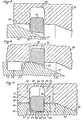
- FIG. 1 shows a seal according to the invention in which a male element 1 is screwed into a female element 2.
- Conical external threads 3 are provided at the end of the male element 1 to cooperate with corresponding conical threads 4 produced on the inner surface of the female element 2.
- These threads are preferably trapezoidal threads which vanish on the outer surface of the male element 1.
- the female element 2 is for example a sleeve comprising at its other end, not shown, another symmetrical thread of the thread 4 to cooperate with one end of another male element and thus form a seal between this other male element and the male element 1.
- the seal according to the invention also comprises an abutment surface 5 at the end of the male element 1 capable of cooperating with an abutment surface 6 of the female element. Sealing is achieved by means of a conical sealing surface 7 of the male element which cooperates with a corresponding conical sealing surface 8 of the female element.
- the male element 1 also has in its cylindrical part between the end of the thread 3 and the sealing surface 7 a circumferential groove 9.
- the female element comprises, in its cylindrical part lying between the end of the thread 4 and the sealing surface 8, a circumferential groove 10.
- the grooves 9 and 10 are opposite as shown in Figure 1.
- the grooves 9 and 10 define an annular space 11 in which is disposed an elastic ring 12.
- the ring elastic is arranged so that it is engaged simultaneously in the grooves 9 and 10.
- Figure 2 shows another seal according to the invention.
- a male element 21 has at its end a two-stage cylindrical external thread 23,23 '.
- the female element 22 has at its end a corresponding cylindrical internal thread with two stages 24, 24 ′.
- the threads 23, 23 'and 24, 24' are for example trapezoidal threads.
- An external abutment surface 25 of the male element also cooperates with a corresponding abutment surface 26 of the female element and the sealing is ensured on the radially inner side by a conical sealing surface 27 of the cooperating male element with a corresponding conical sealing surface 28 of the female element 22.
- a circumferential groove 29 is formed in the cylindrical part of the male element 21 between the end of the thread 23 'and the sealing surface 27.
- a circumferential groove 30 is provided in the female element 22 in its cylindrical part included between the end of the thread 24 'and the sealing surface 28.
- the grooves 29 and 30 are in facing relation and delimit an annular space 31, inside which an elastic ring 32 is arranged, so that it is engaged simultaneously in gorges 29 and 30.
- the elements 21 and 22 can only be unscrewed after shearing of the elastic ring 32.
- the seal shown in FIG. 5 comprises, as before, a male element 41 and a female element 42.
- a circumferential groove 44 In an external cylindrical part 43 of the male element 41 is formed a circumferential groove 44 and in an internal cylindrical part 45 of the female element 42 is formed a circumferential groove 46.
- a conical surface 47 is provided on the male element 41 on the side of the end of this element relative to the groove 44.
- This conical surface can for example be a sealing surface cooperating with a conical surface of corresponding seal 48 provided on the female element 42, but this is not compulsory.
- the grooves 44 and 46 are opposite and delimit an annular space 49 in which the elastic ring 50 is arranged.
- the groove 44 of the male element 41 has two lateral faces 51 and 52 perpendicular to the axis of the joint and a bottom cylindrical surface 53 coaxial with the joint.
- the bottom surface 53 is connected to the lateral faces 51 and 52 by toric surfaces.
- the groove 46 has two lateral faces 54 and 55 which, in the embodiment shown are perpendicular to the axis of the joint, and a cylindrical bottom surface 56 coaxial with the joint.
- the bottom surface 56 is connected to the lateral faces 54 and 55 by toric surfaces.
- the elastic ring 50 is a split ring at a point on its periphery which has two lateral faces 57 and 58 and an outer surface 59 which is a cylindrical surface perpendicular to the lateral faces 57 and 58.
- the internal surface 60 of the ring 50 is a conical surface whose apex is situated on the side of the end of the male element.
- the conical surface 60 is connected on the side of its smallest diameter to the lateral face 58 by a rounding and on the side of its largest diameter to the lateral face 57 by a chamfer 61.
- the groove 46 of the female element 42 has a depth a greater than the radial thickness b of the ring 50 while the groove 44 of the male element 41 has a depth c less than this radial thickness b.
- the split ring 50 has an inside diameter at rest (that is to say when no force directed towards the outside forces it to open), which is less than the diameter of the bottom surface 53 of the groove 44, so that when it is in the position shown in FIG. 5, its conical surface 60 is supported on the surface 53 by its face of smaller diameter.
- the ring 50 is first introduced into the groove 46 of the female element 42 by compressing it radially inwardly to allow it to cross the cylindrical surface 45 and then letting it relax in throat 46.
- the male element 41 is then engaged in the female element 42 in the direction of the arrow 70 by screwing the corresponding threads, shown for example in FIGS. 1 and 2.
- the ring comes to bear on the lateral surface 54 of the groove 46 of the female element and on the lateral face 52 of the groove 44 of the male element.
- the unscrewing torque can be precisely calibrated as a function of the shear strength of the material from which the elastic ring 50 is made and of the axial dimension of the latter.
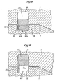
- FIG. 7 represents a seal between a male element 81 and a female element 82 which have cylindrical threads corresponding to two stages 83.83 'and 84.84' respectively.
- No abutment surface is provided in this seal which comprises on the other hand, an internal sealing cone formed by the sealing surface 87 of the male element and the sealing surface 88 of the female element and an external sealing cone formed by the sealing surface 87 " of the male element and the sealing surface 88 'of the female element.
- a groove 44 is formed in the cylindrical part 43 of the male element 81 between the end of the thread 83 'and the conical sealing surface 87.
- a groove 46 is formed in the cylindrical part 45 of the female element between the end of the thread 84 'and the conical sealing surface 88.
- An elastic ring 50 is engaged in the grooves 44 and 46.
- groove 44 ' is formed in the conical sealing surface 87' of the male element 81 and a groove 46 'is formed in the conical sealing surface 88' of the female element 82.
- a second elastic ring 50 ' is arranged in grooves 44' and 46 '.
- this seal is carried out like that of the seals described above except that the two rings 50 and 50 'are arranged in the grooves 46 and 46' of the female element 82 before the introduction of the 'male element 81.
- the radial expansion of the rings is achieved by their contact with the conical sealing surfaces 87 and 87' of the male element.
- the radial expansion of the elastic ring is effected by means of a conical sealing surface of the male element.
- the seal shown in Figure 8 is a variant in which the expansion of the ring is carried out by means of a conical surface specially provided for this purpose which avoids the risk of possible damage to the sealing surfaces of the male element.
- a male element 91 is mounted on a female element 92 by means of complementary threads 93 and 94.
- a groove 44 is formed in a cylindrical surface 43 of the male element and a groove 46 is formed in a surface cylindrical 45 of the female element.
- the male element has an abutment surface 95 capable of cooperating with an abutment surface 96 of the female element, the grooves 44 and 46 being opposite when these surfaces 95 and 96 are in abutment.
- the male element 91 also comprises a conical sealing surface 97 capable of cooperating with a corresponding conical sealing surface 98 of the female element 92.
- the conical sealing surface 97 of the male element is extended by a cylindrical surface 99 then by a second conical surface 100.
- the elastic ring 101 has a minimum internal diameter at rest greater than the diameter of the cylindrical surface 99 of the element male 91.
- FIGS. 9 and 10 show a variant of FIG. 5 according to which the elastic ring 50 is produced with a bimetallic element constituted by a metal 50a disposed inside the ring which has a coefficient of expansion greater than that of the metal 50b which constitutes the external part of the ring 50.
- the bimetallic ring has the same shape as that of Figure 5 and plays the same role by ensuring the same function.
- the joint when the joint is heated to a sufficient temperature, for example from 200 to 300 ° C., the metal 50a expands more than the metal 50b, the ring 50 increases in diameter and is applied spontaneously to the bottom of the groove 46 as seen in FIG. 10. It is thus possible to unscrew the seal without having to shear the ring 50.
- a sufficient temperature for example from 200 to 300 ° C.
- the invention makes it possible, on the one hand, to obtain very large unscrewing torques and, on the other hand, to avoid the drawbacks due to an over-tightening torque. It also makes it possible to ensure precise positioning of the male element in the female element.
- the grooves of the male element and of the female element, while generally being opposite when the seal is mounted, can moreover be slightly offset depending on the operating mode.
- seals described are seals with cylindrical or conical trapezoidal threads, but the invention is capable of being applied to seals of another type.
- the elastic rings are not necessarily placed in the exact locations shown in the drawing.
- the use of elastic rings according to the invention is independent of the presence or absence of stops or screw limiting shoulder.
- sealing surfaces described are conical surfaces, but the invention could obviously be used on seals having cylindrical sealing surfaces.
Abstract
Joint pour tubes, du type dans lequel une extrémité munie d'un filetage, d'un élément mâle (1), est vissée dans un élément femelle (2) présentant un filetage correspondant. L'élément mâle possède à sa surface externe une gorge circonférentielle (9) et l'élément femelle possède à sa surface interne une gorge circonférentielle (10) située en position vissée, en vis-à-vis de la gorge de l'élément mâle, une bague élastique (12) étant prévue pour s'engager simultanément dans lesdites gorges, l'une au moins des gorges ayant une profondeur radiale suffisante pour permettre l'escamotage de la bague lorsque l'élément mâle est engagé dans l'élément femelle.Joint for tubes, of the type in which one end provided with a thread, of a male element (1), is screwed in a female element (2) having a corresponding thread. The male element has on its external surface a circumferential groove (9) and the female element has on its internal surface a circumferential groove (10) located in the screwed position, facing the groove of the male element , an elastic ring (12) being provided to engage simultaneously in said grooves, at least one of the grooves having a radial depth sufficient to allow the retraction of the ring when the male element is engaged in the female element .
Description
La présente invention est relative 'à un joint pour tubes, plus spécialement pour tubes d'acier qui est destiné notamment à l'industrie pétrolière.The present invention relates to a joint for tubes, more particularly for steel tubes which is intended in particular for the petroleum industry.
On connaît des joints utilisés dans l'industrie pétrolière dans lesquels les extrémités de deux éléments mâles sont réunies à l'aide d'un élément femelle, chaque élément mâle étant muni d'un filetage, par exemple tronconique, qui s'engage dans un filetage femelle correspondant pratiqué dans l'élément femelle.Seals used in the petroleum industry are known in which the ends of two male elements are joined using a female element, each male element being provided with a thread, for example frustoconical, which engages in a corresponding female thread made in the female element.
On sait que dans les joints de ce type, les couples de dévissage des éléments mâles sont proportionnels aux couples de serrage. La constante de proportionalité dépend de paramètres tels que le type de graisse utilisée au vissage et l'état de surface des éléments, et a généralement une valeur comprise entre 1 et 1,3.It is known that in joints of this type, the loosening torques of the male elements are proportional to the tightening torques. The proportionality constant depends on parameters such as the type of grease used for screwing and the surface condition of the elements, and generally has a value between 1 and 1.3.
Il est cependant souhaitable pour certaines applications d'augmenter le couple de dévissage du joint et on a déjà proposé à cet effet différentes solutions.It is however desirable for certain applications to increase the torque of unscrewing of the joint and various solutions have already been proposed for this purpose.
La première solution qui est évidente consiste à augmenter le couple de vissage mais cette solution présente des limitations dues à la résistance mécanique du joint, à celle des moyens de serrage ou encore au marquage des éléments par les mors de vissage.The first solution which is obvious consists in increasing the screwing torque but this solution has limitations due to the mechanical resistance of the seal, to that of the clamping means or even to the marking of the elements by the screwing jaws.
Une autre possibilité consiste à utiliser une graisse colle mais cette solution demande des préparations de surface particulières avec des temps de séchage qui dans certains cas sont incompatibles avec les temps de pose. D'autre part, le dévissage de tels joints filetés-collés demande la mise en place de moyens et de méthodes de dévissage particulier.Another possibility is to use an adhesive grease, but this solution requires specific surface preparations with drying times which in some cases are incompatible with the exposure times. On the other hand, the unscrewing of such threaded-glued joints requires the installation of specific unscrewing means and methods.
La présente invention vise à fournir un joint pour tube dans lequel le couple de dévissage est supérieur au couple de dévissage naturel.The present invention aims to provide a joint for a tube in which the unscrewing torque is greater than the natural unscrewing torque.
A cet effet, la présente invention a pour objet un joint pour tube du type dans lequel une extrémité munie d'un filetage d'un élément mâle est vissé dans un élément femelle présentant un filetage correspondant, caractérisé par le fait que l'élément mâle possède à sa surface externe une gorge circonférentielle et que l'élément femelle possède à sa surface interne une gorge circonférentielle située en position vissée, en vis-à-vis de la gorge de l'élément mâle, une bague élastique étant prévue pour s'engager simultanément dans lesdites gorges, l'une au moins des gorges ayant une profondeur radiale suffisante pour permettre l'escamotage de la bague lorsque l'élément mâle est en cours d'engagement dans l'élément femelle.To this end, the subject of the present invention is a joint for tube of the type in which one end provided with a thread of a male element is screwed into a female element having a corresponding thread, characterized in that the male element has on its external surface a circumferential groove and that the female element has on its internal surface a circumferential groove situated in the screwed position, facing the groove of the male element, an elastic ring being provided for simultaneously engage in said grooves, at least one of the grooves having a radial depth sufficient to allow the retraction of the ring when the male element is being engaged in the female element.
Le dévissage ne peut ainsi s'effectuer qu'en cisaillant la bague élastique ce qui permet d'obtenir des couples de dévissage de l'ordre de 1,3 à 20 fois le couple de vissage. On notera que cet agencement permet d'obtenir un couple de dévissage calibré qui ne se substitue pas au couple de dévissage naturel des joints mais qui vient au contraire s'y ajouter.Unscrewing can thus only be carried out by shearing the elastic ring, which makes it possible to obtain unscrewing torques of the order of 1.3 to 20 times the screwing torque. It will be noted that this arrangement makes it possible to obtain a calibrated unscrewing torque which does not replace the natural unscrewing torque of the joints but which, on the contrary, is added thereto.
La bague élastique peut être située soit au voisinage de l'extrémité de l'élément mâle, soit à celui de l'extrémité de l'élément femelle.The elastic ring can be located either near the end of the male element, or near the end of the female element.
On peut également réaliser sur le même joint plusieurs dispositifs de bagues élastiques selon l'invention, notamment en plaçant une bague élastique au voisinage de chaque extrémité du filetage.It is also possible to produce on the same joint several devices of elastic rings according to the invention, in particular by placing an elastic ring in the vicinity of each end of the thread.
On comprend que de tels joints puissent être en particulier utilisés pour des conduites soumises pendant une longue période à des sollicitations par exemple en flexion ou en torsion, ou à des chocs tels que le couple de dévissage naturel puisse être atteint relativement facilement. Ces joints sont en particulier utiles lorsque les conduites soumises à ces sollicitations doivent néanmoins conserver une étanchéité parfaite mais ne sont plus accessibles après leur pose ce qui est en général le cas des conduites sous-marines pour hydrocarbures.It is understood that such seals can in particular be used for pipes subjected for a long period to stresses, for example in bending or in torsion, or to shocks such that the natural unscrewing torque can be reached relatively easily. These joints are particularly useful when the pipes subjected to these stresses must nevertheless maintain a perfect seal but are no longer accessible after their installation, which is generally the case with underwater pipes for hydrocarbons.
Le joint selon l'invention comporte par ailleurs d'autres avantages qui peuvent rendre son utilisation avantageuse dans des cas où l'augmentation du couple de dévissage n'est pas l'objectif principal.The seal according to the invention also has other advantages which can make its use advantageous in cases where increasing the unscrewing torque is not the main objective.
On sait par exemple que pour les joints filetés utilisés dans l'industrie pétrolière il est utile d'avoir un moyen de limitation du couple de serrage pour éviter une déformation permanente du joint en cas de surcouple de serrage. On prévoit souvent à cet effet une butée métallique.We know for example that for threaded joints used in the petroleum industry it is useful to have a means of limiting the tightening torque to avoid permanent deformation of the joint in the event of tightening overtorque. A metal stop is often provided for this purpose.
On conçoit que la bague élastique engagée selon l'invention simultanément dans les gorges de l'élément mâle et de l'élément femelle permet de remplacer avantageusement les butées connues du fait qu'elle travaille également au cisaillement pendant le vissage. De plus, l'agencement selon l'invention peut être utilisé dans des joints possédant une ou plusieurs butées ce qui permet d'assurer une sécurité supplémentaire permettant d'augmenter le couple maximum de vissage du joint.It is understood that the elastic ring engaged according to the invention simultaneously in the grooves of the male element and the female element makes it possible to advantageously replace the known stops because it also works in shearing during screwing. In addition, the arrangement according to the invention can be used in seals having one or more stops, which makes it possible to provide additional security making it possible to increase the maximum screwing torque of the seal.
Dans le cas d'un joint où un élément femelle réunit deux éléments mâles, l'invention permet d'assurer un positionnement bien déterminé d'un des éléments mâles dans l'élément femelle pendant le vissage ou le dévissage de l'autre élément mâle. Si l'invention n'est appliquée que d'un côté du joint, le dévissage est préférentiel et s'effectue toujours de l'autre côté.In the case of a joint where a female element joins two male elements, the invention makes it possible to ensure a well-determined positioning of one of the male elements in the female element during the screwing or unscrewing of the other male element . If the invention is applied only on one side of the joint, unscrewing is preferable and is always carried out on the other side.
Un autre des avantages de l'invention est qu'elle permet d'assurer un positionnement bien déterminé de l'élément mâle dans l'élément femelle après serrage.Another advantage of the invention is that it makes it possible to ensure a well-determined positioning of the male element in the female element after tightening.
Ceci est en particulier nécessaire pour certains joints dans lesquels un élément mâle est monté en usine sur un manchon femelle, un autre élément mâle étant monté sur chantier. Pour que l'élément mâle monté sur chantier puisse se positionner correctement dans l'ensemble monté en usine, il est nécessaire que l'élément mâle monté en usine soit lui-même positionné avec précision.This is in particular necessary for certain seals in which a male element is mounted in the factory on a female sleeve, another male element being mounted on site. In order for the male element mounted on site to be able to position itself correctly in the assembly assembled at the factory, it is necessary that the male element assembled at the factory is itself positioned with precision.
Dans le joint selon l'invention, la bague élastique étant, en position de vissage, engagée simultanément dans une gorge de l'élément mâle et dans une gorge de l'élément femelle, on comprend que la position de l'élément mâle dans l'élément femelle peut être déterminée avec précision puisqu'elle ne dépend que des tolérances d'usinage des gorges.In the seal according to the invention, the elastic ring being, in the screwing position, engaged simultaneously in a groove of the male element and in a groove of the female element, it is understood that the position of the male element in the The female element can be determined with precision since it only depends on the machining tolerances of the grooves.
Dans une forme préférée de l'invention, la gorge de l'élément femelle a une profondeur supérieure à l'épaisseur radiale de la bague élastique.In a preferred form of the invention, the groove of the female element has a depth greater than the radial thickness of the elastic ring.
La mise en place de l'élément mâle dans l'élément femelle peut alors être réalisée en escamotant la bague élastique à l'intérieur de la gorge de l'élément femelle pendant le vissage de l'élément mâle, la bague élastique venant s'enclencher dans la gorge de l'élément mâle en fin de vissage.The positioning of the male element in the female element can then be carried out by retracting the elastic ring inside the groove of the female element during the screwing of the male element, the elastic ring coming from snap into the groove of the male element at the end of screwing.
Cet escamotage de la bague élastique dans la gorge de l'élément femelle est avantageusement réalisé par l'élément mâle lui-même. A cet effet, l'élément mâle possède une surface conique s'amincissant vers l'extrémité de l'élément mâle qui est susceptible de provoquer lors de son introduction dans l'élément femelle l'ouverture de la bague élastique disposée préalablement dans la gorge de l'élément femelle.This retraction of the elastic ring in the groove of the female element is advantageously achieved by the male element itself. To this end, the male element has a conical surface tapering towards the end of the male element which is capable of causing, when it is introduced into the female element, the opening of the elastic ring previously disposed in the groove. of the female element.
Dans une forme de réalisation particulière, cette surface conique de l'élément mâle est une surface d'étanchéité susceptible de coopérer avec une surface complémentaire de l'élément femelle en position de vissage.In a particular embodiment, this conical surface of the male element is a sealing surface capable of cooperating with a complementary surface of the female element in the screwing position.
Cependant, il est possible d'utiliser une surface conique prévue spécialement à cet effet afin d'éviter tout endommagement de la surface d'étanchéité par frottement sur la surface intérieure de la bague élastique.However, it is possible to use a conical surface specially provided for this purpose in order to avoid any damage to the sealing surface by friction on the internal surface of the elastic ring.
Dans une autre forme de réalisation, la surface radialement intérieure de la bague élastique est conique. Sa plus grande ouverture étant disposée dans la gorge de l'élément femelle du côté de l'introduction de l'élément mâle pour coopérer avec une surface de cet élément lors de son introduction et provoquer ainsi l'ouverture de la bague élastique.In another embodiment, the radially inner surface of the elastic ring is conical. Its largest opening being disposed in the groove of the female element on the side of the introduction of the male element to cooperate with a surface of this element during its introduction and thus cause the opening of the elastic ring.
Bien entendu, des surfaces coniques peuvent être prévues à la fois sur l'élément mâle et sur la bague élastique pour permettre une ouverture plus aisée de celle-ci lors de l'introduction de l'élément mâle.Of course, conical surfaces can be provided both on the male element and on the elastic ring to allow easier opening of the latter during the introduction of the male element.
De préférence, la bague élastique a un diamètre intérieur au repos,inférieur au diamètre du fond de la gorge de l'élément mâle et la gorge de l'élément mâle a une profondeur inférieure à l'épaisseur radiale de la bague élastique.Preferably, the elastic ring has an internal diameter at rest, less than the diameter of the bottom of the groove of the male element and the groove of the male element has a depth less than the radial thickness of the elastic ring.
Ainsi la bague élastique est, en utilisation, en appui par sa périphérie radialement intérieure sur le fond de la gorge de l'élément mâle. Cet agencement permet d'assurer le centrage de la bague élastique de sorte que lors du dévissage son cisaillement est effectué sur la totalité de sa périphérie.Thus the elastic ring is, in use, supported by its radially inner periphery on the bottom of the groove of the male element. This arrangement ensures the centering of the elastic ring so that during unscrewing its shearing is carried out over its entire periphery.
La bague élastique est de préférence une bague fendue en un point de sa périphérie mais il va de soi que d'autres formes permettant une expansion radiale de la bague sont possibles.The elastic ring is preferably a split ring at a point on its periphery, but it goes without saying that other shapes allowing radial expansion of the ring are possible.
La bague élastique peut être réalisée dans le même acier que celui du joint mais ceci n'est aucunement nécessaire. La bague élastique peut être réalisée en toute matière et notamment en matière synthétique.The elastic ring can be made of the same steel as that of the seal, but this is not at all necessary. The elastic ring can be made of any material and in particular of synthetic material.
En particulier, dans le cas où l'objectif essentiel du joint selon l'invention est d'obtenir un couple de dévissage élevé, la bague élastique sera réalisée de préférence dans un acier à plus basse limite élastique que celle du matériau dans lequel ont été usinées les gorges pour éviter la détérioration des faces des gorges perpendiculaires à l'axe du joint lors du dévissage.In particular, in the case where the essential purpose of the joint according to the invention is to obtain a high unscrewing torque, the elastic ring will preferably be made of steel with a lower elastic limit than that of the material in which the grooves have been machined to avoid deterioration of the faces of the grooves perpendicular to the joint axis when unscrewing.
Dans d'autres applications de l'invention comme celle où l'objectif essentiel est d'obtenir un positionnement rigoureux de l'élément mâle par rapport à l'élément femelle, on pourra utiliser un acier à limite élastique plus élevée que celle du matériau dans lequel ont été usinées les gorges par exemple un acier à ressort.In other applications of the invention such as that where the essential objective is to obtain a rigorous positioning of the male element relative to the female element, it is possible to use a steel with elastic limit higher than that of the material. in which the grooves have been machined, for example a spring steel.
Dans un mode de réalisation particulier de l'invention, la bague élastique est constituée par un élément bimétallique circulaire qui, à la température ambiante, se comporte comme une bague du type préalablement décrit, mais qui, par élévation de température, peut se déformer spontanément de manière à s'appliquer au fond de la gorge qui contient entièrement la bague lors de l'engagement de l'autre élément.In a particular embodiment of the invention, the elastic ring is constituted by a circular bimetallic element which, at ambient temperature, behaves like a ring of the type previously described, but which, by raising of temperature, can deform spontaneously so as to apply to the bottom of the groove which entirely contains the ring when the other element is engaged.
On peut ainsi avoir un joint qui présente à l'état vissé toutes les qualités décrites ci-dessus et qui peut être dévissé soit en cisaillant la bague qui se comporte comme une bague normale, soit en portant le joint avant son dévissage à une température suffisante pour que, par l'effet de bilame, la bague vienne s'appliquer au fond de la gorge qui peut la contenir toute entière ce qui permet d'effectuer le dévissage du joint avec un couple qui correspond aux seuls frottements.It is thus possible to have a seal which has in the screwed state all the qualities described above and which can be unscrewed either by shearing the ring which behaves like a normal ring, or by bringing the seal before its unscrewing to a sufficient temperature. so that, by the effect of bimetallic strip, the ring comes to apply to the bottom of the groove which can contain it entirely, which makes it possible to unscrew the joint with a torque which corresponds to friction only.
On va maintenant décrire à titre d'exemple non limitatif plusieurs modes de réalisation de l'invention qui sont représentés schématiquement sur le dessin annexé dans lequel :
- - La figure 1 est une vue en coupe axiale d'un premier mode de réalisation d'un joint selon l'invention,
- - La figure 2 est une vue en coupe axiale d'un joint selon un second mode de réalisation de l'invention,
- - La figure 3 est une vue en coupe à une plus grande échelle représentant dans un joint selon l'invention une étape de l'introduction d'un élément mâle dans un élément femelle muni d'une bague élastique,
- - La figure 4 est une vue similaire à la figure 3 réprésentant une étape ultérieure,
- - La figure 5 est une vue similaire aux figures 3 et 4 représentant le joint après vissage complet de l'élément mâle dans l'élément femelle,
- - La figure 6 est une vue en coupe axiale d'un joint selon l'invention représentant une première application de celle-ci, (augmentation du couple de dévissage),
- - La figure 7 est une vue similaire à la figure 6 représentant une autre application de l'invention, (positionnement des éléments et augmentation de couples de vissage et de dévissage) et
- - La figure 8 est une vue en coupe à plus grande échelle d'un joint selon une variante de l'invention,
- - La figure 9 est une variante de la figure 5 comportant un joint bimétallique,
- - et la figure 10 représente le joint bimétallique de la position de dévissage après réchauffage du joint.
- - Figure 1 is an axial sectional view of a first mode of production of a seal according to the invention,
- FIG. 2 is a view in axial section of a seal according to a second embodiment of the invention,
- FIG. 3 is a sectional view on a larger scale showing in a joint according to the invention a step of introducing a male element into a female element provided with an elastic ring,
- FIG. 4 is a view similar to FIG. 3 showing a subsequent step,
- FIG. 5 is a view similar to FIGS. 3 and 4 showing the joint after complete screwing of the male element into the female element,
- FIG. 6 is a view in axial section of a seal according to the invention representing a first application thereof, (increase in the unscrewing torque),
- FIG. 7 is a view similar to FIG. 6 showing another application of the invention, (positioning of the elements and increase of screwing and unscrewing torques) and
- FIG. 8 is a sectional view on a larger scale of a seal according to a variant of the invention,
- FIG. 9 is a variant of FIG. 5 comprising a bimetallic seal,
- - And Figure 10 shows the bimetallic seal of the unscrewing position after reheating the seal.
Pour une meilleure lisibilité de ces figures, les proportions n'ont généralement pas été respectées. Il en est ainsi en particulier en ce qui concerne les jeux entre les bagues élastiques et les gorges qui les reçoivent.For better readability of these figures, the proportions have generally not been met. This is particularly so with regard to the clearances between the elastic rings and the grooves which receive them.
La figure 1 représente un joint selon l'invention dans lequel un élément mâle 1 est vissé dans un élément femelle 2. Des filetages extérieurs coniques 3 sont prévus à l'extrémité de l'élément mâle 1 pour coopérer avec des filetages coniques correspondants 4 réalisés à la surface intérieure de l'élément femelle 2. Ces filetages sont de préférence des filetages trapézoïdaux s'évanouissant à la surface extérieure de l'élément mâle 1.FIG. 1 shows a seal according to the invention in which a male element 1 is screwed into a
L'élément femelle 2 est par exemple un manchon comportant à son autre extrémité, non représentée, un autre filetage symétrique du filetage 4 pour coopérer avec une extrémité d'un autre élément mâle et former ainsi un joint entre cet autre élément mâle et l'élément mâle 1.The
Le joint selon l'invention comporte par ailleurs une surface de butée 5 à l'extrémité de l'élément mâle 1 susceptible de coopérer avec une surface de butée 6 de l'élément femelle. L'étanchéité est réalisée au moyen d'une surface conique d'étanchéité 7 de l'élément mâle qui coopère avec une surface conique d'étanchéité correspondante 8 de l'élément femelle.The seal according to the invention also comprises an
L'élément mâle 1 comporte par ailleurs dans sa partie cylindrique comprise entre l'extrémité du filetage 3 et la surface d'étanchéité 7 une gorge circonférentielle 9.The male element 1 also has in its cylindrical part between the end of the
De même, l'élément femelle comporte dans sa partie cylindrique comprise entre l'extrémité du filetage 4 et la surface d'étanchéité 8, une gorge circonférentielle 10.Likewise, the female element comprises, in its cylindrical part lying between the end of the thread 4 and the sealing
Lorsque l'élément mâle 1 est complétement vissé dans l'élément femelle 2, c'est-à-dire lorsque les surfaces de butée 5 et 6 sont en contact, les gorges 9 et 10 sont en vis-à-vis comme cela est représenté à la figure 1. Dans cette position, les gorges 9 et 10 définissent un espace annulaire 11 dans lequel est disposée une bague élastique 12. La bague élastique est agencée de telle sorte qu'elle soit engagée simultanément dans les gorges 9 et 10.When the male element 1 is completely screwed into the
On décrira ci-après plus en détail la façon dont la bague élastique 12 est disposée dans l'espace annulaire 11 en référence aux'figures 3 à 5. Néanmoins, on peut comprendre dès à présent qu'une fois dans la position représentée à la figure 1, le joint selon l'invention ne peut être démonté par dévissage de l'élément mâle 1 qu'après cisaillement de la bague élastique 12.The manner in which the
La figure 2 représente un autre joint selon l'invention.Figure 2 shows another seal according to the invention.
Dans ce joint un élément mâle 21 comporte à son extrémité un filetage extérieur cylindrique à deux étages 23,23'. De même, l'élément femelle 22 comporte à son extrémité un filetage intérieur correspondant cylindrique à deux étages 24,24'. Les filetages 23,23' et 24,24' sont par exemple des filetages trapézoïdaux.In this joint a
Une surface de butée externe 25 de l'élément mâle coopère par ailleurs avec une surface de butée correspondante 26 de l'élément femelle et l'étanchéité est assurée du côté radialement intérieur par une surface conique d'étanchéité 27 de l'élément mâle coopérant avec une surface correspondante conique d'étanchéité 28 de l'élément femelle 22.An
Comme dans le cas précédent une gorge circonférentielle 29 est formée dans la partie cylindrique de l'élément mâle 21 comprise entre l'extrémité du filetage 23' et la surface d'étanchéité 27. De même, une gorge circonférentielle 30 est prévue dans l'élément femelle 22 dans sa partie cylindrique comprise entre l'extrémité du filetage 24' et la surface d'étanchéité 28.As in the previous case a
Lorsque les surfaces 25 et 26 sont en butée, les gorges 29 et 30 sont en vis-à-vis et délimitent un espace annulaire 31, à l'intérieur duquel est disposée une bague élastique 32, de telle sorte qu'elle soit engagée simultanément dans les gorges 29 et 30.When the
Comme dans le cas précédent, les éléments 21 et 22 ne peuvent être dévissés qu'après cisaillement de la bague élastique 32.As in the previous case, the
On décrira maintenant plus en détail en référence à la figure 5, la bague élastique du joint selon l'invention ainsi que les parties des éléments mâles et femelles dans lesquels sont ménagées les gorges circonférentielles.Will now be described in more detail with reference to Figure 5, the elastic ring of the seal according to the invention and the parts of the male and female elements in which are formed the circumferential grooves.
Le joint représenté à la figure 5 comporte comme précédemment un élément mâle 41 et un élément femelle 42. Dans une partie cylindrique extérieure 43 de l'élément mâle 41 est formée une gorge circonférentielle 44 et dans une partie cylindrique intérieure 45 de l'élément femelle 42 est formée une gorge circonférentielle 46.The seal shown in FIG. 5 comprises, as before, a
Par ailleurs, une surface conique 47 est prévue sur l'élément mâle 41 du côté de l'extrémité de cet élément par rapport à la gorge 44. Cette surface conique peut par exemple être une surface d'étanchéité coopérant avec une surface conique d'étanchéité correspondante 48 prévue sur l'élément femelle 42, mais cela n'est pas obligatoire.Furthermore, a
Dans la position assemblée du joint, comme par exemple dans la position représentée aux figures 1 et 2, les gorges 44 et 46 se trouvent en vis-à-vis et délimitent un espace annulaire 49 dans lequel est disposée la bague élastique 50.In the assembled position of the seal, as for example in the position represented in FIGS. 1 and 2, the
La gorge 44 de l'élément mâle 41 comporte deux faces latérales 51 et 52 perpendiculaires à l'axe du joint et une surface cylindrique de fond 53 coaxiale au joint. Dans le mode de réalisation décrit, la surface de fond 53 est reliée aux faces latérales 51 et 52 par des surfaces toriques.The
De même, la gorge 46 comporte deux faces latérales 54 et 55 qui, dans le mode de réalisation représenté sont perpendiculaires à l'axe du joint, et une surface de fond cylindrique 56 coaxiale au joint. La surface de fond 56 est reliée aux faces latérales 54 et 55 par des surfaces toriques.Similarly, the
La bague élastique 50 est une bague fendue en un point de sa périphérie qui comporte deux faces latérales 57 et 58 et une surface extérieure 59 qui est une surface cylindrique perpendiculaire aux faces latérales 57 et 58.The
Par contre, la surface intérieure 60 de la bague 50 est une surface conique dont le sommet est situé du côté de 1"extrémité de l'élément mâle. La surface conique 60 est reliée du côté de son plus petit diamètre à la face latérale 58 par un arrondi et du côté de son plus grand diamètre à la face latérale 57 par un chanfrein 61.On the other hand, the
Par ailleurs, la gorge 46 de l'élément femelle 42 a une profondeur a supérieure à l'épaisseur radiale b de la bague 50 alors que la gorge 44 de l'élément mâle 41 a une profondeur c inférieure à cette épaisseur radiale b.Furthermore, the
Enfin, la bague fendue 50 a un diamètre intérieur au repos, (c'est-à-dire lorsqu'aucun effort dirigé vers l'extérieur ne la contraint à s'ouvrir), qui est inférieur au diamètre de la surface de fond 53 de la gorge 44, de sorte que lorsqu'elle est dans la position représentée à la figure 5, sa surface conique 60 est en appui sur la surface 53 par sa face de plus faible diamètre.Finally, the
Le montage des joints décrit ci-dessus s'effectue de la façon représentée aux figures 3 et 4.The assembly of the seals described above is carried out as shown in Figures 3 and 4.
Comme montré à la figure 3, la bague 50 est tout d'abord introduite dans la gorge 46 de l'élément femelle 42 en la comprimant radialement vers l'intérieur pour lui permettre de franchir la surface cylindrique 45 puis en la laissant se détendre dans la gorge 46.As shown in Figure 3, the
L'élément mâle 41 est alors engagé dans l'élément femelle 42 dans le sens de la flèche 70 par vissage des filetages correspondants, représentés par exemple aux figures 1 et 2.The
Lorsque la surface conique 47 de l'élément mâle 41 vient au contact de l'arête de la bague 50 formée entre sa surface intérieure 60 et le chanfrein 61, elle provoque le centrage de la bague 50 sur l'axe du joint puis son expansion radiale.When the
Cette expansion se poursuit jusque dans la position représentée à la figure 4 où elle est alors provoquée par le contact de la surface conique 60 de la bague 50 avec l'arête de l'élément mâle 41 formée entre sa partie cylindrique 43 et sa partie conique 47. Cette expansion cesse lorsque cette arête vient au niveau de la partie de plus petit diamètre de la surface conique 60. Au cours de l'avance ultérieure de l'élément mâle 41 dans l'élément femelle 42 dans le sens de la flèche 70, cette partie de plus faible diamètre de la surface 60 se déplace le long de la surface 43 jusqu'à ce que la gorge 44 de l'élément mâle arrive en vis-à-vis de la gorge 46 de l'élément femelle 42. Ayant été précédemment expansée élastiquement,la bague 50 se contracte alors radialement en s'engageant dans la gorge 44 pour venir dans la position représentée à la figure 5.This expansion continues until in the position shown in Figure 4 where it is then caused by the contact of the
Le démontage du joint selon l'invention s'effectue de la manière représentée à la figure 6 qui représente une partie d'un joint du type de celui de la figure 2..The disassembly of the seal according to the invention is carried out as shown in Figure 6 which shows a part a joint of the type of that of FIG. 2 ..
Pour commencer à faire tourner l'élément mâle 71 par rapport à l'élément femelle 72, il faut tout d'abord atteindre le couple de dévissage naturel qui est généralement compris entre 1 fois et 1,3 fois le couple de vissage.To start rotating the
Après une très faible rotation correspondant à un déplacement axial des éléments l'un par rapport à l'autre de l'ordre du jeu axial de la bague 50 dans les gorges 44 et 46, la bague vient en appui sur la surface latérale 54 de la gorge 46 de l'élément femelle et sur la face latérale 52 de la gorge 44 de l'élément mâle.After a very small rotation corresponding to an axial displacement of the elements relative to each other of the order of the axial clearance of the
En augmentant alors le couple de dévissage, on provoque tout d'abord un écrasement puis un cisaillement de la bague engendrant sa rupture et rendant possible le dévissage complet du joint.By then increasing the unscrewing torque, it first causes a crushing then a shearing of the ring causing its rupture and making possible the complete unscrewing of the joint.
Bien entendu le frettage des cônes d'étanchéité 47 et.48 sera calculé de telle sorte que dans la position représentée à la figure 6 où le couple de dévissage augmente brutalement, l'étanchéité soit encore assurée.Of course, the hooping of the sealing
Par ailleurs, le couple de dévissage peut être calibré avec précision en fonction de la résistance au cisaillement du matériau dans lequel est réalisé la bague élastique 50 et de la dimension axiale de celle-ci.Furthermore, the unscrewing torque can be precisely calibrated as a function of the shear strength of the material from which the
Une autre application du joint selon l'invention est illustrée à la figure 7 qui représente un joint entre un élément mâle 81 et un élément femelle 82 qui comportent des filetages cylindriques correspondant à deux étages 83,83' et respectivement 84,84'.Another application of the seal according to the invention is illustrated in FIG. 7 which represents a seal between a
Aucune surface de butée n'est prévue dans ce joint qui comporte par contre un cône d'étanchéité intérieur formé par la surface d'étanchéité 87 de l'élément mâle et la surface d'étanchéité 88 de l'élément femelle et un cône d'étanchéité extérieur formé par la surface d'étanchéité 87"de l'élément mâle et la surface d'étanchéité 88' de l'élément femelle.No abutment surface is provided in this seal which comprises on the other hand, an internal sealing cone formed by the sealing
Comme précédemment, une gorge 44 est formée dans la partie cylindrique 43 de l'élément mâle 81 comprise entre l'extrémité du filetage 83' et la surface conique d'étanchéité 87. De même, une gorge 46 est formée dans la partie cylindrique 45 de l'élément femelle comprise entre l'extrémité du filetage 84' et la surface conique d'étanchéité 88. Une bague élastique 50 est engagée dans les gorges 44 et 46.As before, a
De plus, une autre gorge 44' est formée dans la surface d'étanchéité conique 87' de l'élément mâle 81 et une gorge 46' est formée dans la surface d'étanchéité conique 88' de l'élément femelle 82. Une deuxième bague élastique 50' est disposée dans les gorges 44' et 46'.In addition, another groove 44 'is formed in the conical sealing surface 87' of the
Le montage de ce joint s'effectue comme celui des joints décrits ci-dessus si ce n'est que les deux bagues 50 et 50' sont disposées dans les gorges 46 et 46' de l'élément femelle 82 avant l'introduction de l'élément mâle 81. L'expansion radiale des bagues est réalisée par leur contact avec les surfaces coniques d'étanchéité 87 et 87' de l'élément mâle.The mounting of this seal is carried out like that of the seals described above except that the two
Un joint de ce type ne comportant pas de butée,un couple de serrage excessif pourrait conduire à une déformation permanente de l'élément femelle 82 dans les zones de ses surfaces d'étanchéité 88 et 88'. Cet inconvénient est supprimé par les bagues selon l'invention. En effet, une fois les bagues 50 et 50' engagées dans les gorges 44 et 44' de l'élément mâle 81, une très faible rotation amène la bague 50 à venir en contact avec la face latérale 58 de la gorge 46 de l'élément femelle et avec la face latérale 51 de la gorge 44 de l'élément mâle. De même, la bague 50' vient en contact avec la face latérale 58' de la gorge 46' de l'élément femelle et avec la face latérale 51' de la gorge 44' de l'élément mâle.Since a seal of this type does not have a stop, excessive tightening torque could lead to permanent deformation of the female element 82 in the regions of its sealing surfaces 88 and 88 '. This drawback is eliminated by the rings according to the invention. Indeed, once the
Dans cette position, qui est celle représentée à la figure 7, le couple de vissage augmente brutalement puisque le vissage ne pourrait être poursuivi que par écrasement et le cisaillement des bagues 50 et 50'. On comprend par conséquent que cet agencement protège le joint vis-à-vis des déformations permanentes qui pourraient résulter d'un couple de vissage excessif.In this position, which is that shown in FIG. 7, the screwing torque increases suddenly since the screwing could only be continued by crushing and shearing of the
Bien entendu, le démontage du joint représenté à la figure 7 s'effectue comme celui des joints décrits ci-dessus, c'est-à-dire par cisaillement des bagues élastiques 50 et 50'.Of course, the disassembly of the seal shown in FIG. 7 is carried out like that of the seals described above, that is to say by shearing of the
Dans tous les joints décrits ci-dessus, l'expansion radiale de la bague élastique s'effectue au moyen d'une surface d'étanchéité conique de l'élément mâle.In all the joints described above, the radial expansion of the elastic ring is effected by means of a conical sealing surface of the male element.
Le joint représenté à la figure 8 est une variante dans laquelle l'expansion de la bague est réalisée au moyen d'une surface conique prévue spécialement à cet effet ce qui permet d'éviter le risque d'un endommagement éventuel des surfaces d'étanchéité de l'élément mâle.The seal shown in Figure 8 is a variant in which the expansion of the ring is carried out by means of a conical surface specially provided for this purpose which avoids the risk of possible damage to the sealing surfaces of the male element.
Dans cette variante, un élément mâle 91 est monté sur un élément femelle 92 au moyen de filetages complémentaires 93 et 94. Comme précédemment une gorge 44 est formée dans une surface cylindrique 43 de l'élément mâle et une gorge 46 est formée dans une surface cylindrique 45 de l'élément femelle. L'élément mâle comporte une surface de butée 95 susceptible de coopérer avec une surface de butée 96 de l'élément femelle, les gorges 44 et 46 se trouvant en vis-à-vis lorsque ces surfaces 95 et 96 sont en butée.In this variant, a
L'élément mâle 91 comporte par ailleurs une surface conique d'étanchéité 97 susceptible de coopérer avec une -surface conique d'étanchéité correspondante 98 de l'élément femelle 92.The
La surface conique d'étanchéité 97 de l'élément mâle est prolongée par une surface cylindrique 99 puis par une deuxième surface conique 100. La bague élastique 101 a un diamètre intérieur minimum au repos supérieur au diamètre de la surface cylindrique 99 de l'élément mâle 91.The
Ainsi, lorsque l'élément mâle 91 est engagé dans l'élément femelle 92, sa surface d'étanchéité 97 franchit la bague 101 sans venir à son contact et elle ne peut ainsi être endommagée. L'expansion de la bague 101 est ensuite effectuée au moyen de la surface conique 100 comme cela a été décrit précédemment.Thus, when the
On a représenté sur les figures 9 et 10 une variante de la figure 5 selon laquelle la bague élastique 50 est réalisée avec un élément bilame constitué par un métal 50a disposé à l'intérieur de la bague qui possède un coefficient de dilatation supérieur à celui du métal 50b qui constitue la partie externe de la bague 50.FIGS. 9 and 10 show a variant of FIG. 5 according to which the
Comme on le voit sur la figure 9, la bague bimétallique a la même forme que celle de la figure 5 et joue le même rôle en assurant la même fonction.As seen in Figure 9, the bimetallic ring has the same shape as that of Figure 5 and plays the same role by ensuring the same function.
Par contre, lorsque l'on chauffe le joint à une température suffisante, par exemple de 200 à 300°C, le métal 50a se dilatant plus que le métal 50b, la bague 50 augmente de diamètre et vient s'appliquer spontanément au fond de la gorge 46 comme on le voit sur la figure 10. On peut ainsi dévisser le joint sans avoir à cisailler la bague 50.On the other hand, when the joint is heated to a sufficient temperature, for example from 200 to 300 ° C., the
On comprend que si, lors du dévissage, la bague devait venir s'appliquer au fond de la gorge pratiquée dans l'élément mâle le métal qui a le plus grand coefficient de dilatation devait se trouver à l'extérieur de la bague 50.It will be understood that if, during unscrewing, the ring had to come to apply to the bottom of the groove formed in the male element, the metal which has the greatest coefficient of expansion had to be outside the
On constate par conséquent que l'invention permet d'une part d'obtenir des couples de dévissage très importants et d'autre part d'éviter les inconvénients dus à un surcouple de vissage. Elle permet par ailleurs d'assurer un positionnement précis de l'élément mâle dans l'élément femelle. Les gorges de l'élément mâle et de l'élément femelle, tout en étant généralement en vis-à-vis lorsque le joint est monté peuvent d'ailleurs être légèrement décalées suivant le mode de fonctionnement.It can therefore be seen that the invention makes it possible, on the one hand, to obtain very large unscrewing torques and, on the other hand, to avoid the drawbacks due to an over-tightening torque. It also makes it possible to ensure precise positioning of the male element in the female element. The grooves of the male element and of the female element, while generally being opposite when the seal is mounted, can moreover be slightly offset depending on the operating mode.
Bien entendu, la forme en coupe axiale des gorges et de la bague qui a été décrite en détail en référence à la figure 5 n'est aucunement limitative. Toute autre forme rendant possible l'expansion radiale de la bague rentre dans le cadre de l'invention.Of course, the shape in axial section of the grooves and of the ring which has been described in detail with reference to FIG. 5 is in no way limiting. Any other shape making possible the radial expansion of the ring falls within the scope of the invention.
De même, les joints décrits sont des joints à filetages trapézoïdaux cylindriques ou coniques, mais l'invention est susceptible de s'appliquer à des joints d'un autre type.Likewise, the seals described are seals with cylindrical or conical trapezoidal threads, but the invention is capable of being applied to seals of another type.
Il va de soi que les bagues élastiques ne sont pas obligatoirement placées aux endroits exacts représentés sur le dessin. En particulier, on peut utiliser une bague élastique située au voisinage de l'extrémité de l'élément femelle comme par exemple la bague 58' de la figure 7. De même, l'utilisation de bagues élastiques selon l'invention est indépendante de la présence ou non de butées ou d'épaulement de limitation de vissage.It goes without saying that the elastic rings are not necessarily placed in the exact locations shown in the drawing. In particular, it is possible to use an elastic ring located in the vicinity of the end of the female element such as, for example, the
En outre, toutes les surfaces d'étanchéité décrites sont des surfaces coniques, mais l'invention pourrait évidemment être utilisée sur des joints possédant des surfaces d'étanchéité cylindriques.In addition, all the sealing surfaces described are conical surfaces, but the invention could obviously be used on seals having cylindrical sealing surfaces.
Enfin, ce qui a été dit concernant les éléments mâles et femelles pourrait être inversé, la bague élastique étant tout d'abord mise en place dans la gorge de l'élément mâle et étant, lors du vissage, escamotée dans cette gorge par une surface de l'élément femelle.Finally, what has been said concerning the male and female elements could be reversed, the elastic ring being first of all placed in the groove of the male element and being, during the screwing, retracted into this groove by a surface of the female element.
Claims (8)
Priority Applications (1)
| Application Number | Priority Date | Filing Date | Title |
|---|---|---|---|
| AT81401132T ATE11688T1 (en) | 1980-07-17 | 1981-07-16 | CONNECTION FOR PIPES, PARTICULARLY FOR USE IN THE PETROLEUM INDUSTRY. |
Applications Claiming Priority (2)
| Application Number | Priority Date | Filing Date | Title |
|---|---|---|---|
| FR8015829 | 1980-07-17 | ||
| FR8015829A FR2487037B1 (en) | 1980-07-17 | 1980-07-17 | JOINT FOR TUBES INTENDED IN PARTICULAR FOR THE OIL INDUSTRY |
Publications (3)
| Publication Number | Publication Date |
|---|---|
| EP0044778A2 true EP0044778A2 (en) | 1982-01-27 |
| EP0044778A3 EP0044778A3 (en) | 1982-02-24 |
| EP0044778B1 EP0044778B1 (en) | 1985-02-06 |
Family
ID=9244252
Family Applications (1)
| Application Number | Title | Priority Date | Filing Date |
|---|---|---|---|
| EP81401132A Expired EP0044778B1 (en) | 1980-07-17 | 1981-07-16 | Joint for pipes intended in particular for the petroleum industry |
Country Status (18)
| Country | Link |
|---|---|
| US (1) | US4426105A (en) |
| EP (1) | EP0044778B1 (en) |
| JP (1) | JPS5944551B2 (en) |
| AR (1) | AR228366A1 (en) |
| AT (1) | ATE11688T1 (en) |
| AU (1) | AU547194B2 (en) |
| BR (1) | BR8104571A (en) |
| CA (1) | CA1164499A (en) |
| DE (3) | DE3128008C2 (en) |
| DK (1) | DK317881A (en) |
| EG (1) | EG15014A (en) |
| ES (1) | ES268532Y (en) |
| FR (1) | FR2487037B1 (en) |
| GB (1) | GB2080468B (en) |
| IT (1) | IT1138089B (en) |
| MX (1) | MX151796A (en) |
| NO (1) | NO812454L (en) |
| OA (1) | OA06859A (en) |
Cited By (5)
| Publication number | Priority date | Publication date | Assignee | Title |
|---|---|---|---|---|
| EP0173691A1 (en) * | 1984-02-24 | 1986-03-12 | George M Raulins | Pipe joint. |
| GB2258709A (en) * | 1991-08-15 | 1993-02-17 | Geolink | Pin and box connection |
| US5527330A (en) * | 1994-08-18 | 1996-06-18 | United States Surgical Corporation | Fluid cutting instrument |
| WO1997026437A1 (en) * | 1996-01-20 | 1997-07-24 | Boart Longyear Limited | Threaded joint |
| FR2791755A1 (en) * | 1999-04-02 | 2000-10-06 | Air Liquide | Connector for attachment of pipes under pressure e.g. carrying gas, has inlet opening and ring groove with circlip, plug and coupling parts |
Families Citing this family (71)
| Publication number | Priority date | Publication date | Assignee | Title |
|---|---|---|---|---|
| EP0127560B1 (en) * | 1983-04-29 | 1990-01-03 | Baker Hughes Incorporated | Threaded coupling comprising a ventable seal |
| GB2156933B (en) * | 1984-02-21 | 1988-01-13 | Vetco Offshore Ind Inc | Pipe connector |
| DE3413792C1 (en) * | 1984-04-12 | 1985-11-28 | Rheinische Braunkohlenwerke AG, 5000 Köln | Connection for pipes which can be screwed to one another |
| GB8414203D0 (en) * | 1984-06-04 | 1984-07-11 | Hunting Oilfield Services Ltd | Pipe connectors |
| US4733890A (en) * | 1984-07-09 | 1988-03-29 | Stratoflex, Inc. | Formed fluid coupling apparatus |
| US4611837A (en) * | 1984-07-23 | 1986-09-16 | Grumann Aerospace Corporation | Tubular element coupling means |
| US4616856A (en) * | 1985-04-25 | 1986-10-14 | S&C Electric Company | Nozzle and retaining arrangement |
| US4629225A (en) * | 1985-08-09 | 1986-12-16 | Inco Alloys International, Inc. | Pipe joint for corrosion resistant alloys |
| GB8617827D0 (en) * | 1986-07-22 | 1986-08-28 | British Steel Corp | Joints for tubular members |
| US4796928A (en) * | 1987-09-28 | 1989-01-10 | Baker Hughes Incorporated | Threaded connection for pipes and method of fabricating same |
| US4836306A (en) * | 1987-12-14 | 1989-06-06 | Ingersoll-Rand Company | Down hole drill chuck lock |
| US5080521A (en) * | 1988-03-30 | 1992-01-14 | Aeroquip Corporation | "O" ring locking mechanism |
| US5126927A (en) * | 1988-03-31 | 1992-06-30 | The Brinkmann Corporation | Flashlight having improved bulb enclosure |
| CA2085556A1 (en) * | 1991-12-18 | 1993-06-19 | Marc J. Smet | Quick connect pipe coupling |
| US5251942A (en) * | 1992-03-05 | 1993-10-12 | Whaley Kent R | Self-sealing pipe thread |
| US5845945A (en) * | 1993-10-07 | 1998-12-08 | Carstensen; Kenneth J. | Tubing interconnection system with different size snap ring grooves |
| CA2219893A1 (en) * | 1993-12-17 | 1996-11-07 | Sandvik Ab | Threaded coupling, male and female extension members as well as a method of maintaining a threaded coupling |
| DE4437952C2 (en) * | 1994-10-24 | 2003-05-28 | Hilti Ag | drilling |
| EP0824627B1 (en) * | 1995-05-04 | 2003-09-10 | Sandvik Aktiebolag | Threaded coupling, male and female extension members as well as a method of maintaining a threaded coupling |
| US5968370A (en) * | 1998-01-14 | 1999-10-19 | Prowler Environmental Technology, Inc. | Method of removing hydrocarbons from contaminated sludge |
| GB2351309B (en) * | 1998-02-18 | 2002-12-04 | Camco Int | A method of setting a well lock |
| US6022366A (en) * | 1998-06-11 | 2000-02-08 | Stat Medical Devices Inc. | Lancet having adjustable penetration depth |
| US7175641B1 (en) | 1998-06-11 | 2007-02-13 | Stat Medical Devices, Inc. | Lancet having adjustable penetration depth |
| US6346114B1 (en) | 1998-06-11 | 2002-02-12 | Stat Medical Devices, Inc. | Adjustable length member such as a cap of a lancet device for adjusting penetration depth |
| US6283511B1 (en) | 1998-08-24 | 2001-09-04 | Well Engineering Partners, B.V. | Pipe coupling |
| US6283982B1 (en) * | 1999-10-19 | 2001-09-04 | Facet Technologies, Inc. | Lancing device and method of sample collection |
| US8814896B2 (en) | 1999-11-02 | 2014-08-26 | Stat Medical Devices, Inc. | Single use lancet assembly |
| US20050070945A1 (en) | 1999-11-02 | 2005-03-31 | Steven Schraga | Single use lancet assembly |
| US6530937B1 (en) | 2000-01-28 | 2003-03-11 | Stat Medical Devices, Inc. | Adjustable tip for a lancet device and method |
| US7344546B2 (en) * | 2000-04-05 | 2008-03-18 | Pathway Medical Technologies | Intralumenal material removal using a cutting device for differential cutting |
| US6908121B2 (en) * | 2001-10-22 | 2005-06-21 | Weatherford/Lamb, Inc. | Locking arrangement for a threaded connector |
| US6666480B2 (en) * | 2001-11-20 | 2003-12-23 | Modern Products Industries, Inc. | Submersible pump drop pipe and casing assembly connection and method of manufacture |
| US20030184084A1 (en) * | 2002-04-01 | 2003-10-02 | Winship Thomas E. | Replaceable corrosion resistant tool joint seal |
| US8715309B2 (en) | 2002-04-29 | 2014-05-06 | Steven Schraga | Lancet device |
| US7086669B2 (en) * | 2002-11-07 | 2006-08-08 | Grant Prideco, L.P. | Method and apparatus for sealing radially expanded joints |
| US20070228729A1 (en) * | 2003-03-06 | 2007-10-04 | Grimmett Harold M | Tubular goods with threaded integral joint connections |
| US20060006648A1 (en) * | 2003-03-06 | 2006-01-12 | Grimmett Harold M | Tubular goods with threaded integral joint connections |
| US7621931B2 (en) * | 2003-05-20 | 2009-11-24 | Stat Medical Devices, Inc. | Adjustable lancet device and method |
| US7905898B2 (en) * | 2003-08-15 | 2011-03-15 | Stat Medical Devices, Inc. | Adjustable lancet device and method |
| US7105006B2 (en) | 2003-08-15 | 2006-09-12 | Stat Medical Devices, Inc. | Adjustable lancet device and method |
| US8257380B2 (en) * | 2004-06-29 | 2012-09-04 | Stat Medical Devices, Inc. | Adjustabable disposable/single-use lancet device and method |
| US8105347B2 (en) * | 2004-11-16 | 2012-01-31 | Stat Medical Devices, Inc. | Adjustable disposable/single-use blade lancet device and method |
| US8066728B2 (en) * | 2004-11-30 | 2011-11-29 | Stat Medical Devices, Inc. | Disposable or single-use lancet device and method |
| US9289161B2 (en) * | 2005-01-28 | 2016-03-22 | Stat Medical Divices, Inc. | Multi-lancet unit, method and lancet device using the multi-lancet unit, and method of assembling and/or making the multi-lancet unit |
| ZA200711031B (en) | 2005-06-27 | 2009-03-25 | Au Parker Hannifin Pty Ltd | A fluid coupling |
| US7434850B2 (en) * | 2005-09-30 | 2008-10-14 | Prinsco, Inc. | Fluid-tight coupling system for corrugated pipe |
| US7704265B2 (en) | 2005-11-03 | 2010-04-27 | Stat Medical Devices, Inc. | Disposable/single-use blade lancet device and method |
| US20080092241A1 (en) * | 2006-10-11 | 2008-04-17 | Media Machines, Inc. | Provision and use of digital rights data for embedded content over networked systems |
| US8043318B2 (en) | 2007-02-08 | 2011-10-25 | Stat Medical Devices, Inc. | Push-button lance device and method |
| WO2008100818A1 (en) * | 2007-02-09 | 2008-08-21 | Stat Medical Devices, Inc | Multi-lancet unit, method and lancet device using the multi-lancet unit, and method of assembling and/or making the multi-lancet unit |
| US8469986B2 (en) | 2007-03-30 | 2013-06-25 | Stat Medical Devices, Inc. | Lancet device with combined trigger and cocking mechanism and method |
| US9179867B2 (en) * | 2007-06-19 | 2015-11-10 | Stat Medical Devices, Inc. | Lancet device with depth adjustment and lancet removal system and method |
| GB0814207D0 (en) * | 2008-08-04 | 2008-09-10 | Pedem Ltd | Connection apparatus and method |
| US9714547B2 (en) * | 2008-12-29 | 2017-07-25 | Diamond Offshore Drilling, Inc. | Marine drilling riser connector with removable shear elements |
| US9243728B2 (en) * | 2009-12-31 | 2016-01-26 | Bilfinger Water Technologies, Inc. | Pipe with reinforced female end |
| US9174403B2 (en) | 2009-12-31 | 2015-11-03 | Bilfinger Water Technologies, Inc. | Method of manufacture of pipe with reinforced female end |
| GB2487946A (en) * | 2011-02-10 | 2012-08-15 | Lindsey George Macaulay | Anti rotation pipe connector for downhole casing joints |
| DE102011107348A1 (en) | 2011-06-29 | 2013-01-03 | Tracto-Technik Gmbh & Co. Kg | "Connection device" |
| AT513321A1 (en) * | 2012-08-16 | 2014-03-15 | Bosch Gmbh Robert | Threaded connection for connecting components with high pressure medium |
| AT14223U1 (en) * | 2013-07-31 | 2015-06-15 | Dywidag Systems Int Gmbh | Anchor or boring bar connection |
| WO2015050877A1 (en) * | 2013-10-03 | 2015-04-09 | Nabors Industries, Inc. | Interlock pipe connection |
| US10070811B2 (en) | 2014-06-26 | 2018-09-11 | Stat Medical Devices, Inc. | Lancing device with depth adjustment and lancet removal system and method |
| DK3201509T3 (en) | 2014-09-30 | 2020-03-30 | Trinity Bay Equipment Holdings Llc | Pipe Connector |
| USD806246S1 (en) | 2016-02-25 | 2017-12-26 | Steven Schraga | Lancet cover |
| CN106382099A (en) * | 2016-11-15 | 2017-02-08 | 东营威玛石油钻具有限公司 | Threaded connection structure of air sealing oil casing |
| FR3064335B1 (en) * | 2017-03-27 | 2022-04-15 | Ad Venta | JOINT FEMALE CONNECTOR |
| MX2018011347A (en) | 2017-09-18 | 2019-06-20 | North American Pipe Corp | System, method and apparatus for debris shield for squeeze-activated retainer for a conduit. |
| DE102019100659A1 (en) * | 2019-01-11 | 2020-07-16 | Hummel Ag | Electrically shielded coupling arrangement and use of such |
| AR118023A1 (en) | 2019-02-12 | 2021-09-15 | Nippon Steel Corp | THREADED CONNECTION FOR TUBES |
| NO346672B1 (en) * | 2021-02-12 | 2022-11-21 | Fladby Connector As | A pipe coupling |
| US20240052710A1 (en) * | 2022-08-10 | 2024-02-15 | Saudi Arabian Oil Company | High torque threaded connections with external upset and multiple seals |
Citations (10)
| Publication number | Priority date | Publication date | Assignee | Title |
|---|---|---|---|---|
| BE520079A (en) * | 1952-05-31 | |||
| DE460381C (en) * | 1928-05-25 | Ernst Koerber | Pipe connection | |
| US2239942A (en) * | 1939-05-17 | 1941-04-29 | Hydril Company Of California | Well pipe joint |
| US2367929A (en) * | 1943-05-24 | 1945-01-23 | Colman Henry James | Self-locking nut |
| US2520121A (en) * | 1947-06-27 | 1950-08-29 | Lee N Brutus | Lock screw or the like |
| US2886382A (en) * | 1957-03-16 | 1959-05-12 | Baublys Mikas | Contrivance for the limitation of the axial play of shafts |
| US2931670A (en) * | 1956-10-01 | 1960-04-05 | Walter L Church | Fluid tight pipe joint with replaceable means for preventing overtightening |
| US3295578A (en) * | 1964-06-29 | 1967-01-03 | Emile A Maloof | Fastening device |
| CH432952A (en) * | 1966-03-11 | 1967-03-31 | Gebert & Cie | Pipe coupling |
| FR2066455A5 (en) * | 1970-10-23 | 1971-08-06 | Dba |
Family Cites Families (3)
| Publication number | Priority date | Publication date | Assignee | Title |
|---|---|---|---|---|
| US2206873A (en) * | 1938-10-28 | 1940-07-09 | Boynton Alexander | Leakless right and left tool joint |
| DE1062649B (en) * | 1955-04-12 | 1959-08-06 | Fuchs Fa Otto | Oil delivery system for deep drilling |
| DE2433269A1 (en) * | 1974-07-11 | 1976-02-05 | Guenter Boeckel | Rotary drilling tool joint - with sleeve movable over hexagon outside threaded drill pipe connection |
-
1980
- 1980-07-17 FR FR8015829A patent/FR2487037B1/en not_active Expired
-
1981
- 1981-07-15 EG EG81404A patent/EG15014A/en active
- 1981-07-15 US US06/283,722 patent/US4426105A/en not_active Expired - Fee Related
- 1981-07-15 DE DE3128008A patent/DE3128008C2/en not_active Expired
- 1981-07-16 ES ES1981268532U patent/ES268532Y/en not_active Expired
- 1981-07-16 IT IT22977/81A patent/IT1138089B/en active
- 1981-07-16 JP JP56112071A patent/JPS5944551B2/en not_active Expired
- 1981-07-16 AU AU73041/81A patent/AU547194B2/en not_active Ceased
- 1981-07-16 DE DE198181401132T patent/DE44778T1/en active Pending
- 1981-07-16 NO NO812454A patent/NO812454L/en unknown
- 1981-07-16 BR BR8104571A patent/BR8104571A/en unknown
- 1981-07-16 AR AR286110A patent/AR228366A1/en active
- 1981-07-16 GB GB8121975A patent/GB2080468B/en not_active Expired
- 1981-07-16 DE DE8181401132T patent/DE3168768D1/en not_active Expired
- 1981-07-16 MX MX188342A patent/MX151796A/en unknown
- 1981-07-16 DK DK317881A patent/DK317881A/en not_active Application Discontinuation
- 1981-07-16 EP EP81401132A patent/EP0044778B1/en not_active Expired
- 1981-07-16 CA CA000381905A patent/CA1164499A/en not_active Expired
- 1981-07-16 AT AT81401132T patent/ATE11688T1/en active
- 1981-07-17 OA OA57450A patent/OA06859A/en unknown
Patent Citations (10)
| Publication number | Priority date | Publication date | Assignee | Title |
|---|---|---|---|---|
| DE460381C (en) * | 1928-05-25 | Ernst Koerber | Pipe connection | |
| US2239942A (en) * | 1939-05-17 | 1941-04-29 | Hydril Company Of California | Well pipe joint |
| US2367929A (en) * | 1943-05-24 | 1945-01-23 | Colman Henry James | Self-locking nut |
| US2520121A (en) * | 1947-06-27 | 1950-08-29 | Lee N Brutus | Lock screw or the like |
| BE520079A (en) * | 1952-05-31 | |||
| US2931670A (en) * | 1956-10-01 | 1960-04-05 | Walter L Church | Fluid tight pipe joint with replaceable means for preventing overtightening |
| US2886382A (en) * | 1957-03-16 | 1959-05-12 | Baublys Mikas | Contrivance for the limitation of the axial play of shafts |
| US3295578A (en) * | 1964-06-29 | 1967-01-03 | Emile A Maloof | Fastening device |
| CH432952A (en) * | 1966-03-11 | 1967-03-31 | Gebert & Cie | Pipe coupling |
| FR2066455A5 (en) * | 1970-10-23 | 1971-08-06 | Dba |
Cited By (6)
| Publication number | Priority date | Publication date | Assignee | Title |
|---|---|---|---|---|
| EP0173691A1 (en) * | 1984-02-24 | 1986-03-12 | George M Raulins | Pipe joint. |
| EP0173691B1 (en) * | 1984-02-24 | 1989-06-07 | Otis Engineering Corporation | Pipe joint |
| GB2258709A (en) * | 1991-08-15 | 1993-02-17 | Geolink | Pin and box connection |
| US5527330A (en) * | 1994-08-18 | 1996-06-18 | United States Surgical Corporation | Fluid cutting instrument |
| WO1997026437A1 (en) * | 1996-01-20 | 1997-07-24 | Boart Longyear Limited | Threaded joint |
| FR2791755A1 (en) * | 1999-04-02 | 2000-10-06 | Air Liquide | Connector for attachment of pipes under pressure e.g. carrying gas, has inlet opening and ring groove with circlip, plug and coupling parts |
Also Published As
| Publication number | Publication date |
|---|---|
| IT8122977A0 (en) | 1981-07-16 |
| ES268532U (en) | 1983-07-01 |
| EG15014A (en) | 1985-03-31 |
| ATE11688T1 (en) | 1985-02-15 |
| GB2080468B (en) | 1984-05-02 |
| AR228366A1 (en) | 1983-02-28 |
| DE3168768D1 (en) | 1985-03-21 |
| EP0044778A3 (en) | 1982-02-24 |
| JPS5944551B2 (en) | 1984-10-30 |
| NO812454L (en) | 1982-01-18 |
| DK317881A (en) | 1982-01-18 |
| OA06859A (en) | 1983-02-28 |
| CA1164499A (en) | 1984-03-27 |
| BR8104571A (en) | 1982-04-06 |
| FR2487037B1 (en) | 1986-02-21 |
| IT1138089B (en) | 1986-09-10 |
| JPS57120792A (en) | 1982-07-27 |
| EP0044778B1 (en) | 1985-02-06 |
| DE3128008A1 (en) | 1982-03-11 |
| FR2487037A1 (en) | 1982-01-22 |
| ES268532Y (en) | 1984-01-16 |
| MX151796A (en) | 1985-03-18 |
| AU547194B2 (en) | 1985-10-10 |
| AU7304181A (en) | 1982-01-21 |
| DE44778T1 (en) | 1983-01-20 |
| DE3128008C2 (en) | 1986-05-28 |
| US4426105A (en) | 1984-01-17 |
| GB2080468A (en) | 1982-02-03 |
Similar Documents
| Publication | Publication Date | Title |
|---|---|---|
| EP0044778B1 (en) | Joint for pipes intended in particular for the petroleum industry | |
| CA1156287A (en) | Tube joint for the petroleum industry | |
| EP2689110B1 (en) | Shut-off device with automatically activatable locking | |
| EP1532388B1 (en) | Tubular threaded joint which is impervious to the external environment | |
| EP2878873B1 (en) | Cartridge-type quick-coupling device | |
| EP0187079B1 (en) | Plug using a conical expanding member | |
| EP0440564B1 (en) | Device for connecting a hose end to a rigid pipe end | |
| WO2002050442A1 (en) | Sealing bellows, transmission joint equipped with same and method for fixing same | |
| WO1996022487A1 (en) | Quick coupling device for coupling a tube to a rigid element | |
| FR2561351A1 (en) | CONNECTOR FOR GAS PIPES UNDER PRESSURE | |
| FR2700193A1 (en) | Metal sealing device. | |
| EP0057134B1 (en) | Elastic locking device for pipes | |
| FR2716519A1 (en) | Improvement to thermostats with integrated housing. | |
| BE1000113A5 (en) | Fitting pipe. | |
| EP3755925A1 (en) | Metallic sealing assembly for sealing between a rotating shaft and a fixed frame | |
| EP0410843B1 (en) | Connection joining piece for plastic pipes and mounting method | |
| EP1120803B2 (en) | Vacuum tube for circuit breaker, having a snap-on guide bearing | |
| FR2605710A1 (en) | FAST CONNECTING AND DISCONNECTING CONNECTION DEVICE FOR TUBULAR PIPES | |
| FR2482251A1 (en) | Nut secured to corrugated pipe - uses locking ring in groove between corrugations engaging in nut bore | |
| EP0202156A1 (en) | Anular sealing device, especially for valves or taps | |
| FR2594205A1 (en) | End connector for a flexible pipe | |
| EP0581678A1 (en) | Radial clamping device for connecting a pipe to a pipe end | |
| FR2524112A1 (en) | Screwed pipe joint with locking ring - has tapered ring driven between two pipes | |
| WO2001071234A1 (en) | Method for assembling a conduit on a rigid tubular end piece using a nut screwed on the end piece, and coupler fitting therefor | |
| FR2595427A1 (en) | Dismantlable and sealed tube stopper |
Legal Events
| Date | Code | Title | Description |
|---|---|---|---|
| PUAI | Public reference made under article 153(3) epc to a published international application that has entered the european phase |
Free format text: ORIGINAL CODE: 0009012 |
|
| PUAL | Search report despatched |
Free format text: ORIGINAL CODE: 0009013 |
|
| AK | Designated contracting states |
Designated state(s): AT BE DE FR IT LU NL SE |
|
| AK | Designated contracting states |
Designated state(s): AT BE DE FR IT LU NL SE |
|
| ITCL | It: translation for ep claims filed |
Representative=s name: MODIANO & ASSOCIATI S.R.L. |
|
| 17P | Request for examination filed |
Effective date: 19820612 |
|
| TCNL | Nl: translation of patent claims filed | ||
| TCAT | At: translation of patent claims filed | ||
| DET | De: translation of patent claims | ||
| RBV | Designated contracting states (corrected) |
Designated state(s): AT BE DE FR IT LU NL SE |
|
| ITF | It: translation for a ep patent filed |
Owner name: MODIANO & ASSOCIATI S.R.L. |
|
| GRAA | (expected) grant |
Free format text: ORIGINAL CODE: 0009210 |
|
| AK | Designated contracting states |
Designated state(s): AT BE DE FR IT LU NL SE |
|
| REF | Corresponds to: |
Ref document number: 11688 Country of ref document: AT Date of ref document: 19850215 Kind code of ref document: T |
|
| REF | Corresponds to: |
Ref document number: 3168768 Country of ref document: DE Date of ref document: 19850321 |
|
| PGFP | Annual fee paid to national office [announced via postgrant information from national office to epo] |
Ref country code: AT Payment date: 19850716 Year of fee payment: 5 |
|
| PG25 | Lapsed in a contracting state [announced via postgrant information from national office to epo] |
Ref country code: LU Free format text: LAPSE BECAUSE OF NON-PAYMENT OF DUE FEES Effective date: 19850731 |
|
| PGFP | Annual fee paid to national office [announced via postgrant information from national office to epo] |
Ref country code: NL Payment date: 19850731 Year of fee payment: 5 |
|
| PLBE | No opposition filed within time limit |
Free format text: ORIGINAL CODE: 0009261 |
|
| STAA | Information on the status of an ep patent application or granted ep patent |
Free format text: STATUS: NO OPPOSITION FILED WITHIN TIME LIMIT |
|
| 26N | No opposition filed | ||
| PG25 | Lapsed in a contracting state [announced via postgrant information from national office to epo] |
Ref country code: AT Effective date: 19860716 |
|
| PG25 | Lapsed in a contracting state [announced via postgrant information from national office to epo] |
Ref country code: SE Effective date: 19860717 |
|
| PG25 | Lapsed in a contracting state [announced via postgrant information from national office to epo] |
Ref country code: BE Effective date: 19860731 |
|
| BERE | Be: lapsed |
Owner name: VALLOUREC Effective date: 19860731 |
|
| PG25 | Lapsed in a contracting state [announced via postgrant information from national office to epo] |
Ref country code: NL Effective date: 19870201 |
|
| NLV4 | Nl: lapsed or anulled due to non-payment of the annual fee | ||
| PG25 | Lapsed in a contracting state [announced via postgrant information from national office to epo] |
Ref country code: DE Effective date: 19870401 |
|
| PGFP | Annual fee paid to national office [announced via postgrant information from national office to epo] |
Ref country code: FR Payment date: 19930713 Year of fee payment: 13 |
|
| EUG | Se: european patent has lapsed |
Ref document number: 81401132.6 Effective date: 19870609 |
|
| PG25 | Lapsed in a contracting state [announced via postgrant information from national office to epo] |
Ref country code: FR Effective date: 19950331 |
|
| REG | Reference to a national code |
Ref country code: FR Ref legal event code: ST |